KNOW YOUR FTDI! First, a public service announcement regarding FTDI cables: This may have been discussed in class, but it seemed surprising to others in the lab as well so I suppose it's worth clarifying here.
Even if you're using a 3.3V FTDI cable, you are likely still transmitting logic at 5V!
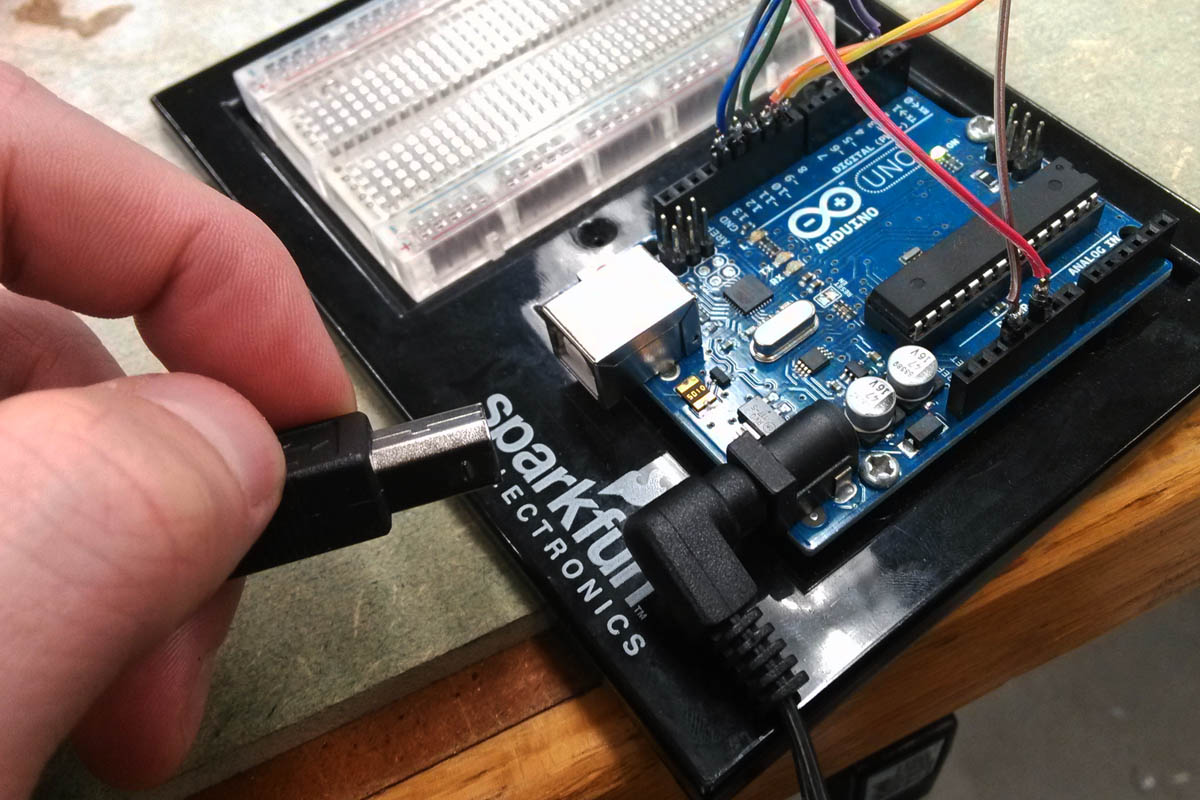
This week involved me needing to operate a Fabduino at 3.3V, as this was the requirement of the nRF24L01 transceiver modules (5V will damage the module). I didn't have a voltage regulator on the chip, but I figured I could use a 3.3V FTDI cable to program it. I plugged it in and started checking the voltages of pins to make sure I had the right ones going to the nRF module. I was surprised to see logic pins reading at 5V, and worried that this would damage the nRF module (turns out it won't).
I tried two other FTDI cables we had in the lab with the same results. Measuring the cable's VCC out read 3.3V, while the Tx and Rx read 5V. I did some research and found that this was typical of some kinds of FTDI cables. In this case it didn't really cause any problems (other than confusion), but it could potentially, so good to know.
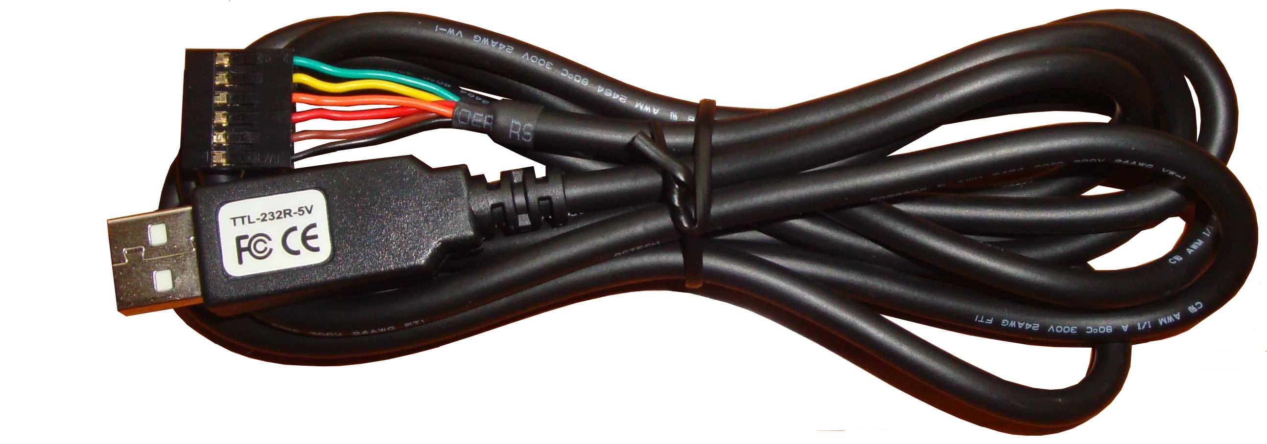
Digi-Key only offers two kinds of 6 female socket FTDI cables, the 5V and the 3.3V. The 5V runs both logic and VCC at 5V, and the 3.3V runs logic at 3.3V but VCC is still 5V.
TTL-232R-3V3
TTL-232R-5V
As far as I understood, that's all there was to it. But it turns out it's not so simple, as after much investigation and failed diagnoses, I discovered that my FTDI cable was 3.3V VCC but 5V logic. I had purchased my own FTDI cable from Amazon. The vendor was called "bluesky", and looking back for details, I could't find anything about the company, or even a part number of the product I ordered. So that's all pretty suspicious, and I remember banter in the class about "knock-off" or "fake" FTDIs, but what does that actually mean?
I was discussing this issue with NovySan in the lab, and when we couldn't find any conclusive answers, he asked Brian Mayton. I've pasted his answer below, as this should clear up any confusion.
"All FTDI cables originally put out 5V on the VCC line. The idea is that you might want to power your device from the VCC line, but it would be hard to include a regulator inside the cable end that could handle the full 500mA that USB can provide. So, the FTDI cable designers wired the VCC pin *directly* to the pin on the USB port, so you get on that pin whatever voltage the USB port is putting out.
Sparkfun and a few other vendors messed up that convention when they made their own FTDI adapter boards, and made the 3.3V I/O boards also have a 3.3V VCC pin. Some variants have a dedicated 3.3V regulator for this, and others use a 3.3V regulator that's built into the FTDI chip itself. The built-in regulator is not really intended to supply very much current to external circuitry (it's meant to just run the internal stuff in the FTDI chip itself). But you can pull 20-30mA off of it which is sometimes enough to run a microcontroller.
Since then, there are so many versions of FTDI cables and adapter boards (both authorized ones using real FTDI chips, and counterfeit knockoffs) that are wired in so many different ways that it's hard to tell what you have unless you are buying direct from FTDI or a very reputable vendor like Digikey (even places like Sparkfun sometimes source stuff from weird places).
The 5V on the VCC pin is really the best way to go, since then you get access to the full 2.5W from the USB port and can regulate it to whatever you want (and do so outside of the cable where you can actually dissipate a little bit of heat if you need to) but it's slightly less convenient because you have to include the regulator if you're making a 3.3V board.
In general, you just need to test the cables with a multimeter to see what you have."

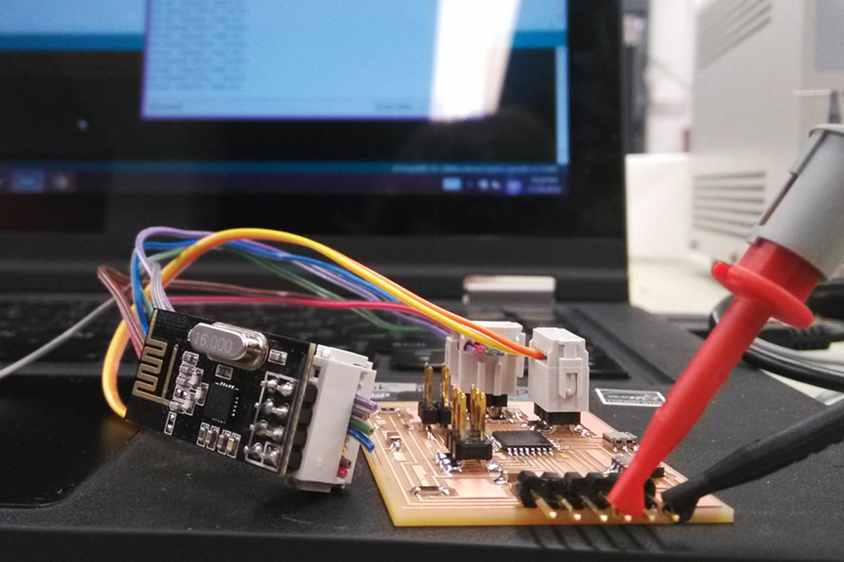
The above diagram outlines my abmitions for wireless control for my final project. I'd like to wirelessly control three nodes from from a RxTx board attached to the host computer. For this week's assignment I decided to focus on the carriage node, which would need to transmit accelerometer values and receive servo commands. I decided to use the nRF24L01 modules, recently commodified and new to the fab inventory this year.
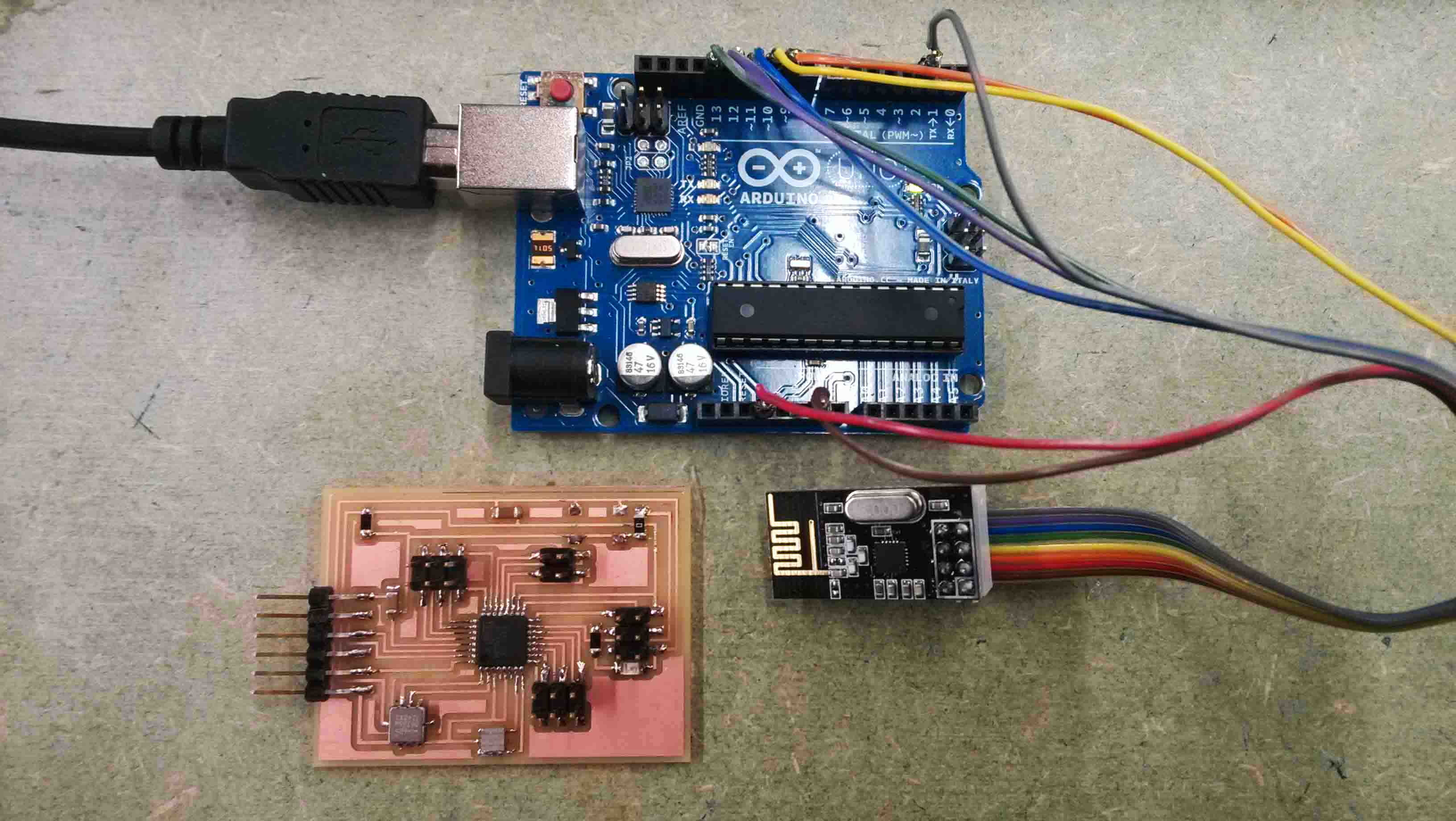
The ingredients for this week's assignment (hardware). The first step was to rebuild the Fabduino from two weeks ago. I never had it working totally right, so now was was a good chance to fix it. It now works fine, including the embedded accelerometer.
Burning the bootloader and programming the board. I used the Arduino IDE for programming, and used code from the tutorials at Maniacbug. This Wiki was also very helpful. However, I didn't connect the capacitor to the module as they suggested, but I probably will later.
I wired everything according to the tutorial, and uploaded the TxRx code. What's nice about the code is that it's one sketch that gets sent to all nodes. You can then toggle Transmit and Receive mode for each node through the COM port.
Unfortunately, since the Fabduino doesn't include USB serial, I had no way of monitoring it's serial. This was really a problem that made it difficult to work with the Fabduino, since I had no way of debugging or visualizing whether the transceiver was working or not. It would have also been helpful if there was an on-board LED on the module for feedback. I'm considering milling a mount board for the nRF modules to voltage regulate and to provide feedback via LEDs.
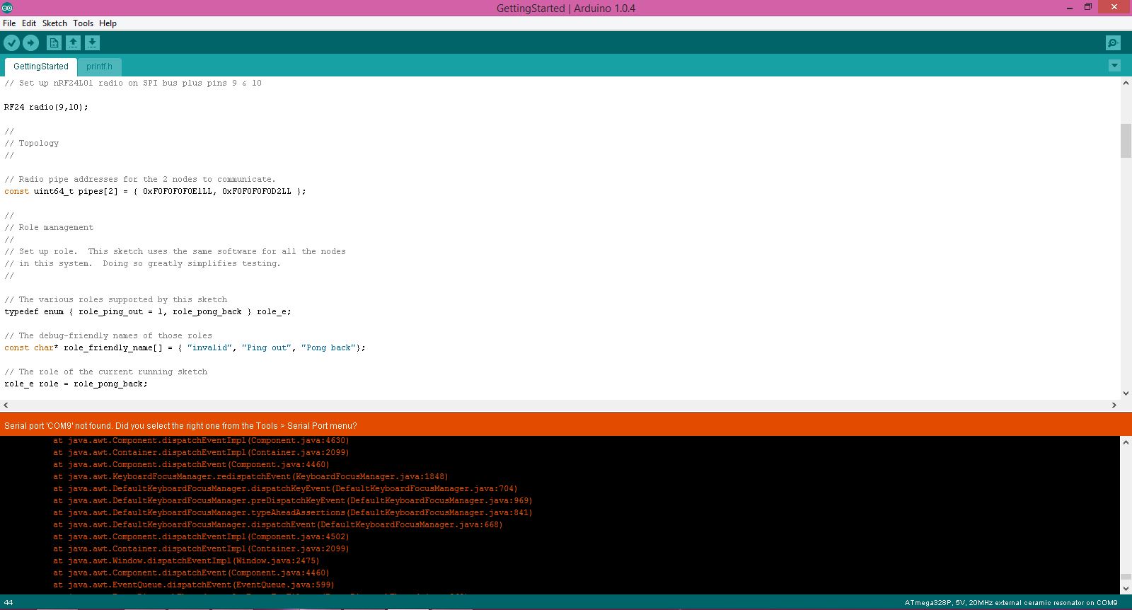
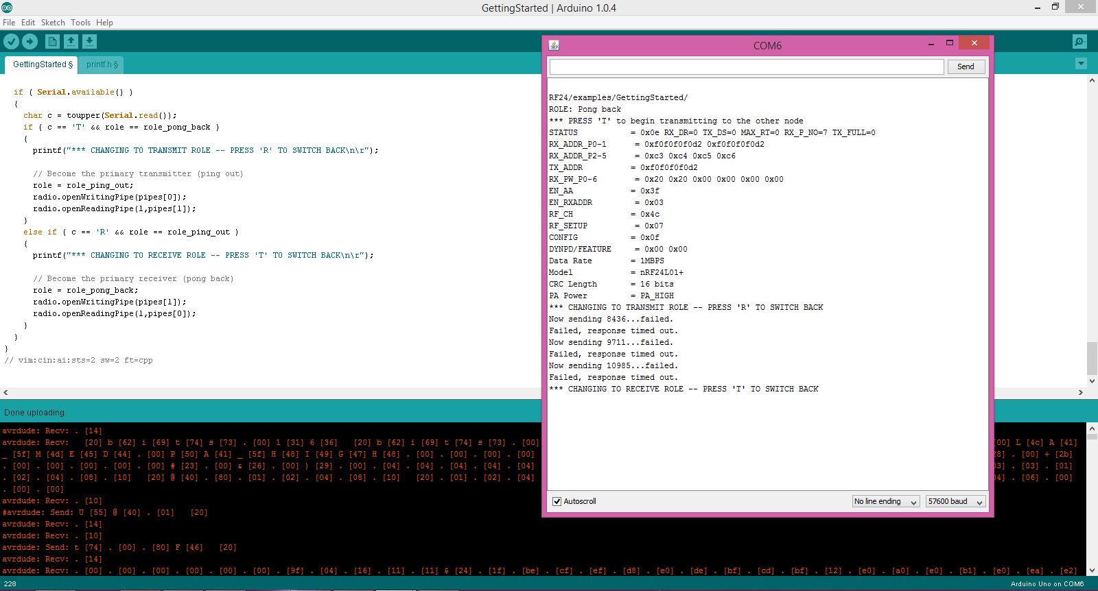
So, I first tried setting the Fabduino as a receiver and programming my UNO to be the trasmitter. Everything seemed like it should be working, but the UNO's serial port kept giving me the "Failed, response timed out." message. When I was programming the UNO, I opened the COM port and expected to see something like the following, as per the tutorials.
RF24/examples/GettingStarted/
ROLE: Pong back
STATUS = 0x0e RX_DR=0 TX_DS=0 MAX_RT=0 RX_P_NO=7 TX_FULL=0
RX_ADDR_P0-1 = 0xf0f0f0f0d2 0xf0f0f0f0e1
RX_ADDR_P2-5 = 0xc3 0xc4 0xc5 0xc6
TX_ADDR = 0xf0f0f0f0d2
RX_PW_P0-6 = 0x08 0x08 0x00 0x00 0x00 0x00
EN_AA = 0x3f
EN_RXADDR = 0x03
RF_CH = 0x4c
RF_SETUP = 0x07
CONFIG = 0x0f
DYNPD/FEATURE = 0x00 0x00
Data Rate = 1MBPS
Model = nRF24L01
CRC Length = 16 bits
PA Power = PA_HIGH
Instead, I saw all zeroes. Apparently from the tutorial, this basically can only mean that there is a bad connection somewhere. I refused to believe it at first, but finally realize I had two wires switched. I fixed that and then the COM port displayed the above information as was expected.
ROLE: Pong back
STATUS = 0x0e RX_DR=0 TX_DS=0 MAX_RT=0 RX_P_NO=7 TX_FULL=0
RX_ADDR_P0-1 = 0xf0f0f0f0d2 0xf0f0f0f0e1
RX_ADDR_P2-5 = 0xc3 0xc4 0xc5 0xc6
TX_ADDR = 0xf0f0f0f0d2
RX_PW_P0-6 = 0x08 0x08 0x00 0x00 0x00 0x00
EN_AA = 0x3f
EN_RXADDR = 0x03
RF_CH = 0x4c
RF_SETUP = 0x07
CONFIG = 0x0f
DYNPD/FEATURE = 0x00 0x00
Data Rate = 1MBPS
Model = nRF24L01
CRC Length = 16 bits
PA Power = PA_HIGH
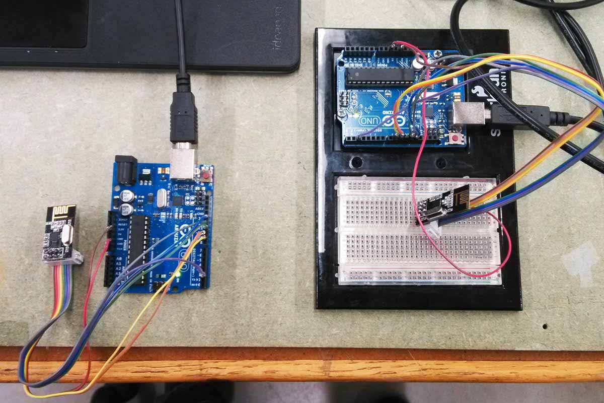
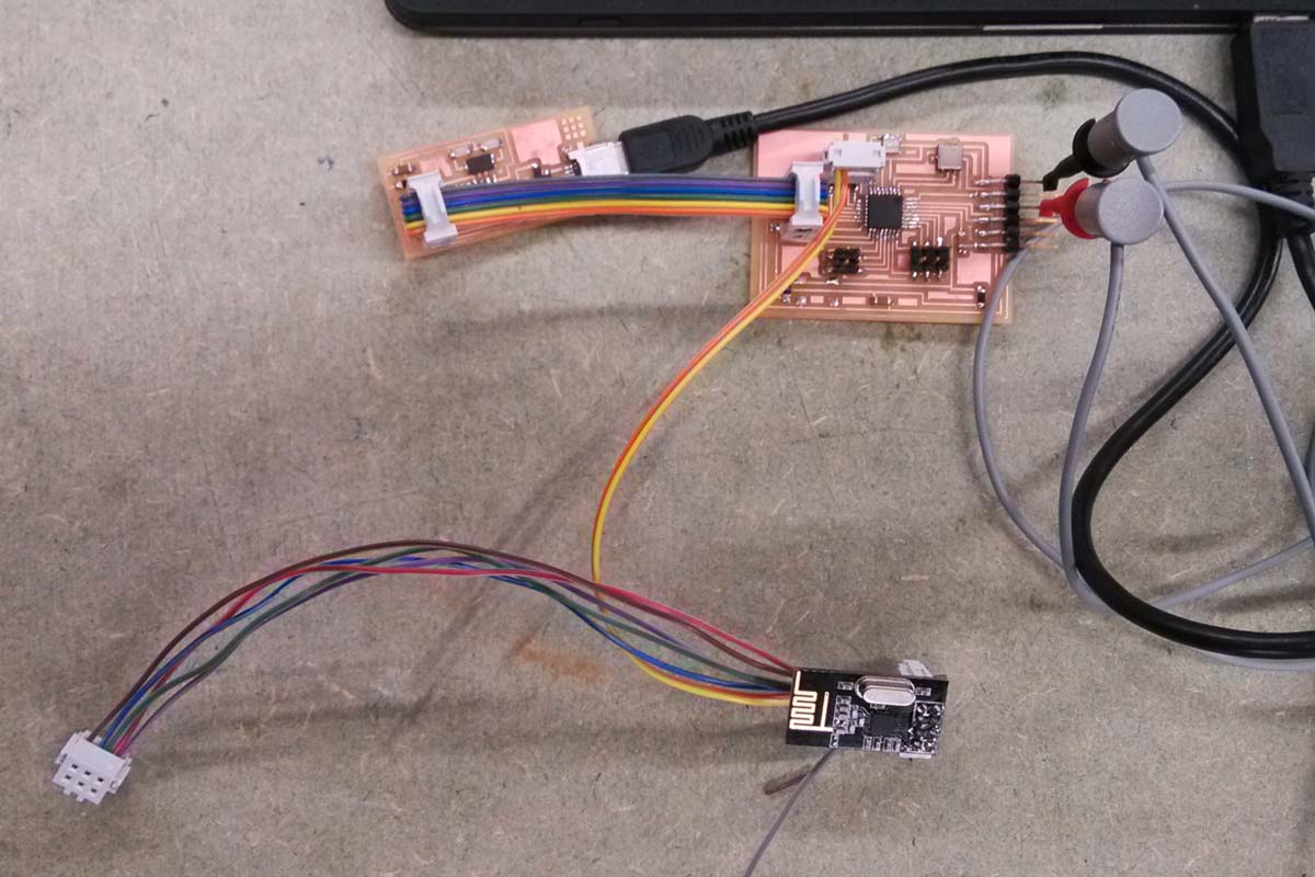
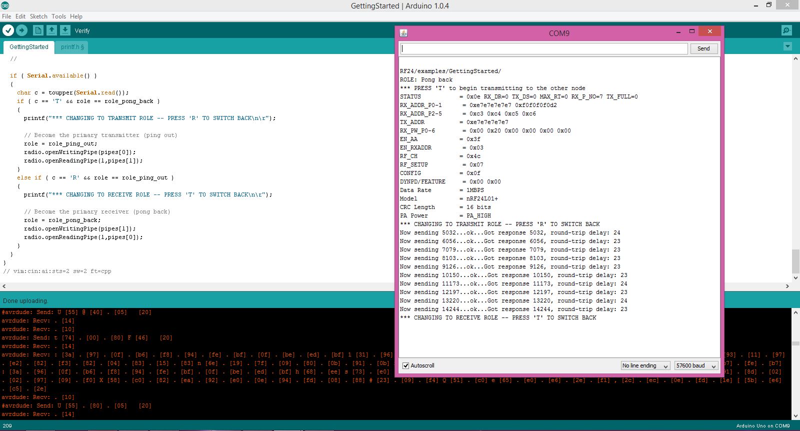
Unfortunately, I could only access this kind of information, which was essential for debugging, via the COM port, which the Fabduino didn't have. So, when my Fabduino couldn't successfully communicate with the UNO and I couldn't figure out why (I knew the UNO was working properly), I decided to try with two UNOs. Lucky for me, there was an extra UNO that had been left out on a table for weeks (...but really, who's is this? Can I borrow it? Thanks...)
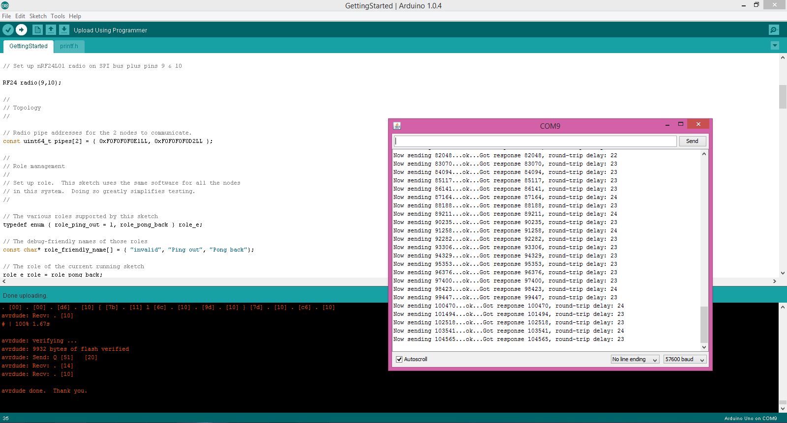
With two working UNOs and COM port feedback, I was able to get two devices talking to each other!
The weird thing was that this only worked when both UNOs were plugged into my USB ports simulataneously. When I unplugged one, and then plugged it back it, the other would fail to recognize it. It seemed as if once they lost synchronization, they weren't able to get it back again.
I kept trying having both powered simulataneously (but not both connected to my COM ports), tried setting them to different combinations of Transmit and Receive modes, but the only way the would communicate is if they were both programmed using the same computer at the same time.