Final Project: The Travelling Gnome
The plan
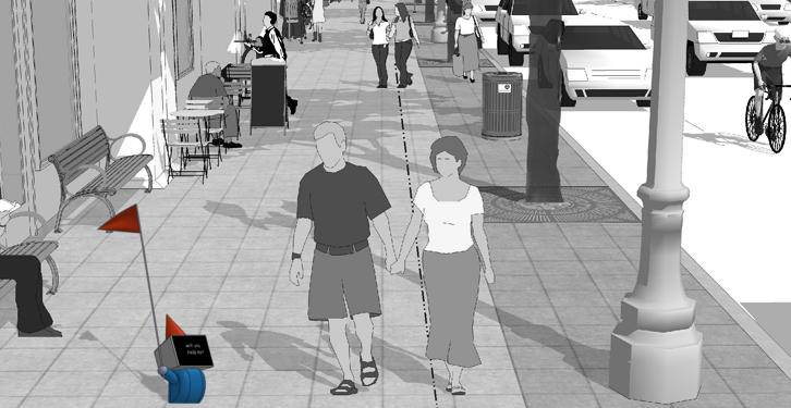
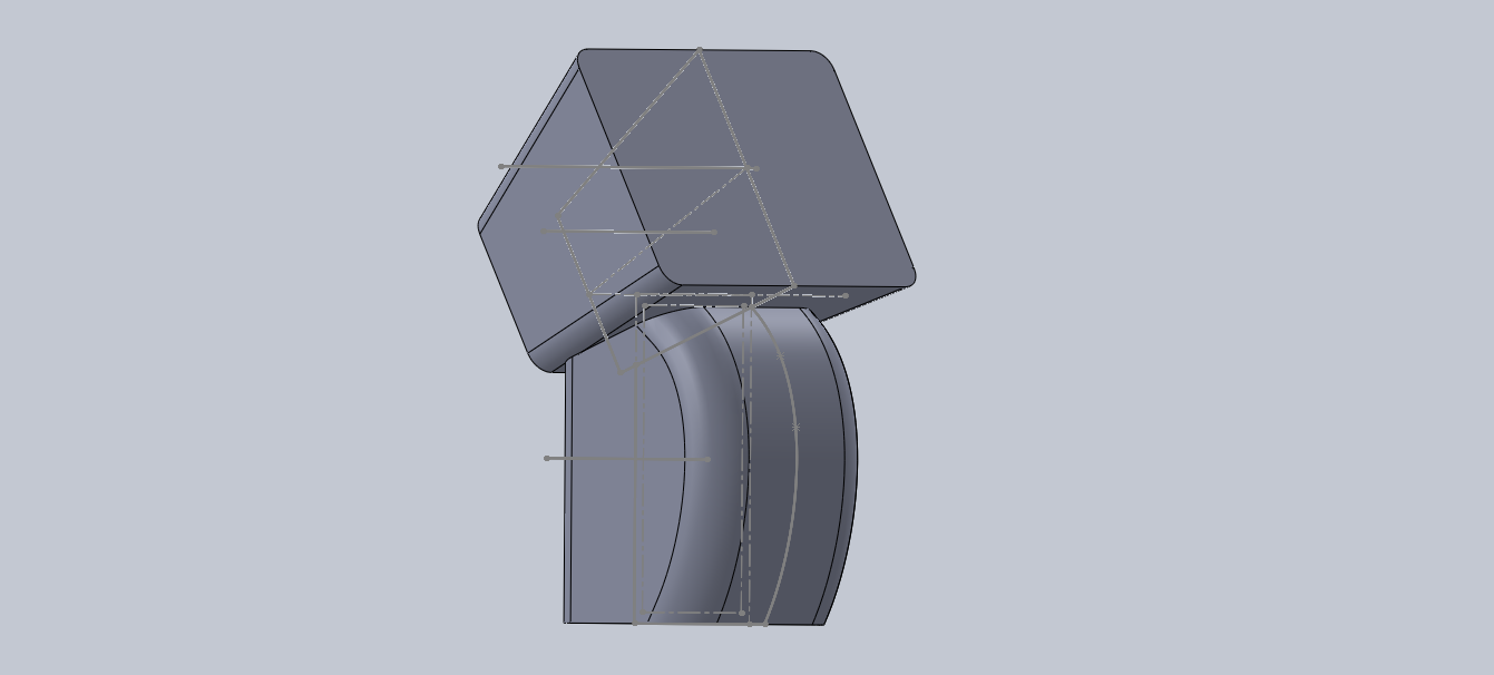
As you know, I wanted to build a gnome that would want to travel and rely on the kindness of strangers to get around. Here is the concept sketch from my proposal.
Building a gnome
I wasn't quite sure how to construct the body of the gnome. I looked at a couple of different options:
- cut paper / cardboard
- 3d print
- Molding and casting
3d print is most straightforward but not as neat as cut paper. Also very slow. I have a bit of experience with it. I love out of cardboard and paper. Pepakura gets rave reviews on this but assembly can be slow and probably not as structurally sound. Molding and Casting was Neil's recommendation. This will be quicker than 3d printing but it will require a 4 part mold and it will be difficult to repair the electronics.
V1 Paper test
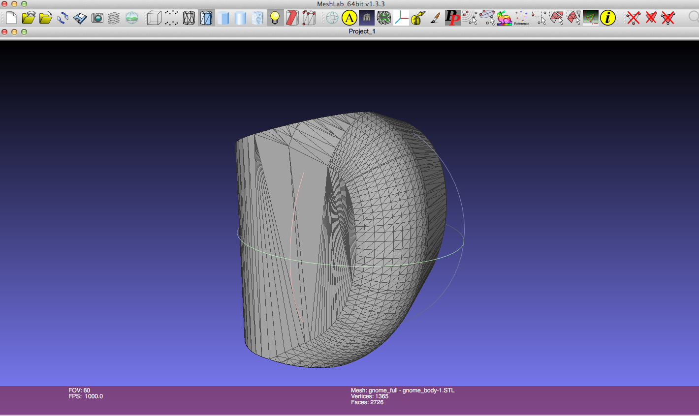
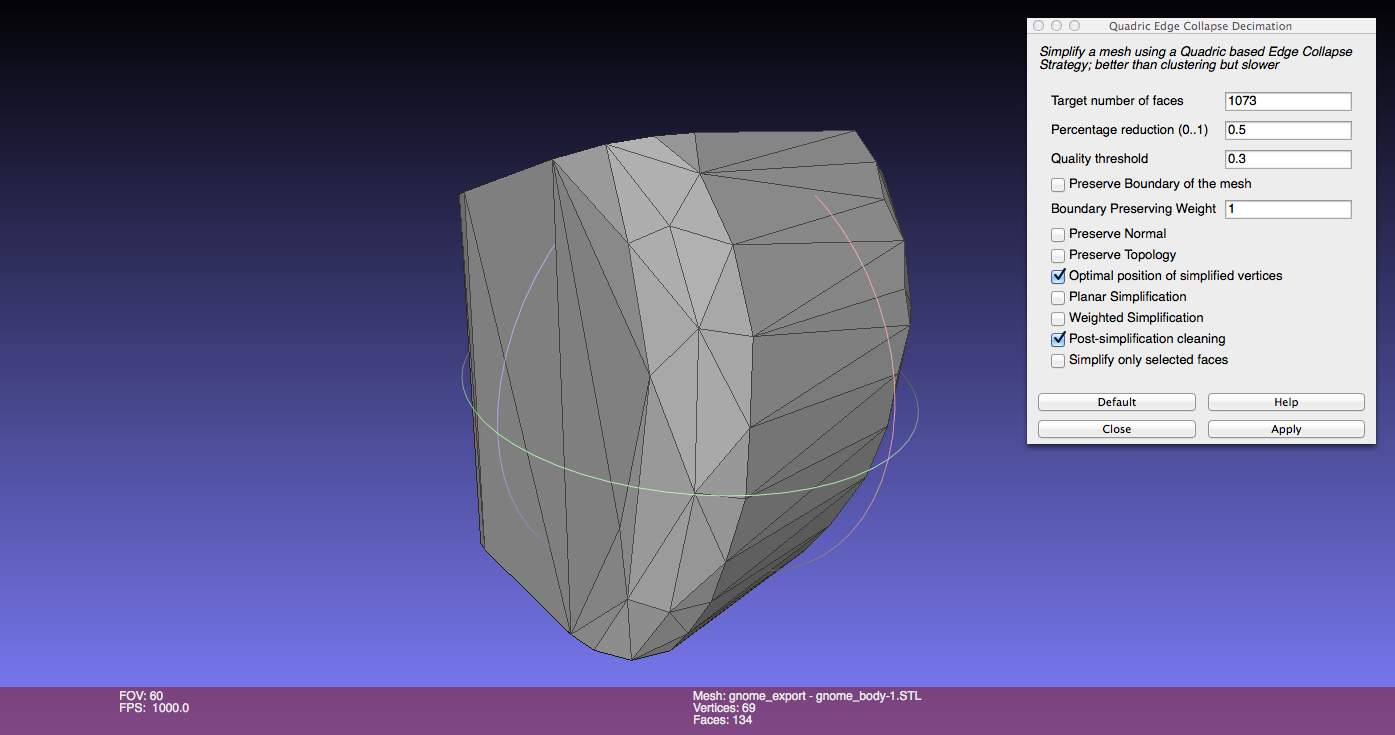
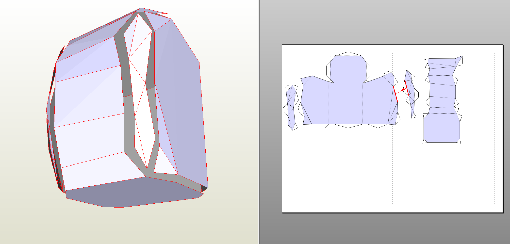
I decided to give paper folding a try. First I need to reduce the complexity of my design to reduce the number of faces. The initial output from solidworks had too way too many:
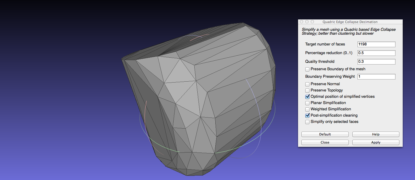
With meshlab, I could reduce the number of faces. Here is the process (applied iteratively):
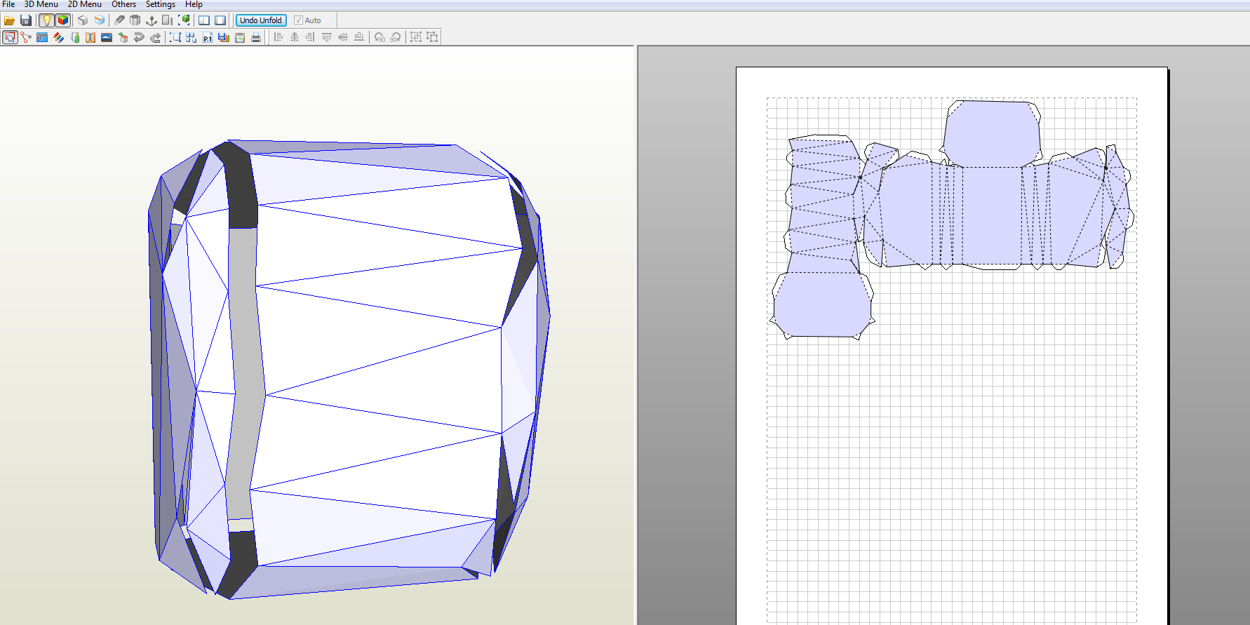
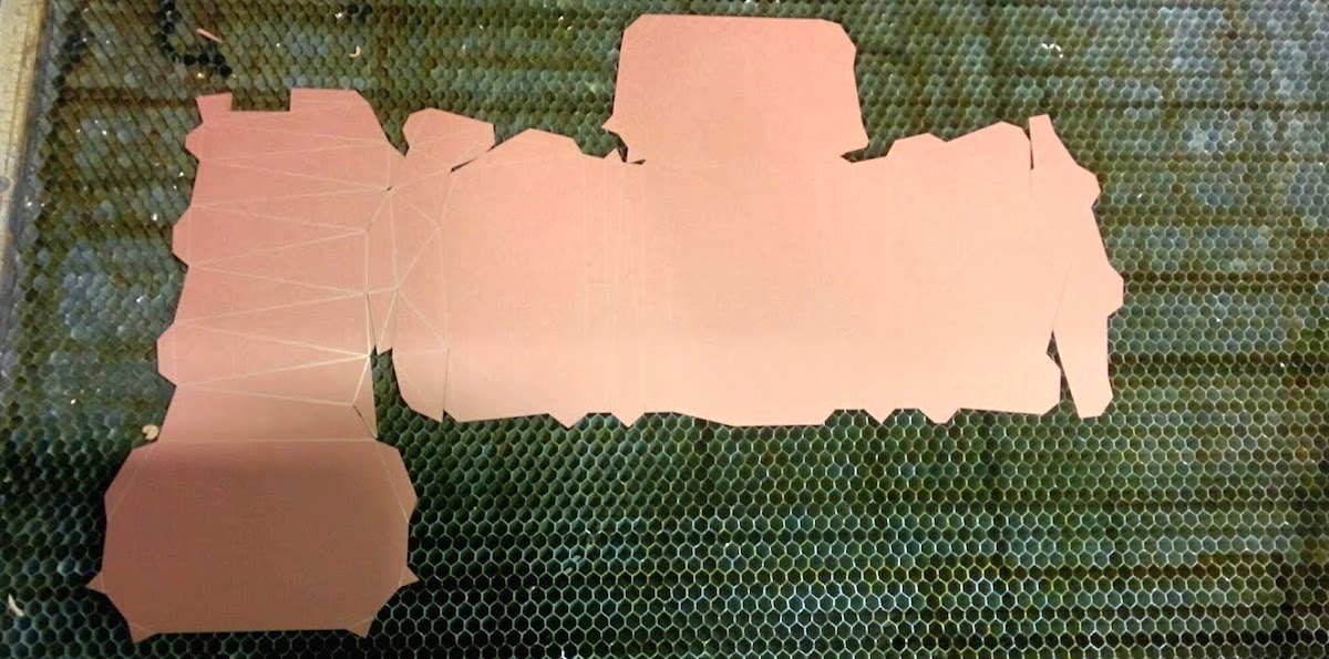
And the test output from Pepakura. Looks reasonable:
I exported these to corel draw and scaled it down to a manageable size.
Cutting using epilog
Alexis H had blazed the Pepakura trail and gave me these protips:
do color mapping on the dxf in the epilog printer driver menu
cut: 50% speed, 12 power, 500Hz fold lines (both mountain and valley): 53% speed, 2 power, 100Hz
art store is: Artist and Craftsman (http://www.artistcraftsman.com) on mass ave by central stop
Steps (for my own sake) - In print preferences set page size 36"x24" - select auto-focus
This completely failed to print. I found out that the documents primary color mode neds to be set to RGB and not CYMK. It is not sufficient to set the colors to RGB values. Failure mode is that the epilog will cut everything.
Incidently, the cut freq that Alexis suggested for cutting the card stock is great for scoring cardboard: Speed: 50%, Power: 12%, Freq: 474
Trying the following: grey (128/128/128) cut: Speed: 50%, Power: 12%, Freq: 500 blue (0/0/255) fold: Speed: 50%, Power: 7%, Freq 100 this worked maybe a little too well on the folds. Might be better to up the freq and lower the power.
This worked.
V2 Build
Now that I know that pepakura works, I redesigned the gnome in Solidworks using Carney's master sketch method. The previous cuts were done using the model I had made in week0 of the class. This time, I took into consideration the electronics (more on that below) and the battery that I intended to use.
4 applications of 50% decimation later...
btw, all the dimensions were huge. In solidworks, for save as DXF, choose options and make sure that size is in inches. Even then Pepakura scales the model to paper size or some aribitrary size which makes the output again enormous. Couldn't figure out how to rescale.
interesting. in pepakura, when I select manual unfold and put in the height (in mm) the scale factor comes out to be 25.4496 sounds like another case of inches/mm gone wrong.
Some pepakura tips. The output of pepakura isn't optimal. You can change where the cuts and folds go to make it easier to fold. After unfolding go over to the 2d Menu and click Edit Mode -> Join/Disjoin edges to modify the unfold.
Fixing the sacle in Pepakura and importing with units as mm in CorelDraw fixed the scaling issues. Well sort of.
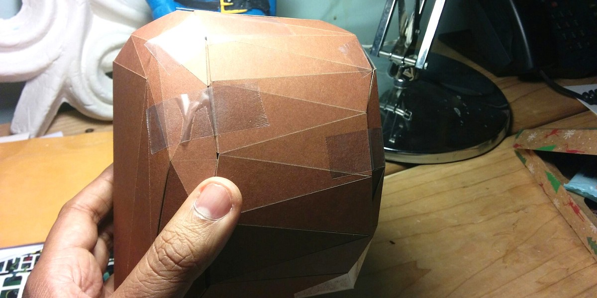
Here is another build:
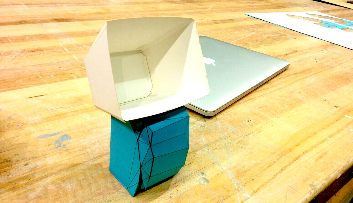
Little fella is quite fragile though. What it needs is a skeleton.
V3 build
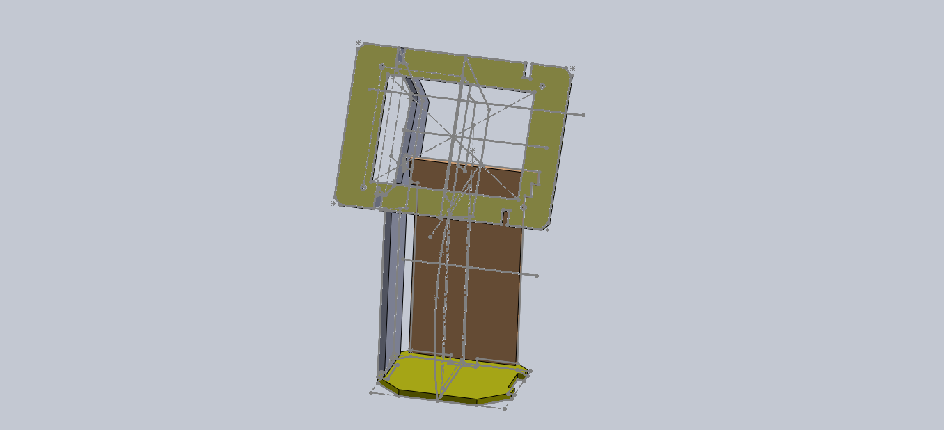
I designed a skeleton in solidworks. This is what I imagine a gnome's skeleton looks like:
I got hold of some 1/4" birchwood plywood from the scraps pile. I CNCed it using the desktop shopbot with 1/8" end mill. First in pathworks I added dog bone filets:
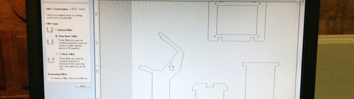
I ran into an issue where pathworks would refuse to put filets in. Turns out that sometimes vectors coming out of solidworks aren't joined. Edit > Join to fix.
Parameters for path planning:
- 1/8" flat end end mill
- cut depth 0.125"
- 20inch/min feed rate
- 15inch/min plunge rate
- stepover 20%
- rpm 12,000. (200 fps on desktop shopbot)
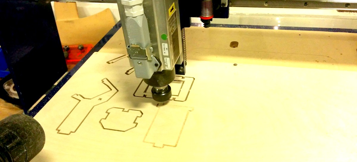
The parts were designed for press fitting and it worked nice and tight:

Two is one and one is none.
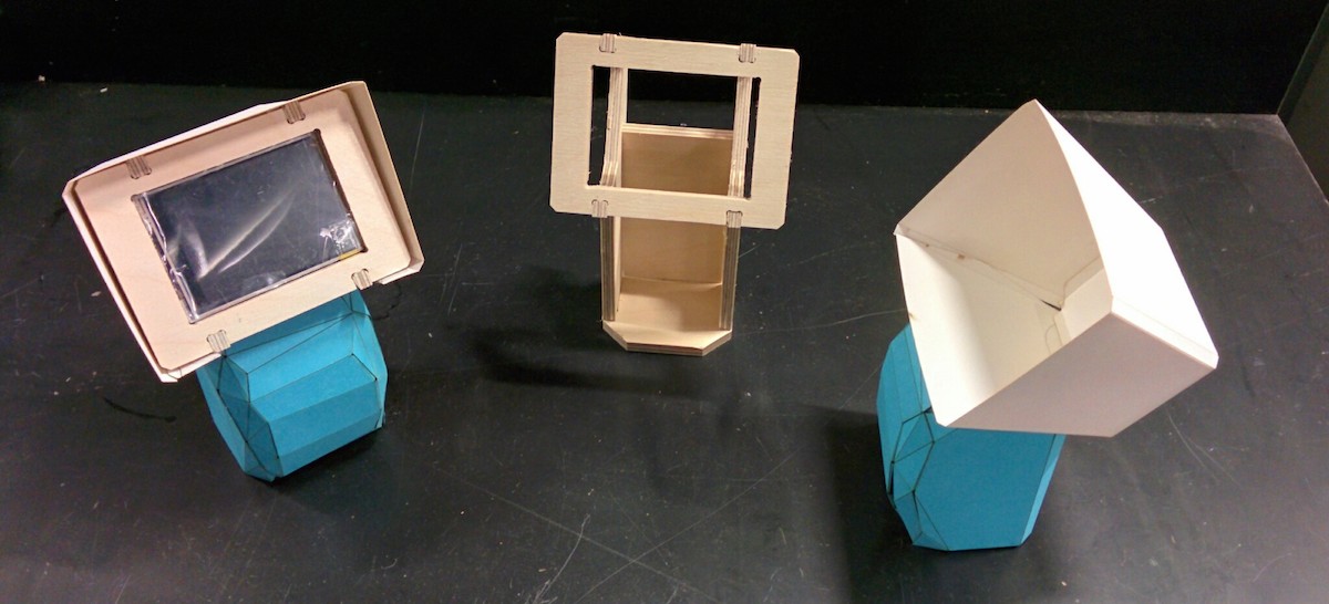
Here is the release candidate build with the skeleton. I designed the skeleton to give structure to the folding process and it helped a lot with paper folding.
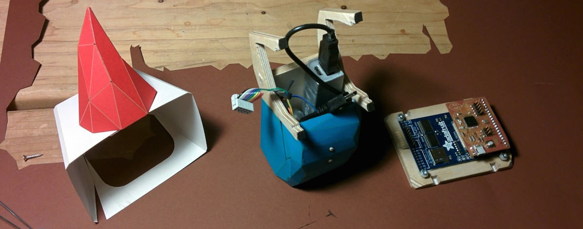
Electronics
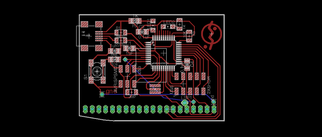
I designed it in eagle. The main components were to be:
- atmega32u4
- 2.8" lcd screen
- accelerometer
- esp8266
- buttons
- status leds
Unfortunately the first time I made the board I got the orientation of the display wrong.
Electronics v2
I remade the board and axed the wifi, deciding to move it to a daughter board clipped on to the 2x5 header.
Here it is stuffed and fried:
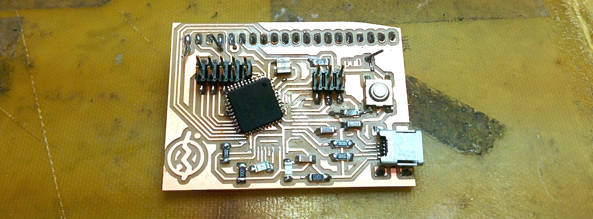
Fried because I hooked it up to the bench power supply and then turned it on only to realize that it was set to 10V. While trying to change the chip, I fried the board some more so I remade it and stuffed it again.
Inputs
The gnome needs to have inputs. Couple for the interaction and one to sense the ground. Initially I thought I was going to use cap sense for buttons and ground sense but if I could do actual buttons I didn't see why cap sense would make sense. So there are 3 buttons, one to sense ground and 2 for inputs.
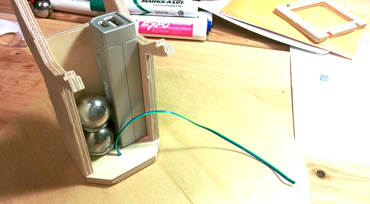
Power
For power I am using a USB battery pack. Duracell Powerbank 2600mAH. This should give the gnome ~24hours of power.
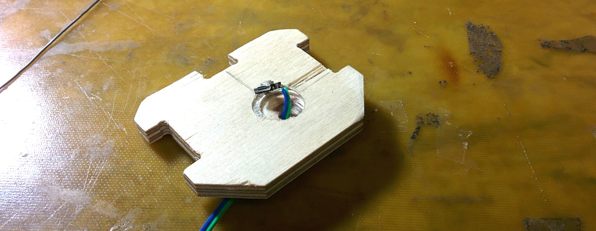
The weight of the battery wasn't enough to trigger the switch so I added in ball bearings to weight it down.
Final Build
Based on what I learned from the prototype assembling, I redid the body to be all in one piece.
The steps are: - design in solidworks - create a surfae with 0" offset for the faces I want - export as STL (in options make sure unit is set to inches) - use meshlab to decimate the surface down to low poly - pepakura to unfold - during unfolding choose manual, set conversition size to 25.45 - use 2d edit -> Join/Disjoin edges to get the output to be easy to fold - use 2d edit -> Adjust flaps to increase flap size where possible - Save As DXF to export - Import in Core Draw with units as mm (pep exports only in mm AFAICT)
The momentary switches are 0.170" in diameter. After the pepakura output, I edit the body in corel draw.
- grey (128/128/128) cut: Speed: 50%, Power: 12%, Freq: 600
- blue (0/0/255) fold: Speed: 50%, Power: 4%, Freq 90
Folding and sealing in the body. The battery and ball bearings are mounted using epoxy putty. Glue is book binding glue.
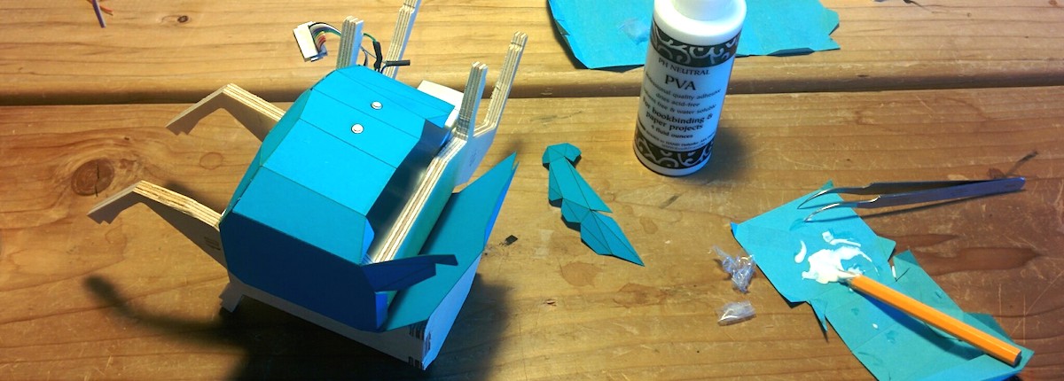
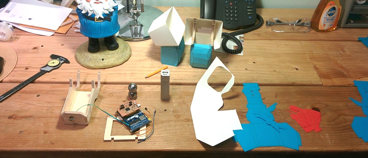
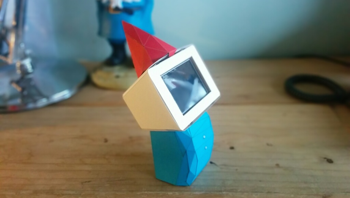
And now putting it together:
The finished assembly:
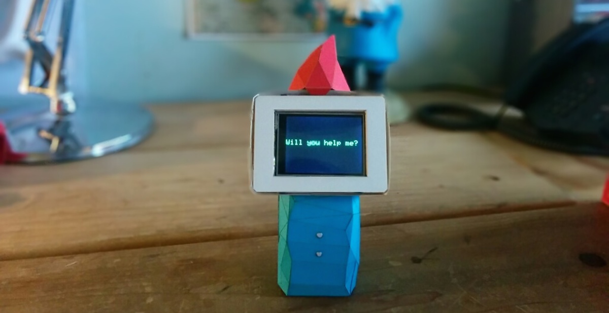
Code
I am designing the code to be a state machine. The states are waiting to get picked up, providing instruction, showing dissappointment, showing appreciation etc. Button presses, picking up, setting down and timeouts are transitions.
My buttons are connected like so:
Ground Sense - PD7 - D6
Top - PB5 - D9
Belly button - PB6 - D10
Arduino Command Line
As an aside, arduino > 1.5.0 has a command line interface:
- compile:
arduino --board arduino:avr:leonardo --verify sketch.ino - compile & upload:
arduino --board arduino:avr:leonardo --upload sketch.ino --port /dev/ttyACM? --verbose
This way I can use the libraries without having use the crappy IDE.
code snippet that shows how the transitions work:
// STATE: INSTRUCTION
//
// we are off the ground. give the person instruction on where to go
// and ask them if they are willing to take us there.
//
// transitions:
//   yes -> omw (on my way)
//   no -> rejected
//   timeout -> ???
//   down -> aborted

void enter_instruction() {
    state = INSTRUCTION;
    DEBUG("can you take me to paris?");
}

void loop_instruction() {
    if(buttons.yes_pressed()) {
        enter_omw();
    }

    if(buttons.no_pressed()) {
        enter_rejected();
    }

}
and in the main loop, we have this:
void loop() {
    switch (state) {
        case WAIT_FOR_PICKUP:
            loop_wait_for_pickup();
            break;
        case INSTRUCTION:
            loop_instruction();
            break;
        case OMW:
            loop_omw();
            break;
        ...
    }
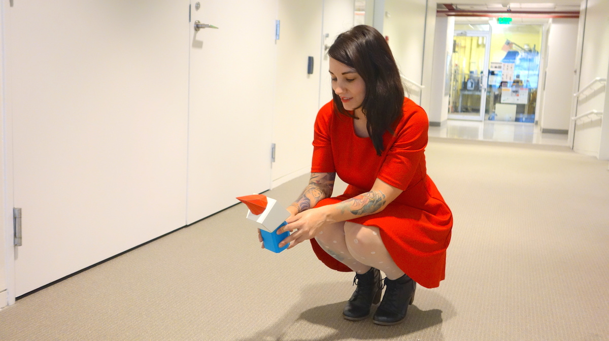
Out and about
Being a travelling gnome ain't easy
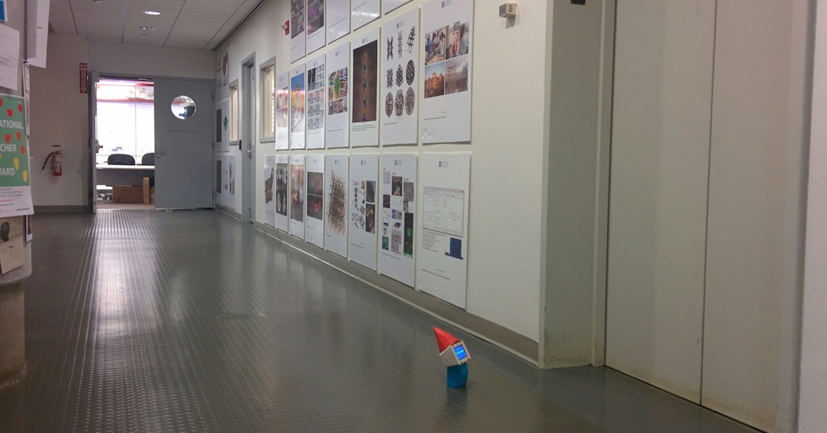
but sometimes you make friends along the way:
Bill of Materials
- Duracell power bank $22
- Adafruit 2.8" TFT $29
- AtMega32u4
- Folio Card Stock paper $3
- 1/4" birch (scrap wood)