|
|
MAS.863 How To Make (Almost) Anything
– Fall 2014 Richard Li Final Project – The Smart
Ukulele Week 14 The integration of topics covered in this class: The goal is to make a proof of concept high tech
stringed instrument such as the ukulele that can help you learn how to play
by using LEDs to display the chord shapes directly on the frets. In the
spirit of increasing the tech level of the traditional ukulele, this ukulele
combines virtually all the topics we covered in this class. Here are the
breakdowns of topics covered for instance: CAD – Solidworks CAD
of composites and casting molds Computer controlled cutting/machining – Waterjet for soundboard and headstock, Vinyl cutter for
prototyping Electronics Production – Vinyl cutting and
Roland MDX milling of boards, stuffing boards etc. 3D Printing – bridge/saddle, nut, molds for
casting fretboards Embedded programming – programming boards to
light up chord shapes on LEDs Composites – CFRP Body, Neck and Headstock Input / Output Devices – LED charlieplexing, LCD screen and future input of mic for VU meter capabilities Communications – capability on board to talk
through Bluetooth serial module (HC-05) Why
ukulele and carbon fiber you might ask? First, I don’t have one yet and been
meaning to want to pick one up and learn it for a while. Secondly, my
ambition is to build more complex structures out of carbon fiber and get
better at doing lay-ups especially with high performance materials to
eventually build something like a carbon acoustic guitar or bike frame. The
ukulele is nice in that it’s an ambitious starting point, but it won’t burn
through a ton of material in case the layup goes horribly wrong and doesn’t
have the mechanical intricacies such as truss rods in large guitars. As for the carbon argument, I’ve heard some amazing
sounds coming from carbon instruments before – such as when I went to
my good friend’s cello recital where she played with a carbon fiber cello.
Carbon fiber reinforced plastics (CFRP) are also incredibly durable yet have
high strength and stiffness to weight ratios – which is highly desired
for an ultraportable instrument such as the ukulele. Wood properties change
drastically with moisture and ambient conditions, whereas the carbon fiber
can be played casually on the humid Hawaiian beaches without a worry. What’s been done before: A group of three students at Tufts had started and
documented a fabrication of CFRP Ukulele, but did not end up finishing the
end product. In the end, their molding process is similar to what I had
planned, except they used a vacuum assisted resin infusion approach: http://www.tuftl.tufts.edu/musicengineering/research/CarbonFiberUke.pdf Also there is a company that sells LED embedded
guitars also as a learning tool (it’s cool to see others independently saw
the potential in this too!). No design yet on ukulele, and cheaper versions
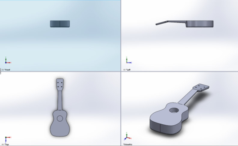
limited to only first 5 frets: Design, materials, components, and costs: As mentioned in my
composites page, this is modeled off of a Soprano ukulele, but designed to be made of three pieces with the body made of
one single composite piece, and the soundboard/neck cover as another separate
piece. Here is the solidworks part I modeled for
this body:
The idea
is that the fretboard would be a separate unit that
can be cast out of clear epoxy with an LED array embedded within it so that
light can shine through. The bridge and nut would be 3D printed out of harder
plastic like ABS. Strings, tuners would just be commercial off the shelf. One
additional neat feature I wanted to add was the capability to swap out fretboards quickly using magnets underneath the neck. I purposely also embedded disc
magnets within the fretboard conveniently shaped as
fret markers so that the board would be held down onto the neck. In terms of the cost, the
boards and circuits are only really a few dollars each. The tuners are about
8 dollars from amazon, and 3D printed material my amount to about 10 dollars.
The dominant cost is the carbon fiber, which I made with extra fabric lying around my laboratory. In general, you can buy the
carbon fiber fabric in bulk at >25ft at 10 dollars per food at 50” wide
(http://www.cstsales.com/carbon_fabric.html). In the end, the estimate cost
here using those numbers come out to < $~80 and factor in another ~$20 for
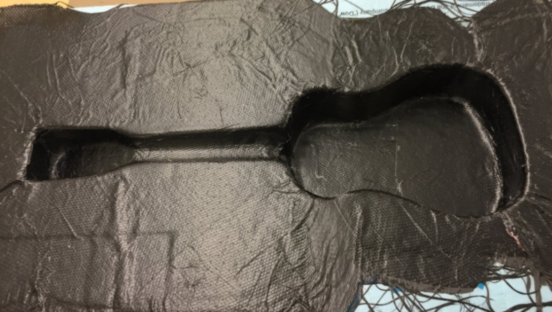
the total epoxy and hardener used up during the layup. Ukulele composite fabrication: Read more in my composites
page for more information on the mold design and layup tutorial: http://fab.cba.mit.edu/classes/863.14/people/richard_li/assign8.html But that was only the
beginning… Here are
all the post processing steps for fabricating the ukulele. First take apart
the vacuum bagging:
Here is a video depicting
the satisfaction you gain from peeling apart of the your peel ply to see what
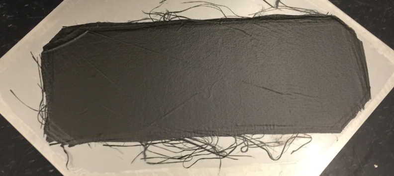
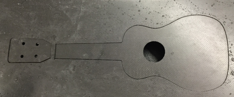
present awaited underneath: IMG 2437 from Rich Li on Vimeo. Then waterjet
the outline of the soundboard and headstock onto the flat plate. For the
soundboard waterjet file, in Solidworks,
I just opened my part, went to save as .dxf, and
then selected the front face as the object to be exported as dxf. One key thing for good mating is to purposely offset
the soundboard dimensions outwards so that when we go to mate it with the
body, excess material will be there from which we can then trim down and sand
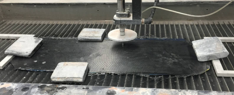
down flush. In the waterjet, be sure to use the
composite setting in OMAX:
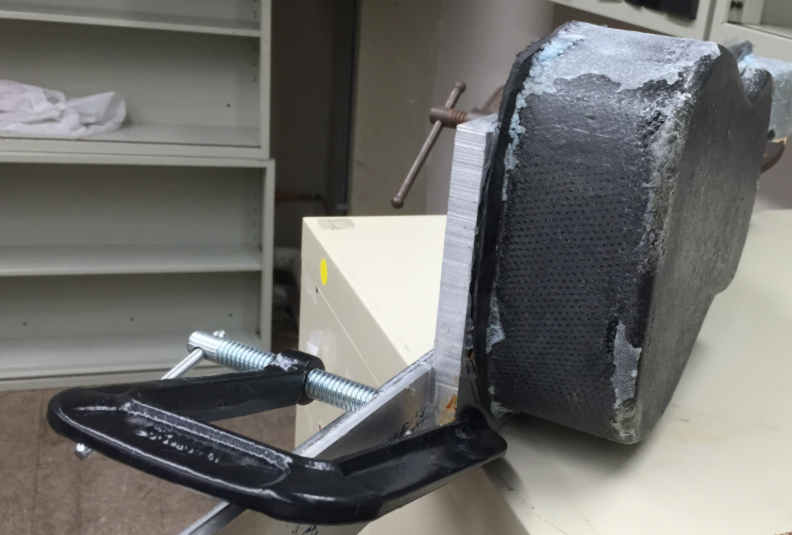
Next remove the body from
the mold and then hot-glue the lips to a vertical mount that can pass the
body through a band saw and cut it down to the right height. Note, I had
trouble removing mine, and ended up having to take apart my mold because I
didn’t seal the mold properly prior to putting on mold release or paste wax.
The result is that the sides of the body stuck very well to the foam. This
will require quite some patience and elbow grease to chip off eventually.
Also it’s crucial that the band saw you use has a hard abrasive coating on it
such as diamond grit band saw which is normally used
for cutting composites with ceramic fibers. Any other ones will ruin the
tooling quickly, and also result in very poor surface finish since it doesn’t
cut gradually with an abrasive pass. Be sure to feed it through slowly.
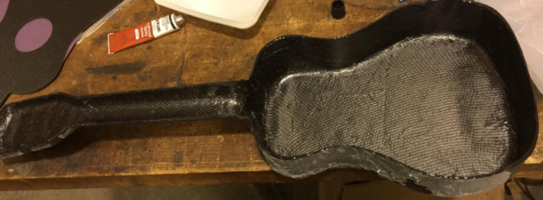
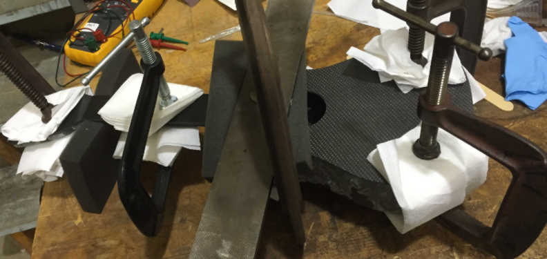
After it’s been cut down
to the right height:
You can use any two-part
epoxy and clamp down the soundboard to the body. Be sure to adhere (no pun
intended) to the cure times of the epoxy.
Ukulele Circuit Design This is probably where I
spent the most of my time this past week. I wanted to implement charlieplexing as that would
save a lot of pins. With 48 LED’s, I need 8 pins (up to 56 supported) in a 8X6 array for me. My straightforward charlieplex
diagram was like this at first:
However, the real issue is
that I have 12 frets and 4 strings. Thus the challenge was getting it to route
to a high aspect ratio rectangle (took at least a day to figure out)! Note
the interesting thing is that the schematic here below and above are
electrically identical. The only difference is that I installed a LOT of
jumpers (shows up as resistors on the bottom schematic) in order to get rows
to weave between each other.
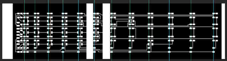
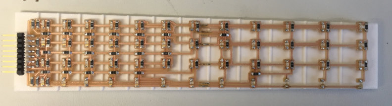
After some back and forth,
the neatest routing I can get is this. As you cans see, the 8 pin header are
all together on the left, and those spread out to each pin connected to a row
of 6 placed either in the left half or right half of the circuit board.
Additionally, the LED
driver board was designed as follows with capabilities for multiple outputs
such as for LCD display, pins for Bluetooth serial, and then pins (on the 2X2
header) for futureproofing when I come around to
hooking up a mic/opamp circuit which can turn my LED array into a VU meter. Given
the number of pins totally needed, I ended up needing to use an atmega 328p. This schematic does have one mistake, and
that is I hooked up two LED pins to ADC 6 and ADC 7 which
will not do outputs. That’s a rookie mistake, and for the purposes of moving
forward I just soldered on jumper cables, but have not updated this schematic
below.
The board
layout for this circuit looks likes this, again heading the above warning on
pins ADC 6 and 7. I ended up using PB1 and ADC5 instead for two of the LED
pin outs instead.
The other issue is that
free Eagle has a size limit. Thus I had to use Photoshop and split the LED
board into small strips and stretch out the sections to match the coordinates
of the frets. Using the guide tool was super helpful to make sure I had the
right fret spacings.
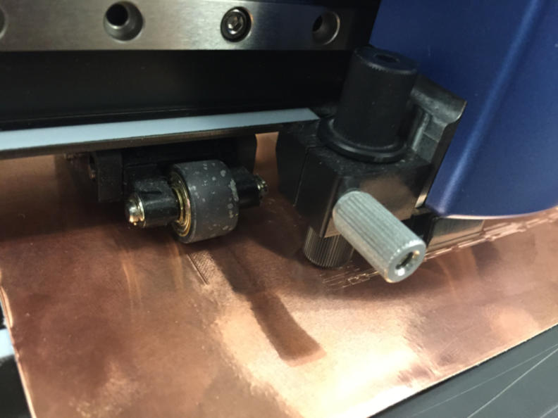
Circuit Fabrication Due to the desire to have
a transparent fretboard, I originally envisioned
vinyl cutting copper tape and adhering that to a fretboard
and then stuffing it. Toolpaths were generated once again using the fab module by Neil Gershenfeld, more information of which can be found from
my previous weeks’ documentation. However, it quickly became clear
that the vinyl cutter was not suited for this operation as the result would
either drag apart my traces
or just not cut hard enough. It’s a difficult balance
to play between force applied and the trace resolution you can get without
tearing it apart.
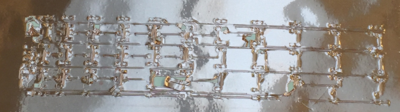
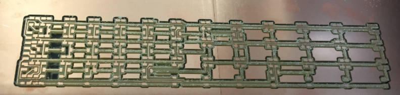
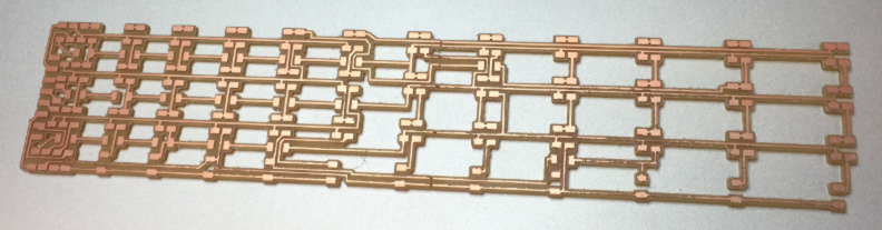
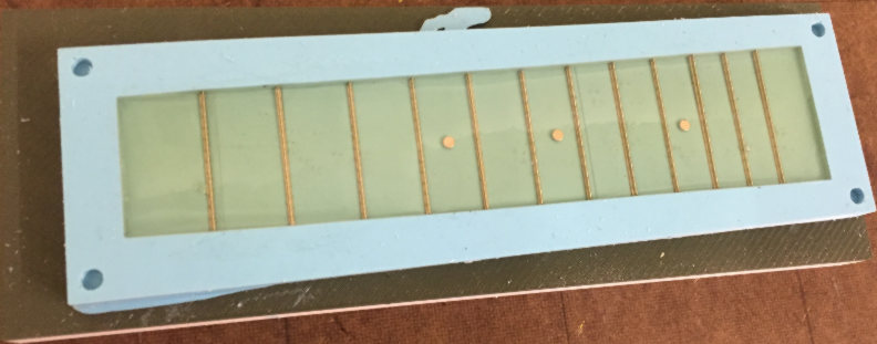
After an all-nighter in
the shop a winner became clear. It seems another way I can get transparency
while still using a method that can do high resolution trace cutouts (i.e.,
the Roland MDX) is to cut away any interior geometry all the way through the
thickness of the board. The shop didn’t have long enough copper boards so I
ended up putting two next to each other prior to milling on the MDX 20.
It was a great success:
the traces came out very cleanly, and the in between sections were fully cut
all the way. The way I achieved this using the fab module is to import my
trace file, select the milling method to be 1/32” outline cut (which cuts
through the full board thickness), and then adjusting the tool diameter to be
1/16” so it would go in to cutting the island traces out from the rest of the
board but would still mill out bigger contiguous in between regions.
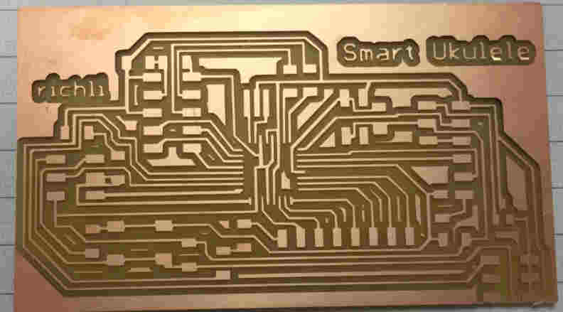
The milling of the driver board
proceeded without a hitch after quite a bit of practice over the past weeks.
Programming
- CharliePlexing The order of operations
for charlieplexing consists of three steps: 1. Set all
8 pins to high impedance, 2. Set the pin connected to LED anode you want to
light up to high, and 3 set the pin connected to the LED cathode you want to
light up to LOW and have that be in a loop until you want another LED state.
It’s a lot of lines of code over time to set this up. Good thing Arduino has a Charlieplex
library that works with these three steps. Below is the Charlieplexing code I wrote and modified from an online Charlieplex arduino library.
Several things should be noted. First is the assignment of 2D arrays called highpin and lowpin, which maps
the anode and cathode pins respectively to the real life coordinate of a
specific LED. Say for instance, I want to turn on the LED for first fret at
first string, the index of [1][1] would be used for highpin
and lowpin to give me the anode and cathode pins
for that LED to actually turn that on. I found a pattern in the mapping and
wrote that in as a for loop in the beginning of the
code. Next, to light multiple
lights with a chord, charlieplexing actually turns
only one LED in the chord on at a time but cycles through it so quickly that
through persistence of vision, makes it seem like they’re all on at the same
time. Thus you’ll see that for the chords programmed in, I have a while loop
just cycling through the LEDs that define the code shape. If I want to have a
chord for a certain time interval and then move onto another chord, the key
trick I used here is the “millis()” function which gives me a starting time stamp for when
I enter the chord loop, and then current time stamp through each loop
iteration, and have it exit the loop once the time interval for that chord is
up so it can move onto another chord’s looping through its own LED’s. That
pretty much the core of how this code works: //#include <Arduino.h> #include <SoftwareSerial.h> SoftwareSerial mySerial(6,4); #include <Charlieplex.h> #define NUMBER_OF_PINS 8 #include <LiquidCrystal.h> LiquidCrystal lcd(4, 3, 5, 6, 7, 8); //define pins in the order you want to adress them byte pins[] = {A3, A1, A5, 9, A4, A2, A0, 10}; int highpin[13][5]; // 2D array of the anode pins
corresponding to the index in the [][] int lowpin[13][5]; // 2D array of the cathode pins
corresponding to the index in the [][] int s = 0; int f = 0; //initialize object Charlieplex charlieplex = Charlieplex(pins,NUMBER_OF_PINS); boolean singleOn =
false; int starttime
= millis(); int endtime = starttime; void setup(){ // initialize serial communication at 11500 bits per second: mySerial.begin(11500); lcd.begin(16,1); // Start LCD screen output //Map
the indices for highpin and low pin to the actual
pin numbers. for(int row=1;row<=8;row++){ int column = 1; // for the column address for (int c=1; c<=6;c++){ if (column == row){
column++; } if (row <=4){
s = row;
// if row<= 4
f = 6-c+1; // } if (row >4){
s = row-4; // if row >= 4
f = 12-c+1; // } highpin[f][s] = column-1; lowpin[f][s] = row-1; column++; //c++; }
} } /* void Cchord(int dur){
//This is a function that would spit out a C chord on your fretboard
starttime = millis();
endtime = cstart;
while ((endtime-starttime)
<= dur) {// do this loop for up to 3000 mS
charlieplex.clear();
charliePin ledtemp5
= {highpin[1][2], lowpin[1][2]};
charlieplex.charlieWrite(ledtemp5,HIGH);
charlieplex.clear();
charliePin ledtemp6
= {highpin[2][1], lowpin[2][1]};
charlieplex.charlieWrite(ledtemp6,HIGH);
endtime = millis(); } } */ void loop(){ if (singleOn){ charlieplex.clear(); } //Cchord(5000); //charlieplex.clear(); //delay(1000); // Light
up all frets int gstart
= millis(); int gend
= gstart; while ((gend-gstart) <= 5000)
{// do this loop for up to 5000 mS
int row = 1; // for the row address = for printing every light
for(int
row=1;row<=8;row++){ //int c = 1; //
counter for where along the row it's printing - want it to print across each
which is 6 int column = 1; // for the column address for (int c=1; c<=6;c++){ if (column == row){
column++; } charlieplex.clear(); charliePin ledtemp
= {column-1, row-1}; charlieplex.charlieWrite(ledtemp,HIGH); column++; }
} gend = millis(); } charlieplex.clear(); delay(2000); // C
Chord lcd.clear(); lcd.setCursor(0,0); lcd.print("C Chord"); int cstart
= millis(); int cend
= cstart; while ((cend-cstart) <= 3000)
{// do this loop for up to 3000 mS charlieplex.clear(); charliePin ledtemp
= {highpin[3][4], lowpin[3][4]}; charlieplex.charlieWrite(ledtemp,HIGH); cend = millis(); } // G
Chord lcd.clear(); lcd.setCursor(0,0); lcd.print("G Chord"); gstart = millis(); gend = gstart; while ((gend-gstart) <= 3000)
{// do this loop for up to 3000 mS charlieplex.clear(); charliePin ledtemp1 = {highpin[2][4], lowpin[2][4]}; charlieplex.charlieWrite(ledtemp1,HIGH); charlieplex.clear(); charliePin ledtemp2 = {highpin[2][2], lowpin[2][2]}; charlieplex.charlieWrite(ledtemp2,HIGH); charlieplex.clear(); charliePin ledtemp3 = {highpin[3][3], lowpin[3][3]}; charlieplex.charlieWrite(ledtemp3,HIGH); gend = millis(); } // F Chord lcd.clear(); lcd.setCursor(0,0); lcd.print("F Chord"); cstart = millis(); cend = cstart; while ((cend-cstart) <= 3000)
{// do this loop for up to 3000 mS charlieplex.clear(); charliePin ledtemp5 = {highpin[1][2], lowpin[1][2]}; charlieplex.charlieWrite(ledtemp5,HIGH); charlieplex.clear(); charliePin ledtemp6 = {highpin[2][1], lowpin[2][1]}; charlieplex.charlieWrite(ledtemp6,HIGH); cend = millis(); } } Here is an example of the
G chord shape lit up!
Here is a video of the LED
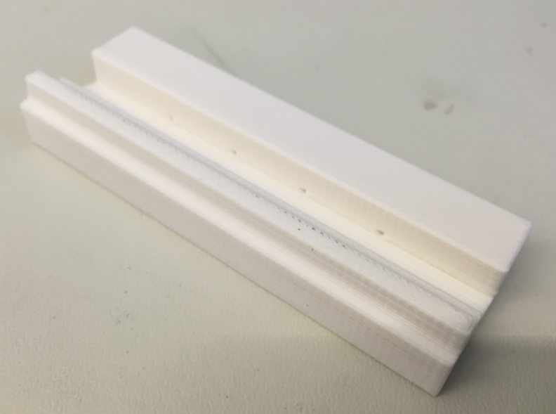
board first working on its own: IMG 2851 from Rich Li on Vimeo. Molding/Casting the Fretboard: With the electronics up
and running, it was time to make the fretboard. Fretboard postive molds were
designed in solidworks and 3D printed on the
Dimension. I then cast oomoo into these 3D printed
molds to get the negative molds, within which I can case
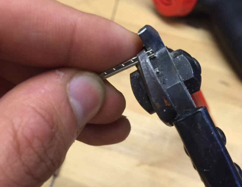
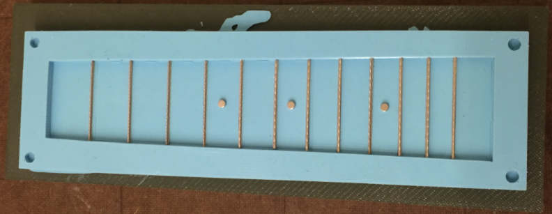
my clear epoxy to get my fretboard. To embed
components within the epoxy, I first cut low/narrow fretwire
(which can be ordered from a guitar parts supply store such as stewart macdonald online).
I then
placed the frets individually down into the grooves of the negative mold, as
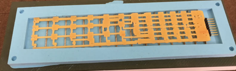
well as the magnets used as the fretmarkers and the attachment to the neck. Next, I can place my
electronic board on tome, and then cover the mold with the top half before
pouring epoxy in through the top. As this was my first trial run, I actually
didn’t throw in my LED board into the mold this time just in case the casting
didn’t work out.
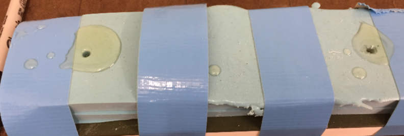
It was a good thing I
didn’t. One thing I notice was that the holes I for pouring were too small,
and I found a lot of air entrapment as I added epoxy:
As a result, I took off
the top mold, and just did a simple open one part mold instead, which seemed
to work very well in distributing the epoxy.
This
process seems to work, and once I can confirm the playability of this
fretboard, I’ll embed my LED board into the epoxy with the next casting I do. 3D Printing as a tool for mold making and
prototyping Being able to 3D print the
fretboard first was incredibly helpful to verify
the position of my LED fret lights. A big thanks to Athina
P and Anna Young for their help in printing on the dimension printer on the IDC which worked seamlessly.
The saddle and nut of the
ukulele was 3D printed successfully as well.
And of course the casting
positive molds I mentioned earlier.
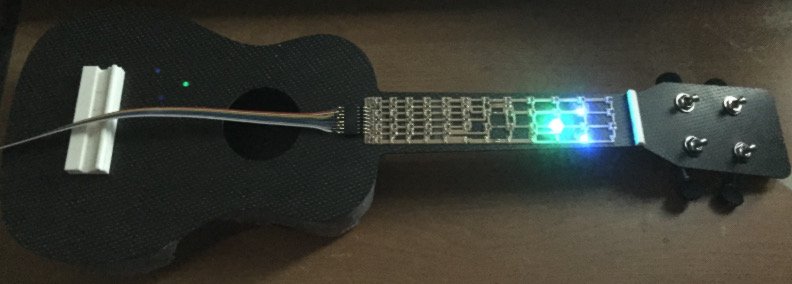
Test run: With the board mounted to the
neck of the ukulele, the final effect that can be achieved is shown in this
video: IMG 2878 from Rich Li on Vimeo. In the meantime, the board
is outputting the chord names to the LCD screen so a person playing this can
not only see the chord shape on the fretboard, but
also learn the names through the screen.
Questions, insights, and implications: Lots of challenges and
uncertainties appeared in this project that covered virtually the full range
of units in HTMAA. In just the composites part alone,
there was uncertainty in using foam as the mold. Would the blue foam be too
compliant and not be able to hold its shape during vacuum layup? Would the
piece stick to the mold given the lack of a draft angle? Turns out the foam
did a good job at holding shape, but not so much at allowing an easy release.
The key issue is not the draft angle as much as the surface seal of the foam.
After milling out my foam mold, I noticed the sides were extremely fuzzy. I
placed only one thin coat of entropy 100 epoxy onto the
surface, but not enough of that stuck on. The application of paste wax
was not enough to fill in the pores and completely seal the surface, thus
epoxy was able to penetrate into the foam when I did my layup, and cause
anchoring of my part. Even after removal of my part, it’s still hard to chip
away at the pieces of epoxied foam from the surface, indicating an
anchoring/adhesive effect rather than a mold geometry effect. In the electronics design,
there were questions about how I can stretch out a board given my limitations
on size for developing it eagle. I found a workaround which
is to squeeze everything under the limits, generate the trace .png file and then use photoshop
or some image editing software to stretch it out to the right spacing. In the electronics
fabrication, there were questions about vinyl cutting the traces that small.
Indeed, that process wasn’t successful, but using the roland
MDx20 router, and then milling through the whole board to get a transparent
effect off the traces worked very well. The next steps will be
embedding the LED into the fretboard now that the
electronics and epoxy casting were shown to work. The next iteration will
have to decide on the best wiring and positioning for playability of the
ukulele so electronic wires don’t interfere. With the infrastructure
built, there are lots of fun things that can be built on the software and
hardware end. I’d like to code something that would allow the importing of
tablature found online, parsing it into LED light coordinates and turning it
on so I can start learning songs. Bluetooth serial can also be connected to
the driver board pins to allow wireless serial communication to the computer
or phone sending the parsed LED light coordinates. Of course, an enclosure
will be designed to have a smaller footprint, and easy mounting to the
ukulele while being powered by a 9V battery (via bottom right pins of the
board and voltage regulator). Definitely lots of fun things to try out in
version 2.0! |
|
|
|
|
|
|
|
|
|
|
|
|
|
|
|
|
|
|
|
|