Cube from a kit
I bought a diy LED cube kit a while back, and made it this past week in preparation of this project. It helped me get used to using a rig to hold the LEDs while soldering, and connecting layers together to make a cube. The actual circuitry part was already done, I just needed to solder componenets into place. In this cube, all cathodes are connected in each column, and all anodes are connected in each row. They're controlled using transistors, which amplify current and are used as switches. After builing this, I removed the cube from the base and directly connected the columns and rows to pins in my arduino. I then was able to turn on speciic LEDs with just a resistor put inbetween the cathode and ground. Unfortunately, I forgot to take pictures/videos of this. :(
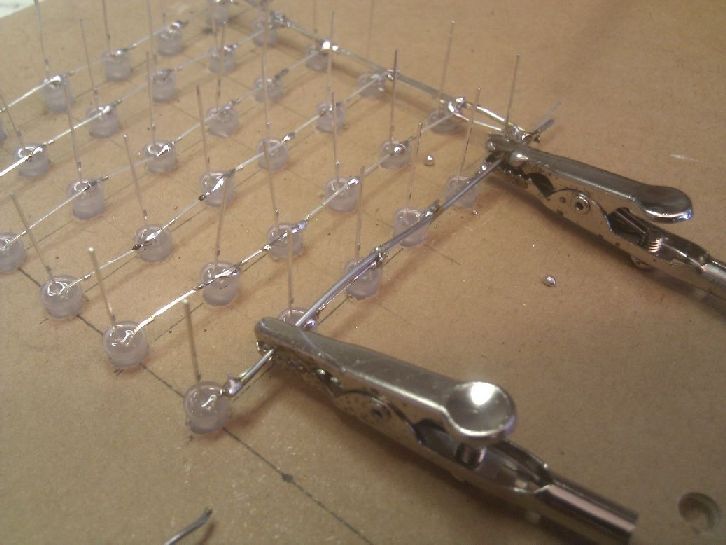
Starting 6x6x6
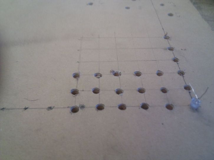
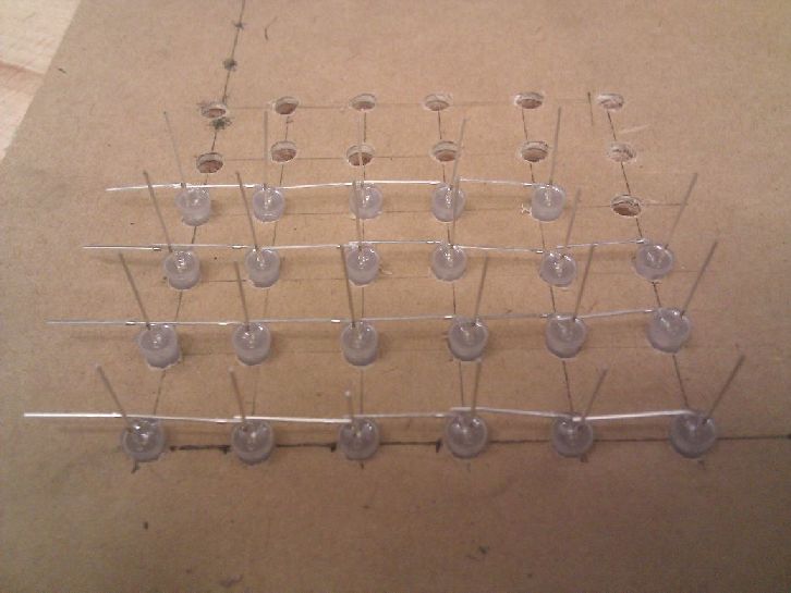
I first made a rig to hold the LEDs while I was soldering them. I tried different drill sizes, until I found one where the LED would fit snugly. Then I cut out 36 holes in a square, making it so that there would be a ~1mm overlap between anodes in a layer. In my design, the cathodes (negative) of each LED are connected in a layer (just used pliers to bend them 90 degrees), and the cathodes (positive) are connected in each column (used pliers to bend them toward the column and make soldering easier).
Testing LEDs and connections
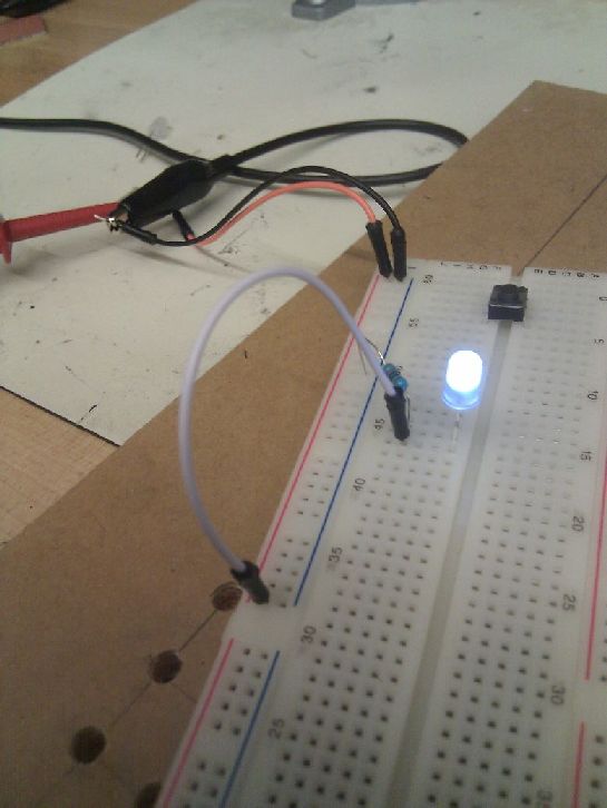
I was a bit paranoid that some LEDs might not work, so I tested each one out before adding it to the cube. I found 2 LEDs that wouldn't turn on while doing this, and a couple more that seemed to die later on while building the cube (most likely wires touching).
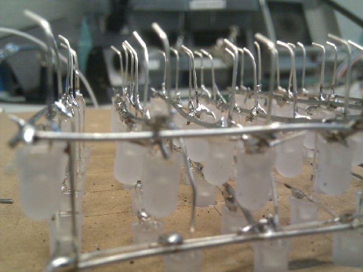
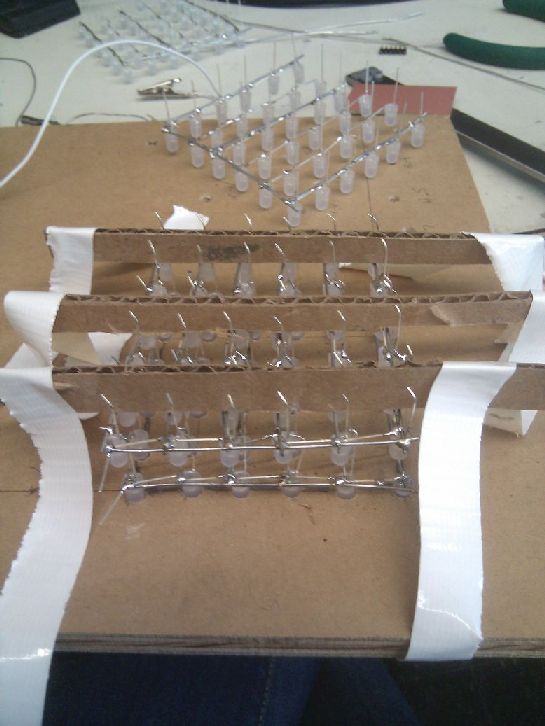
Layering
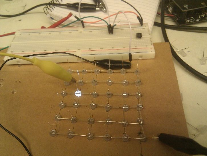
I used galvanized steel wire to reinfore some of the rows of LEDs. Specifically the lines around the edges, and one in the middle. I tried using aluminum wire, but then realized solder wouldn't stick to it. I bent the top (cathode) of each LED to connect with the next layer, then used carboard to hold the next layer while I soldered cathodes in each column together. I used the same method when making my 3x3x3 cube, but doing it on a larger cube was much more frustrating. I repeated this process for each layer, but didn't notice until the end that my cube was leaning toward one side. I should have been looking at it from multiple viewpoints during this process to make sure it was completely straight.
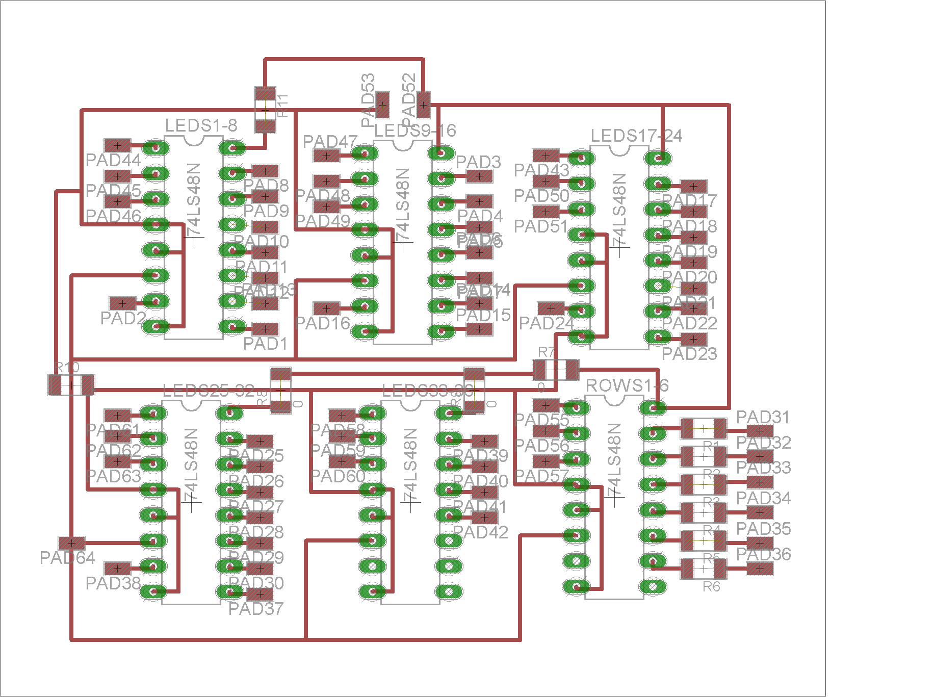
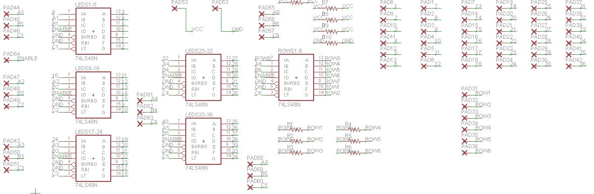
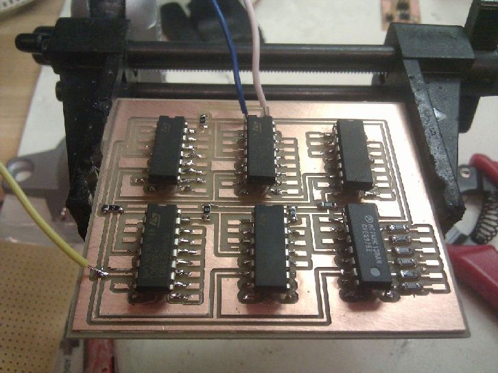
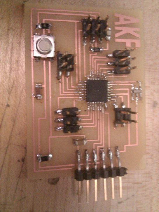
Circuit
I used 5 3-to-8 1-HIGH decoders to turn 15 outputs into the needed 36 inputs to the cube, and one 1-LOW decoder to say which layer should be put to ground. I decided to leave pads to directly connect wires to the circuit from the cube, but didn't realize how impossible this would be to actually create. My decoders were through hole components, so I just bent the bottoms to make them flat (initally I planned on drilling holes for them, but that seemed uncessary).
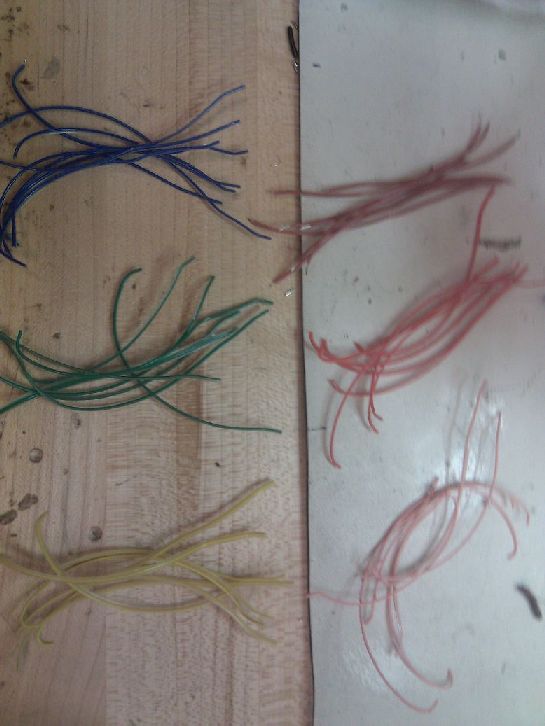
Getting all columns
I color coded my columns into groups of 8 so that it would be easier to connect them to the decoders. These wires are a bit too short to easily connect with the board though, as once you start connecting columns, the two boards become so close that it's impossible to wire all connections.
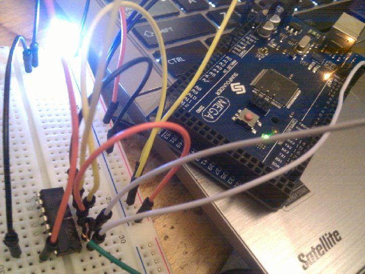
Fabduino
I tried using this fabduino design, as I needed at least 18 pins, but I could never get it to work. I tried multiple 328P's, checked every connection being made, checked voltages, and double checked my ISP worked. Eventually, my removing 328P's caused the small traces to come up, which I couldn't really see a way to fix. I decided I'd instead use the arduino to make sure my cube could work, and go back to using the fabduino once I had time to mill out a new one and debug it.
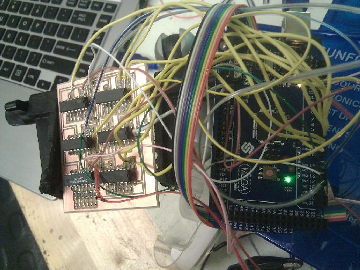
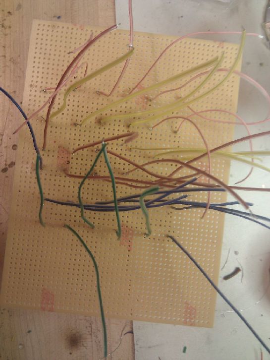
Testing and tangles
I tested just the decoders to make sure they could turn on an LED. I then started connecting columns to their place on my board...which became a nightmare. While connecting columns, I also tested again with the decoders. There were so many wire though, that it's very hard to get accurate readings, and many wires are about to come off the board, or are touching others, despite efforts to stop that from happening. I realized that I should have made my board with couplers instead, to organize the chaos a bit.

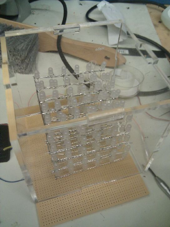
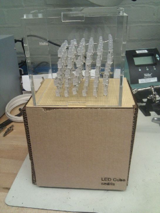
Acrylic Container
As an alternative to debugging, I made a simple press fit box for the cube out of acrylic. One insteresting idea Jasmine brought up is sanding the acrylic to give it a frosted look and disperse the lights.
Lessons Learned
- When dealing with so many wires, don't stick them directly to the board. That's just asking for trouble. Instead, use 2x5 or 2x3 headers to neatly connect wires from one circuit to another. This was probably my biggest problem. There are so many wires connected, that it's hard to really add any more, and it's very easy for a single wire to become disconnected.
- Use a more rigid structure for the cube. I first soldered the LEDs together, then added steel wire as extra support. But my LED leads were pretty short, so the entire cube came out much smaller than expected. I could have instead, directly soldered LEDs to the steel wires, for added support and flexibility in cube size. Another option that I really like, is what Dimitrios did by using surface mount LEDs, vinyl cutting a board, and taping the traces to something like cut acrylic. This gives a much cleaner, controlled design. If I were to make another LED cube, I would probably want to use his method, as it makes it much easier (well, maybe debatable with those tiny tinyl traces...) to make larger cubes and connect them to a main board. The biggest change I would make is using two surface mount LEDs back to back, to give a wider angle of light.
- You can't laser cut Lexan. Always look at allowed materials on whatever machines are being used! This was my first time cutting acrylic though, and I found it to be very fast and easy to do.
- Really understand what the final output will look like. When starting my cube, I thought having all of my columns being controlled by a single pin each would be fine. It wasn't until I was halfway through doing this that I realized it was much too chaotic to work with.
Next Steps
I didn't have time to get the larger cube working by presentations, but I aim to finish in the next couple days after it. I've learned that my soldering wires directly to the board was a very bad idea, that might work for smaller cubes, but won't work when there are 36 columns and 6 rows that all need a wire. Instead, I will use headers that split and connect to one row each. I'd also like to try a different fabduino design, and cut out a box out of slightly better material than cardboard. Looking back: although I made a 3x3x3 cube, I didn't test out all of my planned methods for the larger cube on it. I should have tested the smaller cube with my planned board, and realized that soldering wires would get hectic soon.