Output Devices
2D LED Matrix
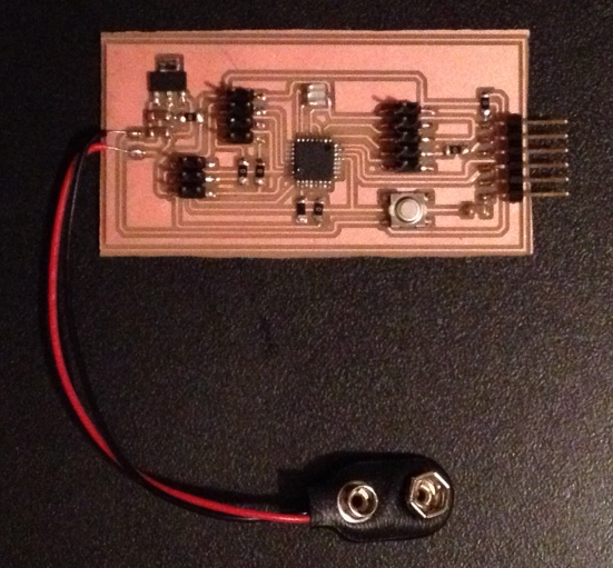
Note that the 4.7 uF capacitor between the output voltage pin of the regulator and GND is very important. Without it, the supply voltage is not stable enough to drive the external resonator to give a adequate clock signal. This comes up when the chip refuses to be programmed properly. Speaking of programming, the Arduino IDE can be used to program the homebuilt ATMEGA328P board. What is required is the appropriate boards.txt file, to be put in the [My Documents\Arduino\hardware\atmega] path. Then, the ATMEGA328P with 20 MHz external resonator will show up as one of the board options.
The other step to being able to program the homebuilt board is to load the bootloader first. This is done via the Tools/Burn Bootloader command. The FabISP is hooked up to the computer via its USB drive, and its six SPI pins are connected to the corresponding pins on the ATMEGA328P end. After the bootloader is done burning, the homebuilt board can be programmed via the USB/FTDI connection in exactly the same way as an Arduino Uno. The bootloader requires a HEX file, which is compiled from the corresponding C/CPP file. Note that on a Windows system, I have never been able to successfully burn the bootloader on to my board. It always gave a javascript error, which is not very informative since this is the language in which the Arduino IDE has been programmed. My only solution has been to ask a friend with a Mac to burn the bootloader for me. Even with the same boards.txt and the same HEX file, it works on a Mac but not on Windows, apparently.
One other Windows related glitch is that Windows 8 will not allow the user, even with administrator privileges, to change the Arduino program install folder, which is where the boards.txt file by default looks for the corresponding HEX file. This can be addressed easily by modifying the path and filename fields in boards.txt, but even with this trick the bootloader still does not burn!
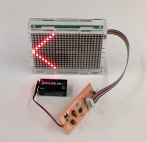
Below is an example of the LED matrix running, using the Adafruit library to draw lines on the board. The library has functions to draw lines, circles, points, or even characters!