Final Project
Bicycle Helmet-Mounted LED Matrix
1) Motivation
2) The LED Matrix
3) Press-Fit Acrylic Holder
4) Control Circuit with Wireless Radio
5) Wireless Controller
6) 3D Printed Helmet Mount
My final project ideas were finally distilled to the following: make a bicycle helmet-mounted 16x24 LED matrix. My
I had been leaning towards dedicated bicycle turn signal lights, since those would be a nice addition to the front and rear lights I already have. However, a quick search on Google revealed that most of the current options for signal lights involved a few static yellow LED's activated by switches connected via long lengths of wire.
There was one impressive device that caught my eye... a red LED matrix mounted to the back of a bicycle, and controlled by an Arduino board mounted on the handlebars. It is capable of displaying a wide range of signals on its 16x24 face, including regular red flashing lights, moving arrows to indicate turns, or even customized messages! I wanted to see if I could make a version that fit on a bicycle helmet instead of needing to be strapped down to a frame. I also wanted to make the control system wireless to eliminate the need to run long lengths of wire.
The LED matrix is available from Adafruit for $25. It can be controlled by three data pins on a ten-pin ribbon connector, in addition to VCC and GND. Adafruit supplies a useful library to help the user get started, and I described previously how to implement the code.
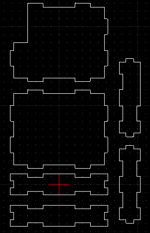
The LED matrix needs a holder, and since we are dealing with light, it needs to be transparent. I decided to make a super-snug acrylic press-fit holder for the device. To do this, I went back to the laser cutting tool from the start of the semester. This is the one overseen by Stan Coutreau and located in the physics department. After some trial and error with 10-mm-wide tabs, I found that 9.4-mm-wide slots were too snug, while 9.5-mm ones were too loose, so I went with a offset of 0.55mm between tabs and slots.


The circuit board I made to drive the LED matrix before includes an eight-pin header for a wireless radio. The header shares SCK, MOSI, and MISO pins with the header for the FabISP cable, but since they will never both be active, this is not a problem and saves some pins on the ATMEGA328P. This board can listen for serial transmissions from another source, and then display various signals on the LED matrix depending on what is received. So far I have not yet figured out how to read in serial with interrupt on the chip, so it is not always waiting for input, but can keep cycling an existing pattern until a new burst of serial communication is received. This also saves power on the other end, because it would eliminate the need for constant transmission.
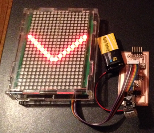
I already made a board with four push buttons (not including the reset for the chip) and the ability to transmit data out on a wireless radio. The push buttons go into the spare pins from the LED matrix board above, so the board designs are similar, and the same code can be loaded onto both boards. With this code, I have successfully tested using digital pin 8 (as defined in the Arduino IDE) to toggle between left and right-turn signals wirelessly.
The final element of my project is a holder to secure the LED matrix and associated electronics on a bicycle helmet. If I had all the time in the world, I would do something with molding and casting, but I decided as a shortcut to 3D print a custom piece for the purpose. It includes a slot for the LED matrix, an electronic bay (notice how nicely the battery fits in), and loops into which straps can be inserted to secure the mount to the helmet via the slots on the helmet surface. The base is flat rather than contoured, which is not ideal, but this can be alleviated with a bit of soft padding underneath. Moreover, I did not make the print very tall, to minimize 3D printing times. A more secure mount would be taller, and may even involve gluing the acrylic box in place (with only the top being removable). The electronics bay is also for now open to the air for easy access, and a more refined version would have it be both well-encapsulated / waterproof but accessible at the same time.


 <
<