Week 12
Networking and Communications
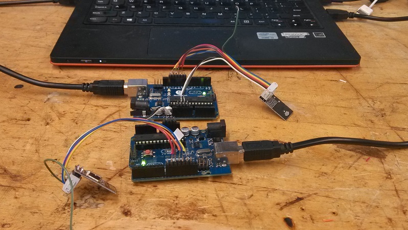
2.4 GHz Wireless Link
My goal was to wirelessly send a digital signal, e.g. the ON/OFF state of a switch, between two microcontrollers. This will be useful for my final project. The wireless mode of communication will be RF, which requires an impedance-matched antenna for maximum efficiency. The nRF24L01 is a compact board with chip + antenna all integrated, so that is what I set out to use.

There is a helpful tutorial that I followed. It (supposedly) includes a complete library of examples for the Arduino Uno, but I found the corresponding github archive to be mysteriously empty. Fortunately Nathan Melenbrink had already downloaded a copy, which I happily used.
I decided to try and run the RF24 wireless antennae using the example Arduino Uno library just to reassure myself of their functionality. The RF24's were connected to the Arduinos using 8-pin ribbon headers on the RF24 end, and by soldering to straight headers on the Arduino end, with pinouts as described in the tutorial linked above. Using the library was fairly straight forward--one either puts the files in the default Arduino library location, or one can put them in a personal folder and open an example file in Arduino. Note that the RAR file includes two levels of the RF24 folder. I found that if I kept both levels, the Arduino IDE got confused and could not find the right library files to include in a compile. Removing the duplicate, highest-level RF24 folder solved the problem. Also note that files in the default Arduino library folder are read-only. To save files that can be modified later, you must save them in another folder.

There were two issues with following the tutorial

1) With two antennae hooked up to two different active Arduinos (recognized as two distinct COM ports in the Arduino IDE), the boards would only talk to each other wirelessly according to the tutorial if they were BOTH set in transmit "T" mode--set one in "T" mode in the Serial Monitor, close the monitor, change to the other port under Tools -> Serial Port, open the Serial Monitor again, and set the second antenna in "T" mode. If one of the antennae is in "T" mode and one of them is in "R" mode, I got the error message

Now sending 2661...failed.
Failed, response timed out.

Not only did the ping-back feature not work, but the first "failed" message seemed to indicate that even the initial sending out step failed. The problem seemed to be traced back to the fact that I had bought a third-party "SainSmart Uno" instead of an Arduino Uno. The appearance was the same and the functionality ought to have been as well, but when plugging in a real Arduino Uno, the network functioned with one set as "T" and the other as "R."

2)The second problem is that when an actively transmitting or receiving board is unplugged from the USB power source, it does not resume transmitting/receiving once plugged back in again, which will be a problem for my project. This was actually due to an issue in the code. In the setup() function, there is a commented-out block under

//if ( role == role_ping_out )

However, if one looks under the condition for toggling between "T" and "R" modes,

if ( Serial.available() )

the commented-out block is actually important in setting things up for receiving or transmitting. In short, every time the board was powered down, it was reset in an initial condition that was neither ready for transmitting nor for receiving. The corrected code, for default "R" mode, is here. (These files cannot co-exist with the header and CPP files from the original R24 folder. If both sets of files exist, there will be duplicate errors.)
Now the antennae work as expected. In the screenshot above, we see the initial diagnostic printout in the Serial Monitor. The board is then set in "T" and starts transmitting properly. The receiver is unplugged for a few transmit cycles, leading to failed ping-back, but after plugging the receiver back in again, the transmission resumes as before.

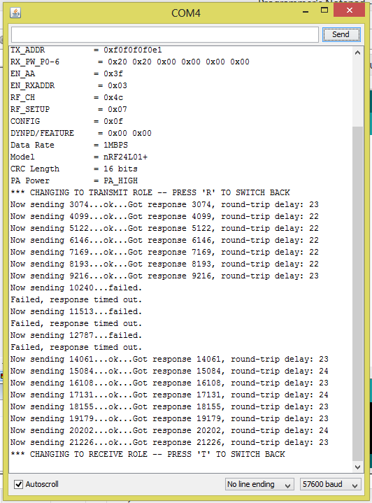
The final project page describes the implementation of these wireless radios with a home-built ATMEGA328P board (the same microcontroller as at the heart of the Arduino Duo).