Week 10
Input Devices.
Collecting Sleep Data via a 3-Axis Accelerometer
Introduction
This week's assignment was to measure something - add a sensor to a microcontroller board that I've designed, and read it. My goals were to create a custom breakout board with a 3-axis accelerometer, read the analog data from a Fabduino, and record my sleep activity over the course of one night.
Design
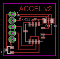
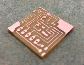
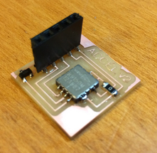
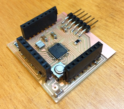
I designed a custom breakout board for the MEMSIC MXR9150MZ 3-axis accelerometer using Eagle. The breakout board features female header pins for easy access when prototyping with this board. A linear voltage regulator steps down the 5 V from the Fabduino board to the 3.3 V needed to power the accelerometer.
Since the part was not in the Eagle library, I learned how to add the new part to the library using this tutorial as a guide. The tutorial is pretty straightforward - to clarify, there are three different "components" of a new part that need to be added to a library. 1) Device: this refers to the overall part. 2) Package: for each device, you can have different packages (e.g. surface mount vs. through-hole). The package shows what the device will look like on your board. 3) Symbol: this refers to the schematic of the new part. Once you create a new package and symbol, you tie the two together when you create a new device.
Here are some exported images from Eagle, and the link to my schematic/parts:
Schematic
Parts

For the Fabduino, I used the design from this tutorial.
Make
Fabricating the 3-axis Accelerometer Board
After a couple of weeks of creating custom PCBs, fabricating and stuffing the board was straight forward. I used the Roland Modela MDX-20 to mill the PCBs. To get the Modela to mill the holes for the header pins, you can deceive the Modela by decreasing the mill diameter in the settings on the fab modules.
Below you'll see two versions of the accelerometer board. Only the second board works correctly.
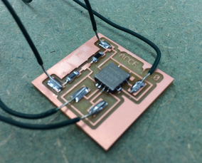
First attempt: In my lapse in thinking properly, I attempted to use a voltage divider to step 5 V down to the 3.3 V required by the accelerometer. This doesn't work! The accelerometer is a load that can be thought of as a "resistor" that draws power from the 3.3 V. As such, the accelerometer and the second resistor are essentially resistors in parallel, effectively rendering the "second" resistor of the divider less than intended. As such, the desired voltage ended up lower than the voltage I needed. Thanks, Rob, for the explanation!
Solution: Use a voltage regulator. There exist both linear regulators and switching regulators. Switching regulators are more efficient at handling power dissipation than linear regulators, but considering the low current draw from the accelerometer and the small step-down in voltage, a linear regulators will suffice here. I used the LM3480 3.3V regulator in the fablab inventory.
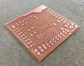
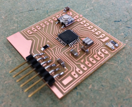
Fabricating the Fabduino
I followed a previous year's tutorial in making the Fabduino. Instead of using an ATmega168 chip and an 8 MHz external resonator, I decided to try my hand at using an ATmega328p with a 20 MHz external resonator.
By following Amir Lazarovich's guide to burning a bootloader, I was able to burn the bootloader on the ATmega328p. However, I could only program the board once, after which the bootloader appeared to be erased or broken. Only after re-burning the bootloader was I able to re-program the board. Thanks to Novysan, Matt, Nadya, Amir, and Oliver for helping me out. After many failed attempts at figuring out the problem, I decided to continue forward with programming the board with my FabISP, which worked without problems.
Measuring Accelerometer Signals
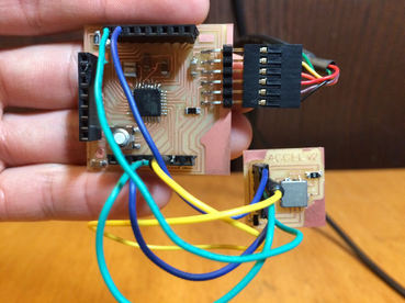
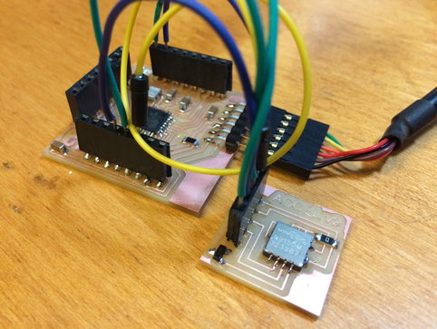
The accelerometer wired to the Fabduino.
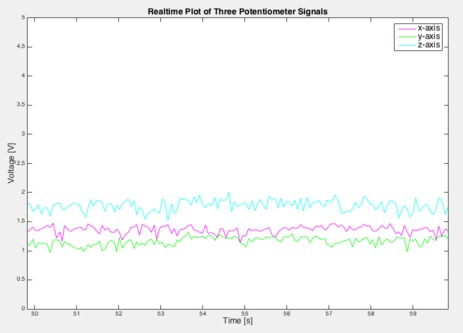
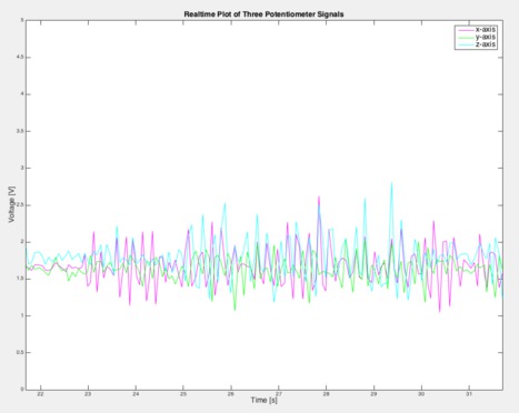
I used my same MATLAB code from prior weeks to plot the three analog signals coming from the 3-axis accelerometer. You can tell the difference between the working accelerometer board and the first board I made. Without enough power, the accelerometer outputs a very noisy signal, and does not measure any acceleration. The working accelerometer board measures signals with less noise.
Failed accelerometer board. Lots of noise. No pickup of input signal.
Recording Sleep Data
Below are the data recorded from one night of sleep. I placed the accelerometer in a small box underneath my pillow. I still need to investigate the sensitivity of this particular accelerometer and determine if anything useful can be determined from the collected data. Keep posted for more analysis...
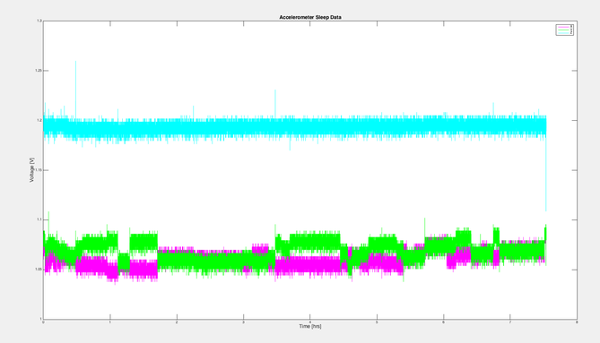
Data from 3-axis accelerometer over ~7.5 hours of sleep.
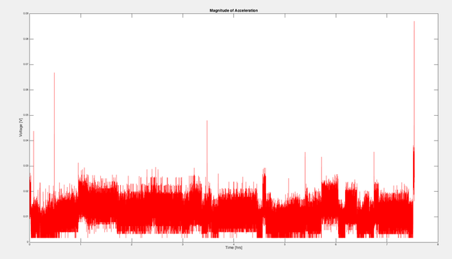
Magnitude of acceleration vector plotted over the ~7.5 hrs.
Lessons Learned
1) The best way to step down a voltage is to use a voltage regulator. A voltage divider will not work as intended.
2) Bootloaders can be very finicky. There is a lot that goes into burning the bootloader, and I plan to take more time in the future to understand the underlying configurations (e.g. setting the fuses for the bootloader, compiling the bootloader hex file, etc). In the meantime, I am sticking to using the FabISP to program my boards.
3) Female header pins are very useful. Rob is ordering a batch that will come in for the upcoming weeks. Although they are not a permanent solution, they are very useful for prototyping - jumper cables can quickly be attached/detached.