Week 11
Output Devices
Potentiometer-controlled Servo Motor
Introduction
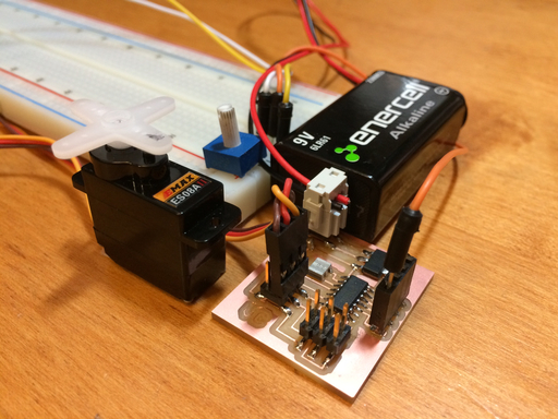
This week's assignment was to add an output device to a microcontroller board I've designed and program it to do something. My goal was to fabricate a custom driver for a servo motor and program the driver such that I could control the servo using a potentiometer.
Design
I used CadSoft Eagle to design the driver for the servo motor. The design includes female header pins at four ADC input pins for interfacing with other devices - in this case, a potentiometer used to control the servo. Below are the links to the schematic and pictures of the board design. The schematic shows a +12 V supply, but I ended up using a 9 V battery, which is sufficient for the 5 V regulator to work.
Schematic


Make
Fabricating the Driver

Straightforward - no problems in fabricating and stuffing this board. I used the Roland Modela MDX-20 to mill the PCB.
Programming the Board
This was the main challenge. I had to learn how PWM controls the position of the servo motor. Servo motors are driven by signals with a frequency of 50 Hz (a period of 20 ms). To control the position of the servo, we need to send signals to the servo that are on for a certain duration (typically around 1 to 2.5 ms). In this case, we will use the phase and frequency correct PWM mode.

The above diagram shows a phase and frequency correct PWM signal. The counting is both in phase and symmetric with respect to the output signal. The PWM signal is generated by the timers onboard the ATtiny44. By setting the OCnx bit, we can control the on duration of the signal. By controlling the TOP value, we can control the overall duration/frequency of the signal. In our code, the OCnx bit is set by OCR1A, and the TOP value is set by ICR1.
Given the ICR1 setting, how do we know what OCR1A value corresponds to what position of the servo motor? This is where the ATtiny44 datasheet really comes in handy. The following equation from the datasheet describes the relationship between the frequency of the signal set by OCRnx, the value of the OCRnx bit, the clock frequency, and the prescaler value.

Since I am interested in calculating OCRnx, I solved for this variable to get the following equation:

Great! So I have OCRnx, but how do I convert a potentiometer signal into the desired OCRnx value? I decided to set the full range of the potentiometer signal to correspond to the full range of the servo motor. Using a bit of algebra, I get the following equations:

c is a conversion value. f_high and f_low correspond to the range of PWM frequencies needed to attain the full range of servo motor positions. N_ADC refers to the number of bits of the ADC value. f_OCRnx is our desired frequency, and val is the ADC value.
At last, I combined all the pieces into some C code. The order of operations is as such:
1) Obtain value of potentiometer signal using ADC.
2) Calculate desired PWM frequency (f_OCRnx).
3) Calculate and set the OCRnx bit.
Each time the OCRnx bit is set, the ATtiny44 outputs a PWM signal corresponding to the desired position!
You can find my code at the GitHub repository below, including Makefiles. I used servo_driver.c to determine the PWM signals needed to obtain the full range of my servo motor. I use servo_control.c to control the servo with a potentiometer.
Glitch?
Interestingly enough, the servo motor can only be controlled if the FabISP headers are connected to the driver. If these headers are not connected, the servo displays twitching behavior and cannot be controlled by the potentiometer. I believe the glitch disappears if the GROUND pin of the ISP header is attached, but I have not confirmed this completely yet. See the video below:
Lessons Learned
1) The datasheet is extremely useful - although it took some Googling to understand some jargon, I was able to successfully implement equations listed in the datasheet for calculating desired PWM frequencies.
2) Be careful with declaring the proper variable types in C. I initially was unable to drive the servo motor b/c I was doing math with incompatible types or declaring types too small to store certain values.