Week 15
Final Project
FabBot Segway/Land Rover
Introduction
I decided to completely switch gears and make a balancing robot/land rover. It's like a mini Segway with a twist, featuring more than one mode of operation. I was reading up on control theory a couple weeks ago and looked at the classic inverted pendulum example, which got me excited about balancing robots. The idea is to use a controller to maintain an inverted pendulum - robot in this case - at the position of 90 degrees from the horizontal. An IMU reads the robot's linear acceleration and angular velocity. After applying a Kalman filter to the data, a PID controller determines the needed motor output to correct for any errors in the robot's position. When the robot senses its orientation is near the horizontal, it will switch to the second mode of operation - land rover mode.
Design
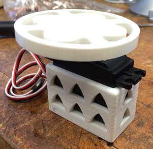
I wanted to make the robot completely press-fit, with pieces fabricated using a combination of 3D printing and laser cutting. No need for traditional fasteners: screws, nuts, and bolts.
Electronics
I designed the boards in CadSoft Eagle, with any necessary editing done in Inkscape. The board handles everything on the robot - reading data from the IMU, running the controller, and sending PWM signals to the servo motors. I followed Amanda Ghassaei's tutorial to mount the gyro and accelerometer, which requires the use of a 10 mil endmill and some different soldering techniques! A big thanks to Amanda for also helping out on multiple occasions during this project, providing the necessary components for making the IMU.
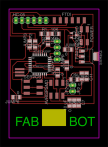
The important parts used on this board are an LSM303 3-axis accelerometer, ITG-3200 gyro, ATmega328p chip with 8 MHz resonator, and HC-05 bluetooth module. It is important to note that the sensors are 3.3V devices, so I designed the board to run at 3.3V. Only the servo motors are powered at 5 V using a battery as external power supply.
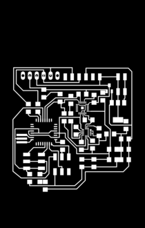
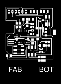
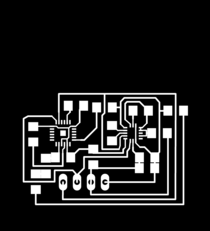
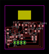
For my first design, I took an existing Fabduino design and added the sensors - however, this proved to be too bulky and complex if debugging was necessary. For my second design, I just designed the board from scratch to make it compact and fit with my robot. Below are the schematic and images.
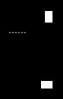
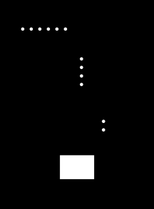
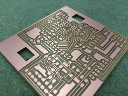
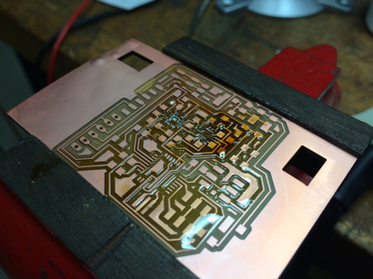
I exported all images at 2000 dpi just to make sure the fab modules could pickup the details of the 10 mil traces. 1) Mill board with 1/64" end mill, 2) use 0.010" end mill for fine details, 3) mill holes with 1/32", 4) mill outline with 1/32". ***For Step 3, it is necessary to invert the image for milling holes. When using fab modules, check to make sure there are no shorts - I had to cut out some shorts with an exacto knife after milling one of my boards.
Schematic


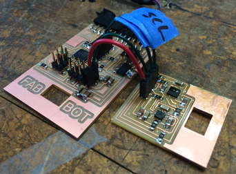
Had a lot of problems with this board, which will be explained below. Third Design: I then designed two separate boards for convenience and facilitating troubleshooting. One board holds the IMU sensors, the other board holds the ATmega328p microcontroller.
Main Board:
Main Board - Schematic

IMU Board:
IMU Board - Schematic


Chassis
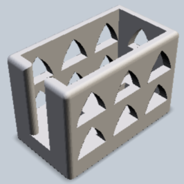
Motor Mounts:
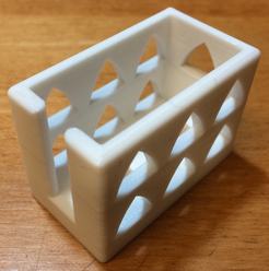
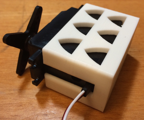
I first designed parts to enclose the servo motors in SolidWorks. The arch-shaped holes were added to save material and printing time. I chose the arch shape to make the object 3D-printer friendly - the arches feature an overhang angle that won't cause the layers to fall using the Makerbot. Two holes on the bottom press-fit onto the main body of the robot.
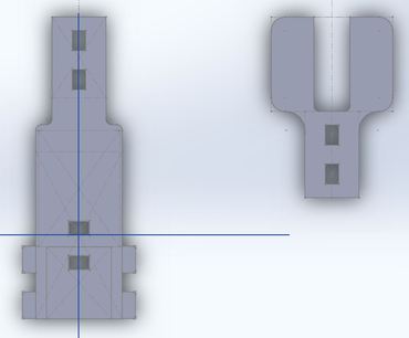
Main Body:
I used the master modeling approach to build these parts, which was crucial for going back and adjusting the parts when the tolerances were off. Here is the main body of the robot. The surfaces were exported as DXF files for laser cutting.
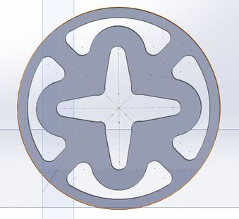
Wheels:
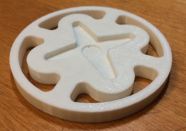
Since I wanted everything to be press-fit, the wheels were slightly tricky. I wanted to attach the wheels to the servo motors without altering anything. Fortunately, Solidworks has a useful feature - you can import an image and create a sketch from the image. I took a picture of the outline of the servo horn, and modeled the wheel based off this. The 3D-printed object snaps right onto the servo horn.

Make
Electronics
Below is one of my PCB designs, milled on the Roland Modela MDX-20. First, I milled the majority of the traces using a 1/64" endmill. I then nervously went in with a 0.010" (10 mil) endmill around my accelerometer and gyros. Surprisingly, I was able to get the 10 mil traces to work on the first try - do make sure to use a lower speed (2mm/s, NOT 4 mm/s) and make sure your board/sacrificial layer are as flat as can be. The only problem I ran into was actually not milling enough area around the accelerometer and gyro - I post-processed with an exacto knife to cut some shorts.
Electronics
I had lots of trouble programming my second PCB design after stuffing - sometimes I could program the board, other times I could not; I suspect some shorts (e.g. I was measuring 0.84 V at a 3.3V output at the regulator). Since the board was so complex with the addition of the IMU sensors, I ended up splitting the microcontroller as a separate board from the IMU sensors as you saw in the design section above.
Attempt #2:
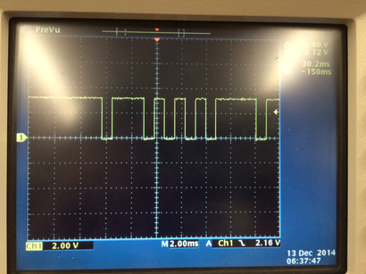
I made my third PCB design, programmed it, but nothing showed over serial! Looking at the scope with the help of Nadya, we determined that the signals were way too slow. Turns out I had not set the fuses - I burned the bootloader, and I got a very relieving "Working Program!" over serial.
Board Settings:
- Board in Arduino IDE: Arduino Pro or Pro Mini (3.3V, 8 MHz) w/ ATmega328
- USBtiny programmer (FabISP)
- Burn bootloader to set fuses
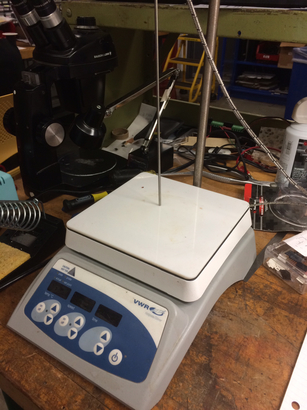
Regarding the IMU Board: Instead of using a heat gun technique like I did in my first board, I decided to try using a hot plate to reflow solder. Using an empty test board, I pre-tinned the 10 mil pads on the sensors, and applied generous amounts of fresh flux from Radio Shack. Turns out that the FR1 boards burn before the temperature reaches the melting point of Sn63Pb37 solder (~361 deg F), and I ended up generating a lot of smoke - sorry Harvard section!
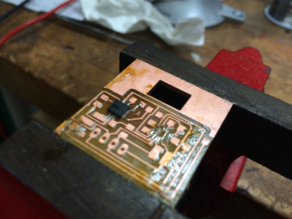
Abandoning the hot plate idea, I returned to heat gunning - as you can see below with the tiny ITG-3200 gyro on the IMU board. Lots of gunk build-up! I believe it is from the flux hardening - it tends to harden if the heat gun is applied for too long. This particular attempt failed. Shorts!
Many Attempts Later...
Initially, I was using the heat gun on both the gyro and the accelerometer, because I thought they were both Quad Flat No-lead Packages (QFN). That is, they only have leads on the bottom. However, the ITG-3200 gyro package I had actually has leads that wrap around the sides - placing the board under a microscope and using flux, I was able to solder the leads without using the heat gun. Unfortunately, I still needed the heat gun for the accelerometer.
I practiced several times on empty boards, until I found a good technique that worked. For one, it is important to know that these components should not be heated for too long, and that solders have recommended heating profiles that minimize the formation of oxides and optimizes bonding.
Step 1: Apply flux to the area around the 10 mil pads.
Step 2: Lightly pre-tin the pads with solder where they will connect with the QFN package component. Tin a trace nearby, which will help determine if you have reached the desired temperature with the heat gun later.
Step 3: Apply flux to the QFN component and place onto pads in desired alignment. Apply more flux.
Step 4: Apply heat gun. I slowly brought the heat gun down over about 20 seconds, hovered over the component at about 1-2 inches from the component, moving the heat gun in circles around the component to distribute heat evenly. This step should take a short time, around 10 seconds; once you see the solder become shiny, you know the solder has melted - nudge the component into place if it is out of alignment (this can be extremely frustrating, but be patient). I then brought the heat gun away from the board over the span of another 20 seconds for slow cooling to prevent any warping.
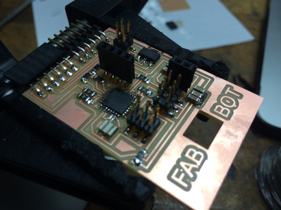
AT LONG LAST, WORKING BOARDS:

Albeit gunky, the IMU board works!
3D Printing
Settings Used on MakerBot:
- PLA Material
- Standard Resolution
- 10% Infill
- 3 Shells
- 0.20 mm Layer Height
- No supports/raft needed
Servo Enclosures:
Here are the 3D printed parts to enclose the servo motors. Each part took about an hour to print. Although the tolerances are a little smaller than desired, the servo motors fit into the parts without much effort.
Servo Wheels:
Here are the 3D printed wheels - with a little bit of filing, the wheels snapped right on to the servo horns!
Laser Cutting
Using the Kern laser cutter in the Harvard Physics Machine Shop, I cut the parts for the chassis of the robot. I exported DXF files from SolidWorks and imported them into CorelDraw on the laser cutter's computer.
Settings Used:
- 0.25" acrylic material
- 1 pt line width. I designed the parts with a 0.003" tolerance between tabs and their respective holes. However, it turned out that leaving the line width at the default 1 pt line width in CorelDraw provided the perfect tolerances for the robot. I will note that the laser had problems cutting through the acrylic perfectly straight - some of the holes have slightly angled walls.
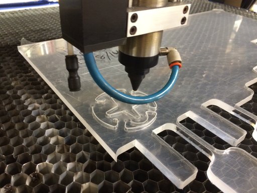
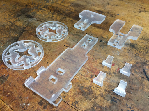
All the pieces after laser cutting!
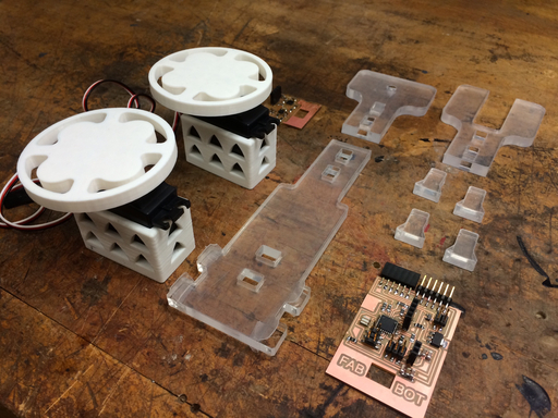
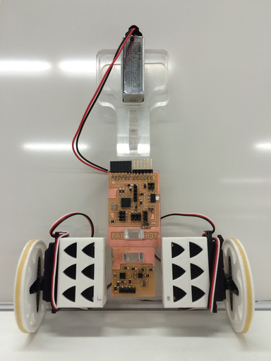
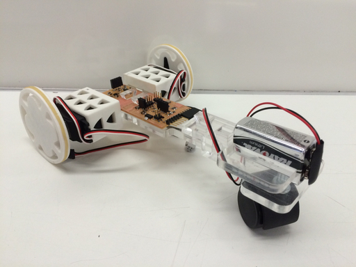
All the fabricated components of the robot.
Programming - Input & Output Devices, Communications
My steps were as follows: 1) Read data from the accelerometer and gyro and calculate robot's orientation, 2) drive the servo motors, 3) filter the data, 4) apply PID controller, 5) test robot and calibrate parameters.
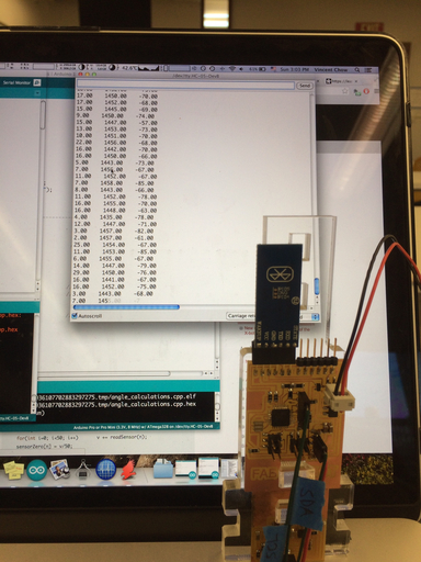
It has never felt so good to see data streaming over serial port. Using code provided by Amanda's tutorial, I tested to make sure that I could talk to the gyro and accelerometer via I2C communication. What you see below is an image of the robot sending data via Bluetooth to my computer.
Driving the Servo Motors:
Fortunately, I played around with driving servo motors in output devices week, and I applied this knowledge to driving the continuous servo motors. Continuous servo motors are essentially DC motors with a gearbox. It became very popular in the hobby community to hack traditional servo motors to rotate continuously, that they are marketed as such. A PWM signal controls the velocity of the motor instead of position.
I used the ATmega328p's 16-bit timer to output PWM signals from the PB0 and PB1 pins in the phase and frequency correct mode. ICR1 = 20000 sets the overall period to 20 ms, and OCR1A or OCR1B sets the on time to some value between 1.3 and 1.7 ms (the range of controlling the servo motor).
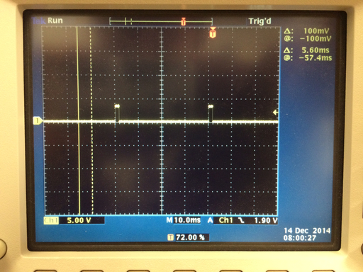
I first calibrated the Parallax Continuous Servo Motors. According to the datasheet, the motors are calibrated by applying a 1.5 ms PWM signal and turning a potentiometer dial until the motor stops moving. As you can see from above, I checked a scope to confirm I was getting a 1.5 ms PWM signal, and then calibrated the motors.
Data Filtering and PID Controller:
With the help of this very helpful balancing robot example, I implemented Kalman filtering and PID controller. The Kalman filter removes the noise from the raw accelerometer and gyro data to obtain cleaner data on the robot's orientation. By reading the error between the robot's current orientation and the desired orientation, the PID controller calculates the needed output to reduce this error to zero. It does so by taking a look at the current error (Proportional term), past error (Integral term), and predicted future error (Derivative term).
You can take a look at the overall code running the robot at my GitHub Repository.
Below is a video of the first test in putting all this together. The PID controller still needs a lot of fine tuning!
Balancing FabBot Test from Vincent Chow on Vimeo.
FabBot Segway/Land Rover from Vincent Chow on Vimeo.
The PID controller doesn't work as well as I would like, but when the robot is tired of attempting to balance, it can happily switch to land rover mode and explore its surroundings.
Lessons Learned
1) Triage, divide, and conquer. Plan AT LEAST a week in advance. I did not do this, as I really didn't settle on a final project idea until two weeks before the deadline - this is a bad idea.
2) It's a good idea to test connections using a multimeter BEFORE applying power to your board. I double checked to make sure I didn't have any shorts between VCC and GND.
3) Wire jumper resistors in series in CadSoft Eagle so you can use DRC/ERC to check for errors later. Do not add unattached jumpers on the board, which will make it difficult for troubleshooting afterwards.
4) Watch out for shorts due to milling errors, simply from not having large enough spacing between traces/components. With complex boards, this is easy to go unnoticed - using a multimeter to check for shorts after soldering each component may be a good idea.
5) For something that needs as much precision as QFN components, using a heat gun may not be a good idea. It's difficult to match the recommended heating profile, and often times than not, I overheated my boards, stressing the components as well as producing a gunky mess of hardened solder flux.
6) Use solder flux for anything tricky/small leads! This substance is a bit messy but super useful. The solder goes to exactly where it needs to go.
7) PID controllers can be very difficult to tune, particularly for a non-idealized inverted pendulum with the mass distribution that my robot has. Given another chance, I would redesign my robot by considering the dynamics of an inverted pendulum first.