Week 6
Electronics design
Redesigning Hello World
Introduction
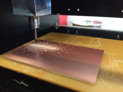
This week's assignment was to redesign the Hello World board and add at least an LED and a switch to the board. I redesigned the board in Eagle and milled the printed circuit board on the Roland MDX20.
Design
Once I learned the basic functions of Eagle, I could quickly go from designing the board to fabricating it. I particularly like Eagle because there is a command-line interface. Once you know the right functions to use, they can be easily called for use. Here is a list of common commands I used while designing the board:
Schematic Commands -
- move: move parts (right click to rotate parts)
- add: add parts from the library
- delete: delete parts from schematic
- net: connect parts
- label: label nets extending from parts
- name: edit the names of labels
- value: provide a value for components (e.g. capacitors, resistors)
Board Commands -
- move: move parts
- route: draw traces connecting parts
- wire: use this to draw the outline of the board
- ripup: useful for removing routes
- export: export file for printing
- grid: change size of grid to which parts snap
Import Libraries
1) By default, the libraries are placed into the $EAGLE/lbr folder, where the $EAGLE directory is where you downloaded the Eagle software. Download the library you wish to use, and place it in this folder. You should see the new library in the Eagle control panel. Right click the library, and click "Use" - there should now be a green dot next to the library's name.
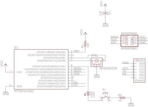
Draw Schematic
2) Create a new project, and then create a new schematic. The best practice is to complete the schematic before attempting to draw the board. Place parts by using the "add" command. Navigate to the library containing the desired part, and choose it. To connect parts, you can use the "net" command. To simplify the schematic and prevent criss-crossing nets, you can extend a net from a part, label it, and change the name to match that of another label. Eagle will automatically ask whether you want to connect those nets. Once you've completed the schematic, you can create the board by typing "board" in the command-line.
Draw Board
3) Using the "move" command, place parts where you would like them on the board. Make sure that the dimension for your board is correct. Ideally, the connections between parts should be as short as possible.
Prepare Files for Milling
4) Exporting the files properly is important. Eagle exports files with the dimension lines as the border of the entire image. However, we need an extra margin of black so the fab modules can calculate paths correctly.
To make the outline properly, use the wire command and place a border inside your dimension lines, but around your traces. The space between dimension and outline should be more than the width of the toolbit, or else the fab modules will not calculate a toolpath. These lines should also be in a layer besides your top and dimension layer (e.g. bottom). Make sure there is enough margin between this line and your traces, b/c the 1/32" endmill will cut along this line.

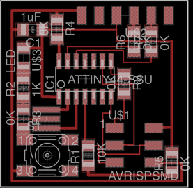
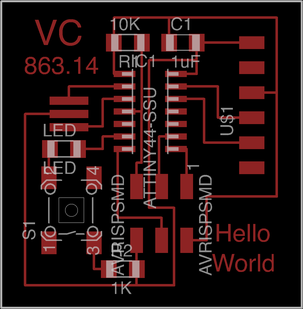
Example where the outline (blue) is inside the dimensions (white), but safely outside the traces.
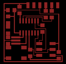
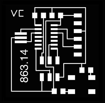
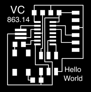
Now display only the traces, and export a png at 1000 dpi in monochrome. Then, display only the outline, and export a png at 1000 dpi in monochrome.
Lastly, take the outline png and fill in the black interior of the white outline in software such as Inkscape or Photoshop. Your files are now ready for processing in the fab module.
Make
Round 1
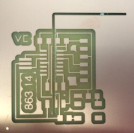
I designed my first board by completely moving around the parts, and the routing proved challenging. The example hello world seems to be designed pretty well, and I had trouble routing without the use of several jumpers, which is not ideal. Here is what a bad board looks like:
Jumpers everywhere!
Round 2
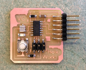
I redesigned the board without the use of jumpers. I utilized an LED connected straight to the voltage supply as opposed to one of the microcontroller pins, not taking into account that we would program these boards in future weeks. However, I got a chance to check and make sure I had wired the LED properly. Here is the LED in action!
Round 3
I redesigned the board, this time connecting the LED to one of the pins of the ATTINY44. Unfortunately, the traces did not turn out so good this time around. The 1/64" endmill had broken since last time I used it, and the newer endmill cut off more material - as such, my 10 mil copper traces popped right off the board!
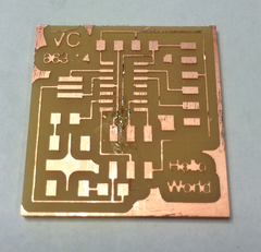
Where'd all the traces go!?
Round 4
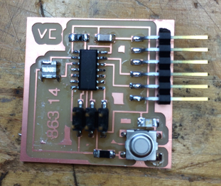
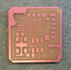
Back to the drawing board - I made the traces thicker (14 mils), and the board came out just fine.


Lessons Learned
1) Take into account the life cycle of the endmills. Newer endmills will cut out more copper material, making it more difficult to get smaller traces.
2) Optimize board layouts by minimizing distance between parts. It also helps to provide easy access to power supply. On my board, this means providing a trace to ground near the exterior of the board.
3) It is easier and safer to export the board layout and outline straight from Eagle. I ran into an issue with creating the outline in Inkscape, resulting in the modela cutting through a perfectly fine board. Exporting the layout and outline from Eagle ensures that the image dimensions are correct.
4) For board outlines, if there is not enough margin of black between edge of the image and the outline of the image, the fab module will not calculate a toolpath. Although it is best to go back into Eagle and fix your outline, you can fool the fab module by inputting a smaller toolbit size (e.g. 0.4 mm instead 0.79 mm).