Bike Saddle
06. Modling and Casting
This week was an exciting week because it was a unique way to get insights into molding and casting adn actually make some steps forward for the final project, that changed from being a self-rotation microgravity exercise device to a smart bike seat that can warm up during winter and control bike lights. The inspiration from this project came simply came from the facts that:
- Winters are cold in New England
- Winters are dark in New England
- I always forget to turn on and off my bike lights
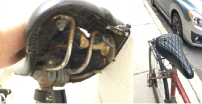
- My bike seat is really falling apart
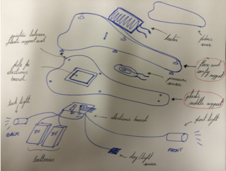
I thus wanted to use this week to create my bike seat. In my early design, the seat will be essentially composed of different parts (from top to bottom):
- Fabric cover
- Heaters
- Comfortable flexible layer
- Pressure sensor
- Hard plastic layer
- Electronic Board
- Metal interface with the bike
So this week was interesting for two things: the comfortable and flexbile layer and the hard layer. I started looking at existing CAD models for bike seats. I chose the one the most appropriate and started to work on it both in Rhino and Solidworks: removing the metal rails on the back, adding the mold. A good tutorial for Molding and Casting can be found here . I quickly encountered design issues because of my limited skills in Solidworks and Rhino in terms of Boolean operations and creating molds. The bike seat is also actually a complex geometry and it requires a lot of thinking to imagine the molding. I came up with a conclusion, that, for this week, I will focus on the flexible part. As the bike seat is a little big, I would create the mold from MDF and the paint it to have a smooth surface, and actually cast the OOMOO Silicon Rubber , as the flexible part. The difficult part was really the Computer design.
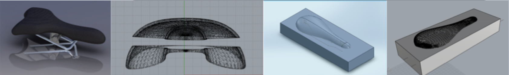
Having tried some Molding options in Solidworks, I finally cam back to Rhino. Thanks to the TA who was here to help me A LOT, the worflow was:
- I made a Boolean difference between a cutting plane and the "positive" saddle ("cutPlane" in Rhino, but also see :"Section" function)
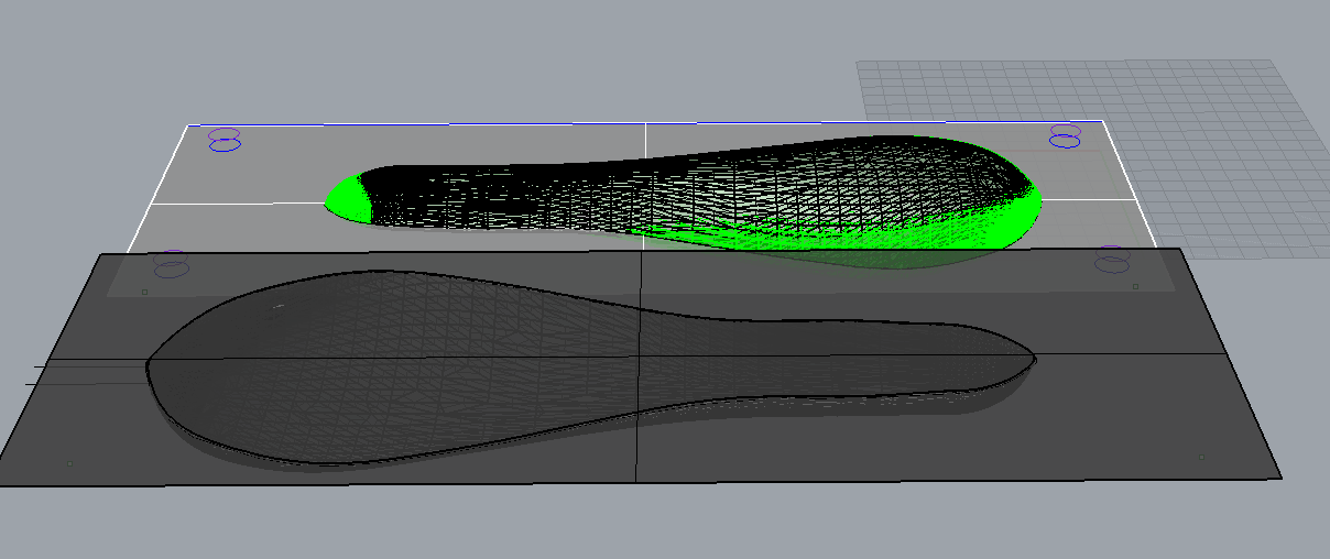
- I then trim the saddle to have one perfectly horizontal section because it would have been not really possible to 3D cut the underlying part otherwise. That left me with only one surface of the saddle
- I then offset the surface by 5mm, being the surface I wanted. It actually worked but once in Mastercam, the surface created was damaged and thus I used a different technique, copying and pasting the same surface but scaling it. It is a different operation but it was fine for this first trial.
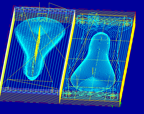
- I assembled 3 layers of MDF with 1/2" thickness and created a control plane to show upt to where the machine will cut.
- I did a boolean difference between the saddle surface and the plane for the bottom mold and the top mold
- On the bottom mold where the surface is carved down, I added two ways to the surface: one to pour the cast, one for off gazing. I also added alignment cylinders to make sure I could align the different molds.
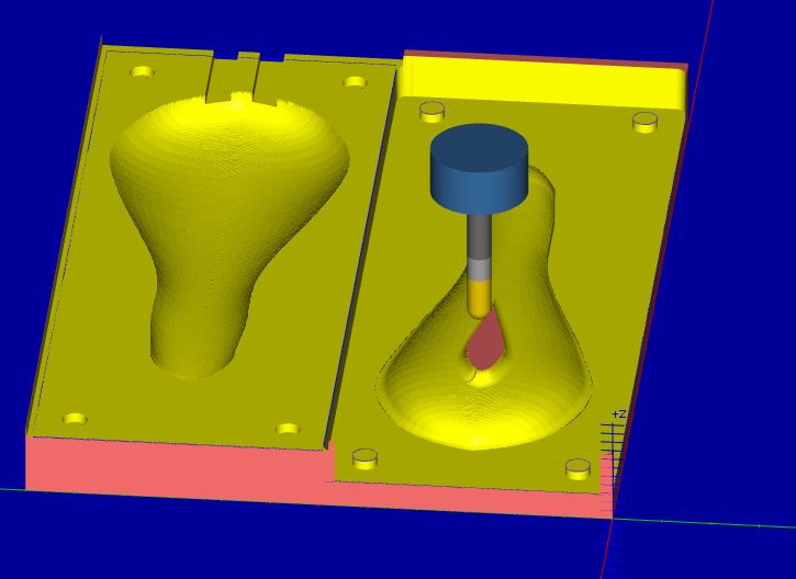
I then exported the file in Mastercam and started with playing by with the layers to set up the tool path and speed. I use two type of tools: the 1/2" flat end tool to cut the plane surface, the holes, and the 1/2" ball end tool to mill teh surface. What is particularly important is the feed rate that can be found here . I then needed an operator of the ShopBot to help me check the file and run the machine.
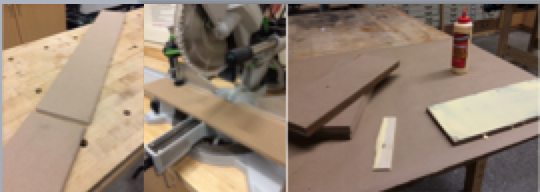
Meanwhile, I actually started to assemble the MDF parts to be 3D milled and that would be painted to create the mold. The workflow consists in cutting the different layers and then to glue them. The glue has to dry over a night, and then is ready to be 3D milled with the Shopbot machine. It was fun because I got to use different electric saws and do something I did not do previously.
The story is actually much longer than it appears. After the MDF slept overnight and was glued, the next step was to 3D mill it with the Shopbot. I started screwing on the table the three layers of MDF (not easy) and to prepare the file. When I realised that I could not actually used screws because I would mill the all layer. One night lost. To unscrew the screws was actually really not easy and I had to actually cut some part.
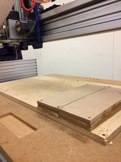
The next step was then to go to N51 to the Onsrud machine. The Mastercam files had actually to be modified to the new machine. We ran a first run and it actually failed because the machine was creating too much torque on the MDF and was thus detaching the whole MDF from the air succion of the table. Another night lost. A third attempt was then to glue (again !) the MDF to another larger piece of MDF that would cover more surface and then keep the stock in place. We needed to adjust all of the Mastercam file to a higher stock. Once it was done, we ran a first try, and it failed again. The torque was still too hight. We tried to run it at a slower pace but it failed too. Finally, we change the mastercam file to cut the first flat surface with more paths and less depth for each depth. It succeeded ! FINALLY ! The only issue is that the first failed actually cut the whole stock ans left a trace that was undesirable.
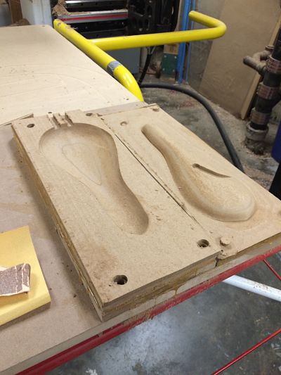
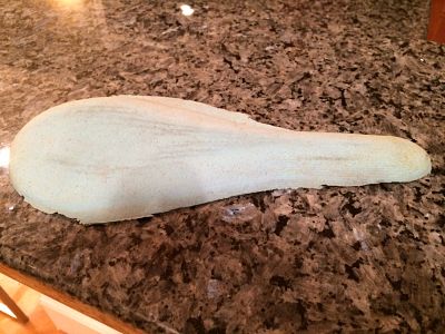
I then had to paint it and to wait overnight because the MDF is really absorbing a lot of fluid I could not cast the OOMOO directly.
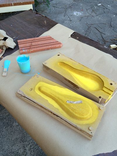
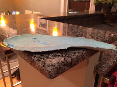
Finally, I tried to fill the cut with some paper with an approximate good shape and prepared the OOMOO mixing the two silicon rubbers together. I waited 7 hours because it was the long OOMOO, and finally I had my saddle. I was pretty happy about it, since it has no holes and I can actually use it for the final project. Next step is maybe cast a hard part to attach the OOMOO cover on it.