Speaker
09. Ouput Device
The goal of this week was to make a speaker as an output device of a board. Ideally, I wanted to record a short audio prompt and to play it on the speaker. A possible application is to implement the speaker in the small bike seat project. When the seat feels (with the help of accelerometers and gyroscopes) that the bike is tilted because someone has put it down, it starts playing the recorded voice asking if it is posisble to put the bike back in a normal position. Another option is to have a welcome pre-recorded message when someone seats on the bike seat. In any case, I could have used to types of boards to make these speakers: a basic speaker board using a MOSFET and a H-bridge board, that allows a better modulation of the speaker and thus has a higher fidelity than a simple speaker board. The simple speaker board uses the MOSFET to modulate the coil, but can only "pull" the speakers. It thus distort a little the sound because we cannot push and pull. It uses class D amplifer to seperate power and command circuits. The H-bridge is mostly used to control a DC motor (we want to be able to control it in the two directions) and thus allows us to uses it with a speaker and to be able to "pus" and "pull" the speaker, thus giving a much higherfidelity of the sounds. The following pictures show the board for the simple passive speaker (left) and for the H-bridge (right).
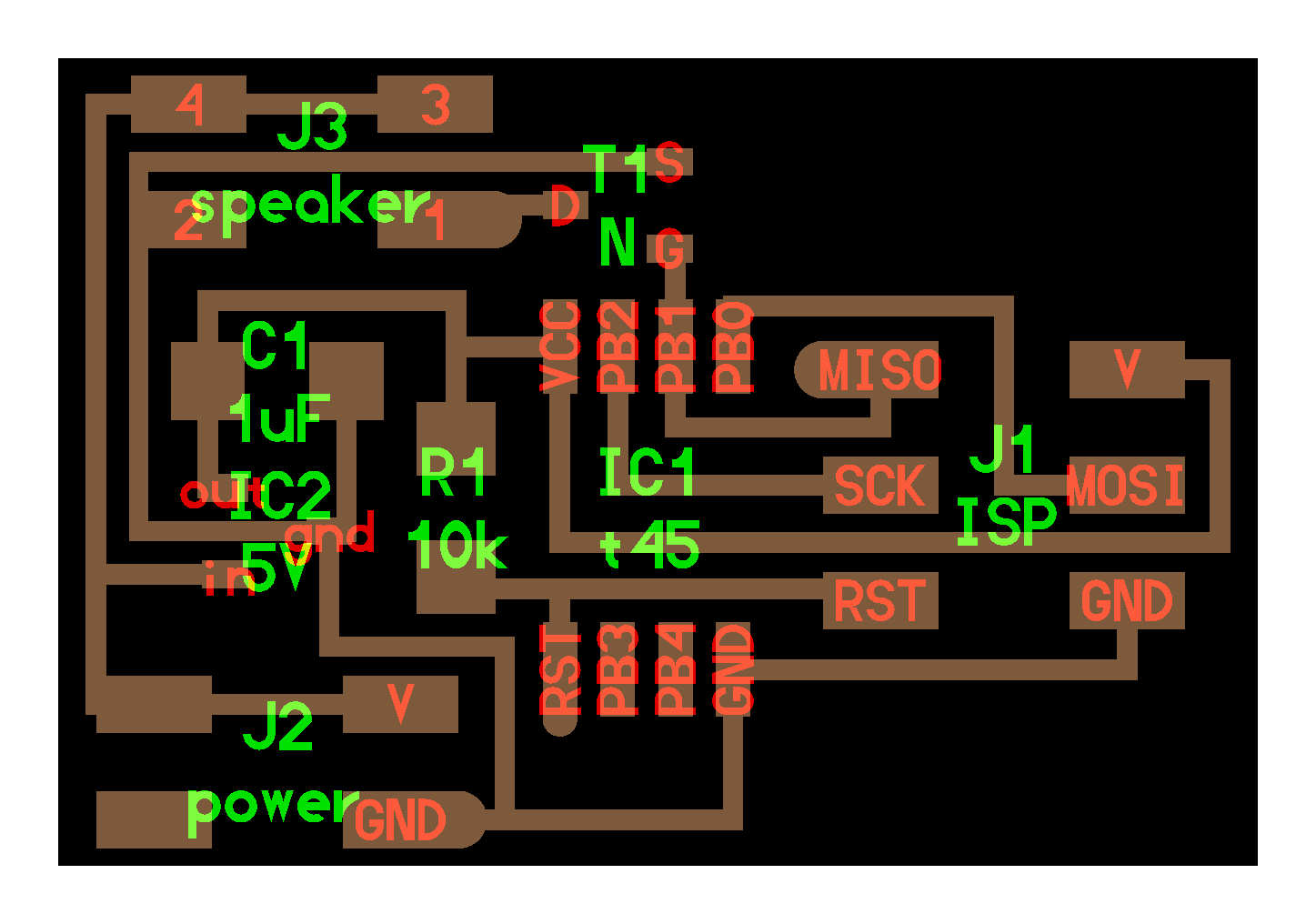
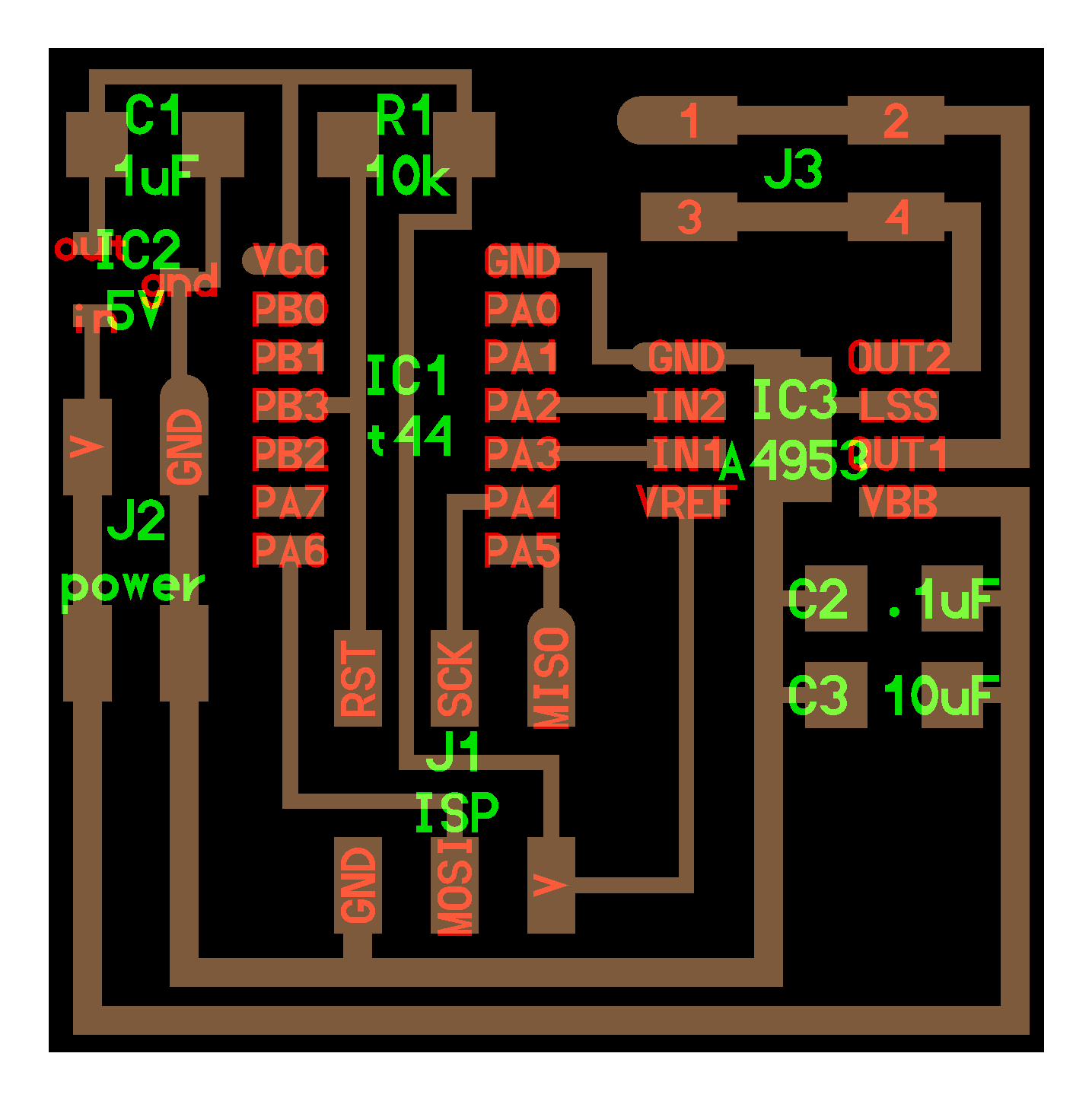
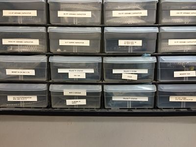
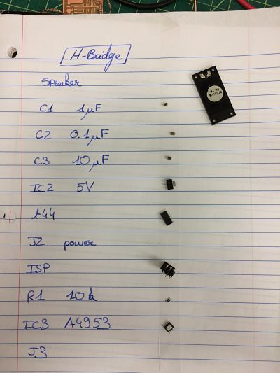
I wanted to make sure that I could do both, so I milled the two boards. And stuffed them. The issue was to understand what MOSFET to use. It was not clearly stated in the boards, so I assumed it was the N-Mosfet 100mA and 5V, but there were a lots of different options and it was not obvious what to use, as the following picture shows (cannot really read on it).
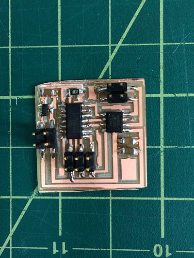
The visual results of the H-bridge board gives the following picture. We see that the traces are very deep. The modela had some issues of offsets in the z axis and thus we had to mill deeper.
The next step was to get familiar with the actual hardware. I found a speaker in my lab and I borrowed one from the architecture shop. Here are the size of the two:
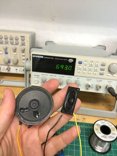
The speaker are modulated with alternative current. We make the speaker at some frequency and it creates the sound at that frequency. For example, a A is at a frequency of 440 Hz. I played a little with the speaker using different frequencies and different signal shape (sinusoidal, gates, triangle):
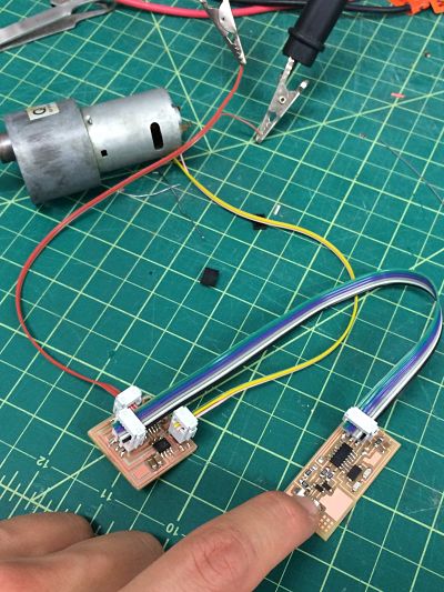
The next steps were then: the connection between hardware and board, the upload of the program (speaker and H-bridge). On my way, I also tried with a DC motor if it would work:
Unfortunately for me, it is now starting to be more complex. First, the connection of the external batteries to the board were leading to an issue: the voltage drop between the middle pin of the MOSFET and the lower was 0.5V, and when the external batteries were plugged into the board, they started to overheat and smoke was produced. I thus unplugged them immediately. Without powering the board, I could not neither program it, unfortunately. I thus want to troubleshoot that issue that could be seen with the two types of board. I suspect that it is becaue of a bad choice of MOSFET.
Some troubleshooting later, I realized what were my mistakes:
- The issue was that on the picture of the board, I could not really figure out what was the "IC2 5V" component. But then, once I knew it was a voltage regulator, I went to the fablab inventory and looked for regulators. I had the choice between different regulators but I wanted a 5V one and then I had the choice between two different packages : "SOT23-" and "SOT223-3", by looking at the picture I could then figure out wich one I needed. Similarly for the N MOSFET for the speaker board
- When I was plugging the batteries in, I was using the 4 pins, whil I actually just want to use two, because it was also one reason why I was short-circuiting the batteries.
I could thend successfully upload the code. To do so, I need:
- Download in one folder the C file and the make file
- The make file is calling the C file to make the ".hex" file that will be uploaded to the board. I can run the make file in the terminal to actually create the hex file and upload it in the board, or I can use the Arduino interface
- When I use the terminal, I use GCC, so I will start my instruction by "make" (like when I use Git, I start my instructions by "git")
- I then use "-f" to notify the file I am using next
- I then use the file name
- Then space and what I am doing explictely in the file name. By looking at the make file I can see that if I use the AVR ISP or the fabISP I have different instructions
- The code should be uploaded. One thing to be careful about is to power the board but not necessary to put the motor/speaker before the board is programmed because we don't know what can happen
An example of the code I ran would thus be:
make -f hello.speaker.45.make program-usbtiny
And that worked !!! I was really so ecited when both the speaker board and the motor worked:
But the goal was not met yet. I needed to design my ownboard to actually meet the goal. The orginal idea was to actually use the H-bridge board with the speaker. Ideally, I would record myself and then upload the message in the board and maybe if I press a buton then I can play the message. I thus need to go back to Eagle to make the schematics, then the layout, mill the board, stuff it and especially program it.
It is now time to make my own board. I wanted to add a button. I also added a LED to train managing different output. I replicated the work we did for the Embedded Programming week. The Eagle file is as follows:
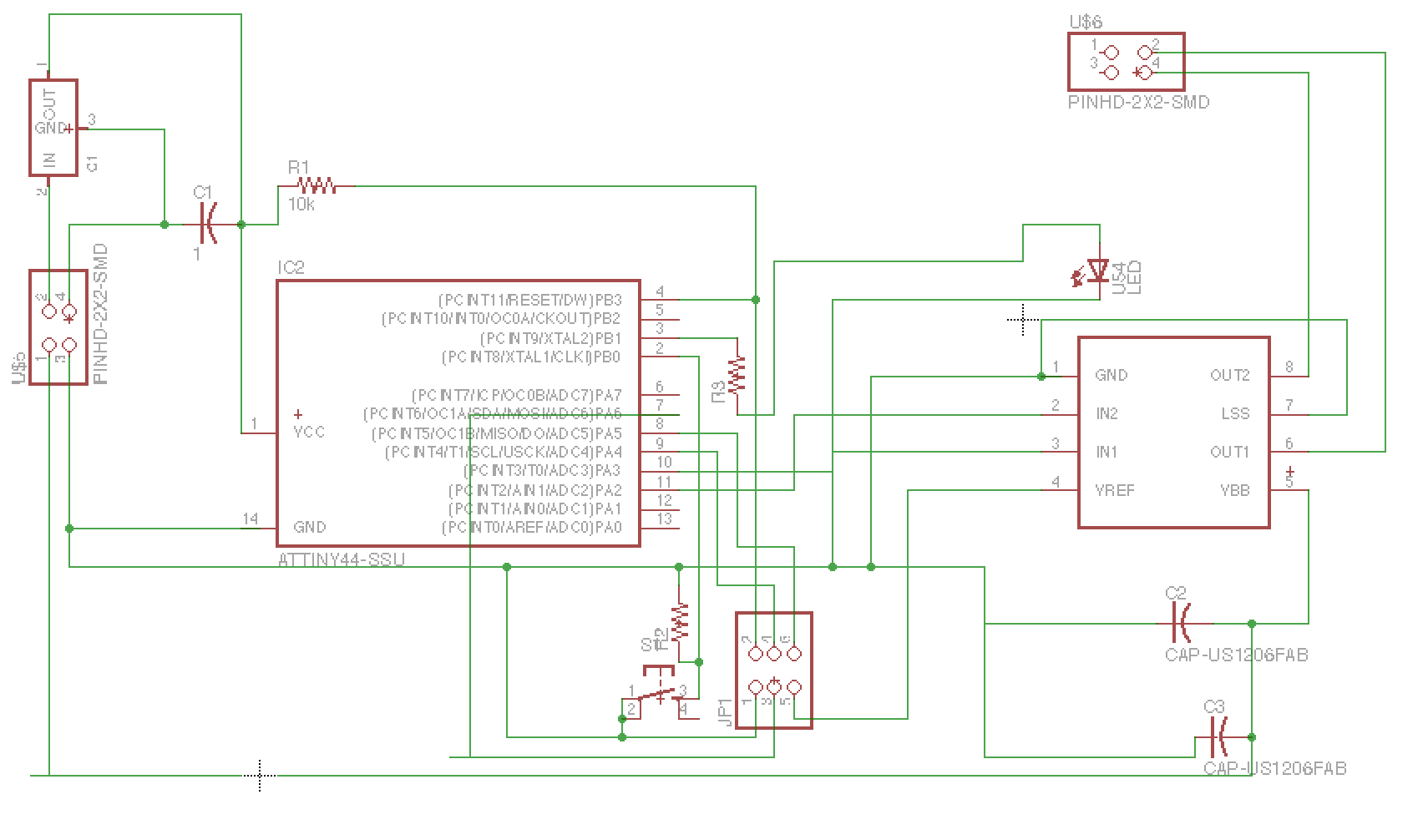
And thus the traces are as follows:
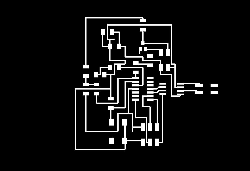
But it is here that I ran into some issues. The Modela + Fab Module had weird setup in terms of resolution and even though I exported the Eagle file with a resolution of 600 and milled it with the same resolution, the size of the file was actually too small. The traces could not fit the components. The following picture shows the ATtiny 44 next to its traces.
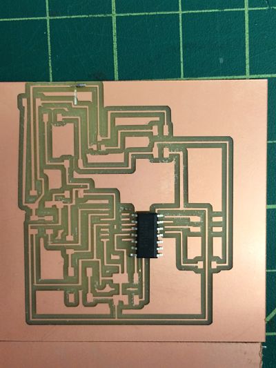
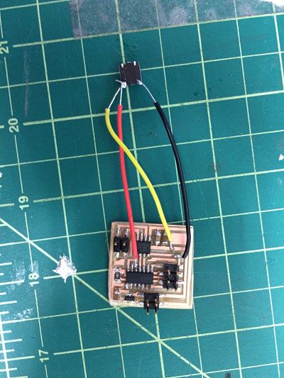
I tried several settings but I could not trouble shoot the issue. Then I noticed that the Modela was actually also capricious for a board like the FabISP, so I decided to design my own board in another way. I basically implemented the button but just by sodering extra wires:
The next step was then to figure out how to record myself and implement the file in the board. First issue: the memory on a ATtiny 44 is 4kb. So, it was a little difficult to record myself in 4kb only. So I realized I could just try to play with notes, The first step was to look at the existing code and try to figure out what it meant. The following shows the C code that is called by the make file.
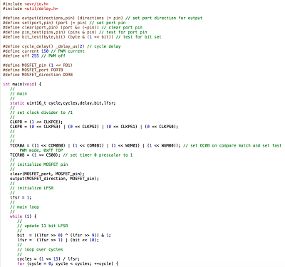
The beginning is used to define the different routines of the code. For example, when we will want to set a pin to a given value, we will use the routine "set (port,pin)". We were doing something equivalent with the Arduino interface, but with some level higher. It is good to see a lower level code. The main loop is setting the clock, and the actual code is in the while loop. As it is, "while(1)" means that the loop will keep playing indefinitely. When we look inside we see the function lsfr. It stands for Linear Feedback Shift Register and is actually an interesting function that is well described here. It is with this function that the different notes are played. I could for example, add the function of the button that the music will play only when I press the button. But actually Arduino has a good function (that I can use using ISP AVR or an ARduino or a Fabrduino (Mega 328) but not the FabISP) to play different tones here . I explored those different options
, but actually ended up playing with the motor board and code.
At the beginning, I attempted to modify the code like that:
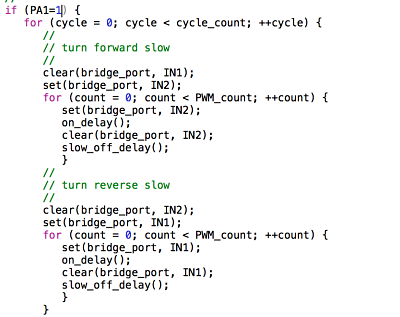
But it did not work because I had to call the routine "pin_test":
while (1) {
if (!pin_test(PINB, IN3))
And defining the pin at the beginning:
#define IN3 (1 << PA1) // IN3
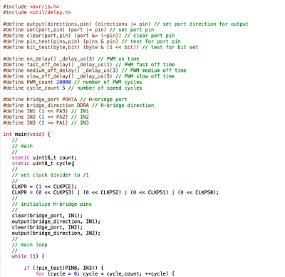
Finally, I could thus have my own board working and I could control the motor:
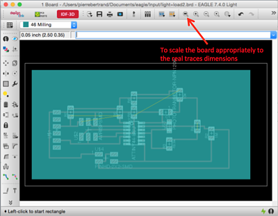
One week later, I realised why the prints were not to scale: in Eagle, I needed to press the following button: