Week 4 - Computer-Controlled Machining
Task: make something big
Go Cofee Table
Over the summer I started playing the game Go, also known as Weiqi, Igo, and Baduk. Nice full-size go boards start around $80. Instead, I decided to make a coffee table for my room and integrate my hobby with drawers for storing stones and (eventually) an integrated timing clock system for games.
Design
Originally I really wanted to make a wooden monocycle, but no matter how hard I tried I wasn't able to fit all the pieces on the two 4'x8' plywood sheets I had. Eventually I decided to go with a simple coffee table to decorate my room. To spruce things up, I wanted to lasercut some cool designs onto the side legs. I ended up choosing 4 designs: the crease pattern for the crane, the crease pattern for a simple square-twist tesselation, the projection of the hypercube to 2D, and lastly the Borromean rings -- a set of 3 rings in which removing any one of them leaves the other two unlinked, but all together the three are linked.
CADing Model
Using Rhino as usual, I designed the coffee table. Here's it in 3D:

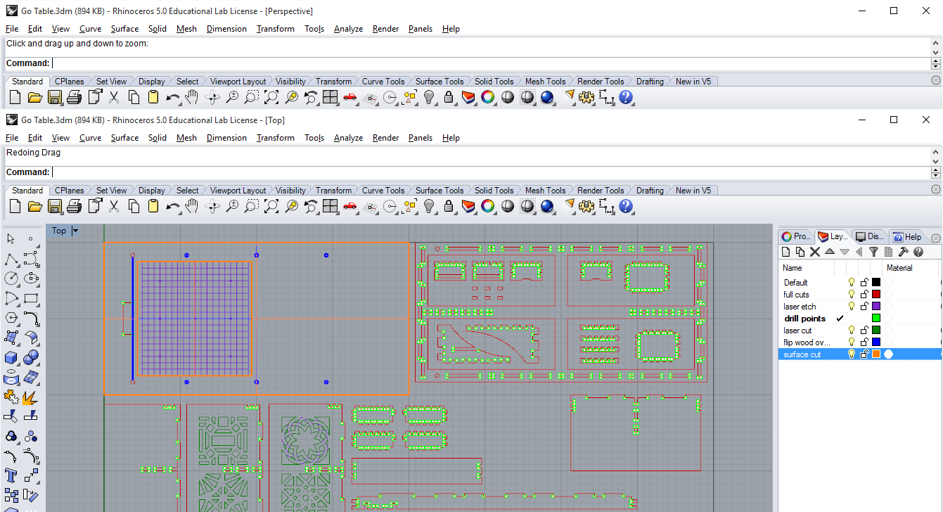
and the pieces laid out:

Getting to this point wasn't completely straight-forward however, first I had the pieces laid out on two sheets of plywood, but to save wood and time I changed it so they all fit on one. In doing so, I reduced the dimensions of the table in both length and height (I originally wanted a 2'x5'x1.5' table, but the final designn is 2'x4'x1') and added support structures under the table. I also consulted Ines, who reminded me of the capabilities of CNC to make press-fit pieces, instead of relying on screws to keep it all together. I also originally wanted to have the go board directly cut into the table-top, but realized the Onsrud's smallest bit is 1/8", which wouldn't be up to official Go board regulations which has lines of 1/32". Unfortunately, since the laser beds are only 2'x3', I decided instead to make a pocket for a separately laser-cut go board to go.
From CAD to Mastercam
I had a lot of trouble at this step, mainly due to some of the small pieces and some steps I didn't learn about until later. I made 4 different toolpaths, one for most of the cuts, one for surface milling the go board pocket, one for drilling the inner corners (you should make points on your CAD model at these spots if you're doing press-fit, since it ensures that the cut out joints will be able to lie flush against each other), and a final finishing cut to remove the onion skinn under the pieces. Out of concern for the smaller pieces getting caught up in the vacuum, I manually removed them from the final cut--which later turned out to be a decision I regretted.
Cutting on the Onsrud!
Here it goes! *no idea why the video is upside down; it's in the correct orientation on the repo...
Late night cutting the in N51

Assembly
I didn't realize how thick the onion skin was, so without the final cut all the inner cuts were completely stuck inside. To remove I went through each one with a drill and file, but I probably should've just done the final cut on these inner cuts (they were parts that any small pieces were already milled away, so removing the toolpath didn't have any benefit, though I would still remove the toolpath for the pieces that weren't inner cuts). For the remaing attached pieces, I used the bansaw to remove them. I also realized that one of my pieces wasn't modelled correctly and isn't going to fit :(. I cut off part of the joint with the bansaw and tried to wood-glue new teeth in. After a really long couple days, I've decided to save the laser cut side designs for a later day and thus final assembly (by order of operations I need those sides to be complete in order to start assembling).
Where to go from Here
I still need to finish cutting and assembling, but am excited for the final project. In the future I'd like to try more complicated surface mills and perhaps try using the shopbot instead.