Embedded Programming
And so we entered a portion of the course that I was most exctied for, as it was an area in which I had the least prior experience. I had used an arduino before, but had no experience in C, and quickly found I had no idea where to start.
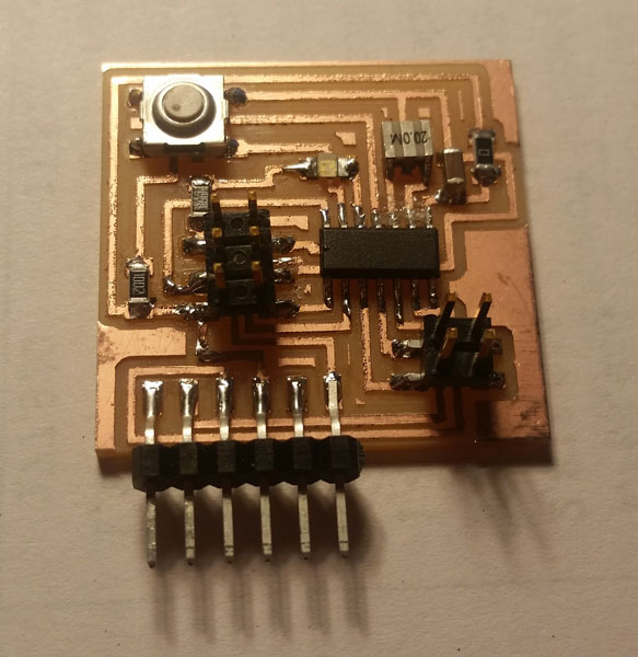
As a refersher, I have included an image of the board that had been designed earlier. The objective of this week's excercise was to modify some existing code to include the recently added button and LED, and if time allowed build a new board with additional funcitonalities.
I wanted to do as much of the programming as possible on my computer, nominally including writing to the board via the USBtiny that had been made earlier in the class, but I preceeded to run into a toolchain error of some sort that (though both devices were visible in to the machine) claimed that the USBtiny was uncreachable. I have yet to remedy this issue, and trying to do so ended up expending a good amount of time.
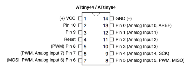
Eventually giving up on this, I reimersed myself in the arduino environment, which seemed the best place to start. I used the sample code to generate a simple blinking of the LED. A momement of confusion of occured when it turned out that the physical pinout was different from the arduino call-pins. This was corrected, and the blue LED blinked quite happily.
/*
  Blink
  Turns on an LED on for one second, then off for one second, repeatedly.

  Most Arduinos have an on-board LED you can control. On the Uno and
  Leonardo, it is attached to digital pin 13. If you're unsure what
  pin the on-board LED is connected to on your Arduino model, check
  the documentation at http://www.arduino.cc

  This example code is in the public domain.

  modified 8 May 2014
  by Scott Fitzgerald
 */


// the setup function runs once when you press reset or power the board
void setup() {
  // initialize digital pin 13 as an output.
  pinMode(8, OUTPUT);
}

// the loop function runs over and over again forever
void loop() {
  digitalWrite(8, HIGH);   // turn the LED on (HIGH is the voltage level)
  delay(1000);              // wait for a second
  digitalWrite(8, LOW);    // turn the LED off by making the voltage LOW
  delay(1000);              // wait for a second
}
A long term project I have become interested in is the fabrication of a digital watch using seven segment displays. Time keeping of some sort is therefore a feature I'd like to explore. I modified the blink code to flash once after 10 seconds, twice after 20 seconds, etc. It wasn't the best code as it used incremental rather than absolute timekeeping, but was reasonably accurate.
/*
  Timing

  this code is intended to progressivly sum blinks every 10 seconds
  to keep track of time.
 */

int count = 0;
int pulse = 0;
int remainder = 10000;

// the setup function runs once when you press reset or power the board
void setup() {
  // initialize digital pin 13 as an output.
  pinMode(8, OUTPUT);
}

// the loop function runs over and over again forever
void loop() {
  delay(remainder);
  pulse = count + 1;
  count = pulse;
  remainder = 10000;

  while (pulse>0)
  {
    digitalWrite(8, HIGH);   // turn the LED on (HIGH is the voltage level)
    delay(250);              // wait for a second
    digitalWrite(8, LOW);    // turn the LED off by making the voltage LOW
    delay(250);              // wait for a second

    pulse = pulse -1;

  }
  remainder = remainder - count*500;
}
Next I added in the button, giving it a reset feature. Pressing the button would cause the count to start again at zero.
    /*
  Timing with press-button reset

  this code is intended to progressivly sum blinks every 10 seconds
  to keep track of time. pressing the button will zero the sysetm
 */
# define LED 8
# define BUTTON 7

int count = 0;
int pulse = 0;
int remainder = 10000;

// the setup function runs once when you press reset or power the board
void setup() {
  // initialize digital pin 13 as an output.
  pinMode(LED, OUTPUT);
  pinMode(BUTTON, INPUT);
  digitalWrite(BUTTON, HIGH);
}

// the loop function runs over and over again forever
void loop() {
  if (digitalRead(BUTTON) == HIGH)
  {
    delay(remainder);
    pulse = count + 1;
    count = pulse;
    remainder = 10000;

    while (pulse>0)
    {
      digitalWrite(LED, HIGH);   // turn the LED on (HIGH is the voltage level)
      delay(250);              // wait for a second
      digitalWrite(LED, LOW);    // turn the LED off by making the voltage LOW
      delay(250);              // wait for a second

      pulse = pulse -1;

    }
    remainder = remainder - count*500;
  }
  else
  {
    pulse = 0;
    count = 0;
  }
}
The last experiment was made in time setting. The duration of the button press would be recorded, and this would be used to determine the length that the led would be pulsed. This was an important feature in my future digital watch as a press and hold of the set buttons will put it into a "set" mode.
    /*
  Duration of button press would set timing of button flash.
*/
#define LED 8
#define BUTTON 7

int count = 0;
int pulse = 0;
int remainder = 10000;
int hold = 250;
int start_time = 0;
int first_press = 1;

// the setup function runs once when you press reset or power the board
void setup() {
  // initialize digital pin 13 as an output.
  pinMode(LED, OUTPUT);
  pinMode(BUTTON, INPUT);
  digitalWrite(BUTTON, HIGH);
}

// the loop function runs over and over again forever
void loop() {
  if (digitalRead(BUTTON) == HIGH)
  {
    first_press = 1;
    digitalWrite(LED, HIGH);   // turn the LED on (HIGH is the voltage level)
    delay(hold);              // wait for a second
    digitalWrite(LED, LOW);    // turn the LED off by making the voltage LOW
    delay(hold);              // wait for a sec
  }
  else
  {
    if(first_press == 1)
    {
      start_time = millis();
      first_press =0;
    }
    hold = millis() - start_time;

  }
}
Reasonably satisfied with a rudimentary understanding of how to use the board, next steps will be in eagle as I redesign a the board to multiplex some seven segment displays.