5. Electronics Design
Hello World!
Eagle
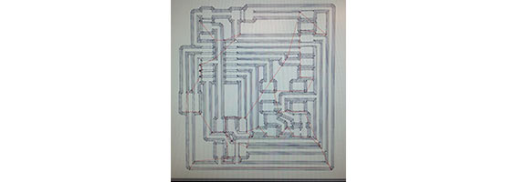
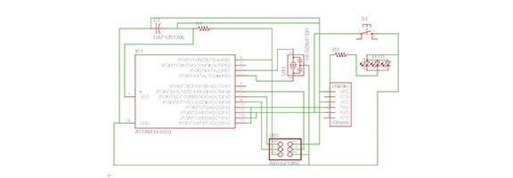
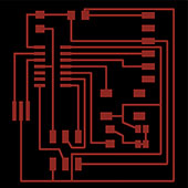 I started out by copying over all of the components from the example board into Eagle. This step was pretty self explanatory, I just followed a few of the tips from previous class pages and tutorials. Staying in the schematic page, I next connected all of the wires to the correct leads from the example board as neat as I could without putting too much into it. I figured the cleanliness of the schematic for something this small wasn't that important, it's the board that matters. Then I added in the LED and button switch to individual pins on the ATTiny44. Each one just had to come down from the pin to ground, and the LED had a resitor in series as well to limit the current through the diode. Organizing the board was more difficult. I had to figure out how to run all of the leads to not intersect, and to fit into all the right gaps. On that note, I learned pretty late in the game that holding 'alt' while moving components switches over to a finer grid pattern than normal. This would've saved me time trying to coordinate and fit everything in place, and is part of the reason the right side of my board is so busy. The schematic and board diagram are both attached below as examples.

Manufacturing
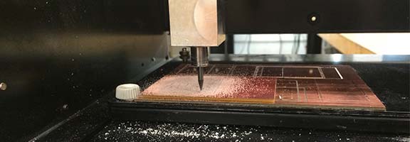
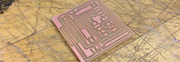
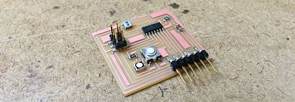
I exported the board from Eagle by layer (be sure to click monochrome!) to get the necessary trace and outline patterns for the mill. Once these were saved as .png's the process was the exact same as week two. I got the mill setup and loaded the 1/64" bit for the traces, followed by the 1/32" for the outline. Once it was cut, I gathered all of the components and soldered them onto the board. I'll have to hook it up and test it to be sure it's ready for programming in a few weeks!