8. Output Devices
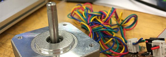
A bipolar stepper motor to drive my split flap display
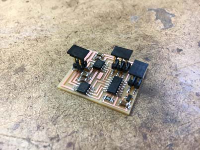
Practice Board
I began by simply manufacturing the bipolar stepper board from Neil's example. I had some trouble with machining the board, as a lot of people in the architecture section seem to have. When I went to cut the traces the passes weren't cutting deep enough, so I had to reload the bit and trace them out again. I'm not entirely sure, but I think the set screw might have slipped slightly when I was loading the bit the first time (my mistake). After the second pass everything worked out fine!


The next step was obviously to stuff the board. I've gotten pretty good at soldering at this point and was able to crank out the board in under half an hour! (After locating all of the components that is). I forgot to take pictures of this process, so I'll be sure to inlcude those in the next update with the board I design for the motors. Basically, I like to lay some solder onto the pad, then line up the component with tweezers and hold it in place by pressing down on top of it. Then I reflow the solder by applying heat to the pad and leg of the component with the soldering iron. This is the method that Neil taught us in class, and it seems to work really well, even for the tiniest of components (as long as the leads extend from the part).

I ran into all kinds of issues trying to program the board. I had to flip through a lot of the class pages to be sure that I was hooking up the 9v battery correctly, once I realized that this was in fact how I needed to power the board. Then my board immediately failed the smoke test. It turned out that I had the battery cable plugged in in the wrong direction, so I switched that around and tried again. The board was no longer smoking, but the battery got pretty hot pretty fast. I couldn't program the board without power running to it, and on top of that, my computer was failing to program any board. Up until this point I had been just using the computer in the Arch Shop and the AVRISP to program the boards, but I decided I would like to be able to work at home leading up to the amount of time I was sure the final project would take (more on this in embedded programming). I went to office hours the next day, and quickly realized in conversation that my board had a major and obvious flaw. I had used a MOSFET where the 5V Regulator should go due to their similar footprints and my complete lack of any kind of electronics knowledge. After switching these components I was finally ready to program the board.
Unfortunately, I was still having some programming issues once I got this figured out. I was (and sort of am) still very confused when it comes to the issue of programming, and in following the directions I failed to erase the -fuses line from the code required to load the program. Once this was pointed out to me though, I was able to get the board working immediately!