9. Input Devices
A synchronous detection LED device.
Practice Board
I had falled behind quite a bit leading into this week, so this was the first week that I was actually able to program a board to work. Becuase of this, I decided to start with one of Neil's examples, and then develop the board from there. I had wanted to use one of the motion sensors, but I wasn't able to find one in the Arch Shop, and I didn't want to waste one of the input boards since I figured a lot of people would like to use them for their final projects, I so went for a light input board instead.
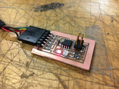
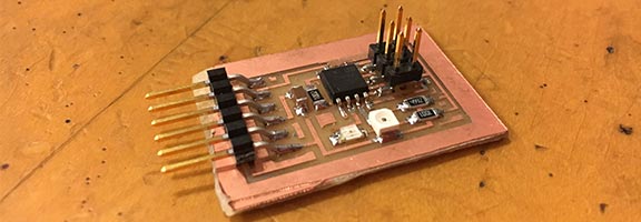
I began by manufacturing the example synchronous detection board from Neil's example. I cut the board during the peak of the Arch Shop's Modela toubles. I was able to get the traces machined fine, but then when I tried to cut out the outline the bit drove right across the board and gouged into the traces. On the second run I decided not to risk the outline cut, so I put the traces as close to the corner of the board as I could, then cut the other two sides out by hand by scoring and breaking the board (which explains the gross edge in the image).
Stuffing the board was easy as well, as I said before, I've gotten pretty good at this! there weren't any particularly challenging components either outside of the phototransistor.
Loading the program was faily easy as well! I used the computer in the Arch Shop and the AVRISP2. I just downloaded the c and make files from the inputs week's page into a file on the desktop and followed Neil's example in order to write the program to the board. This was the first board that I was actually able to get working as desired! I have been struggling to get the linked python script to run though...
I'm planning on coming back to this unit in order to create my own inputs board based on what I leared with this example.