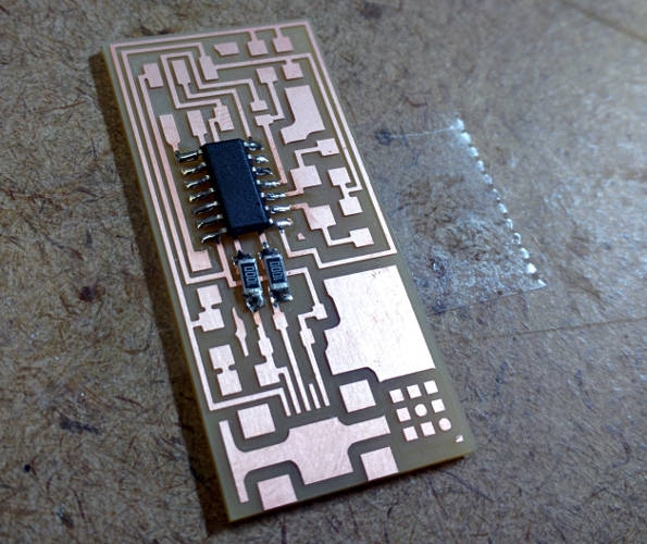
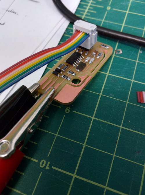
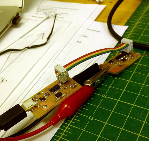
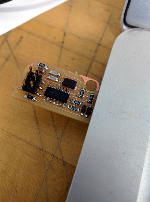
The purpose of this weeks assignment was to learn to rapidly prototype circuit boards. This was a two step-process. First we would mill the circuit boards using a modela and then stuff the circuit boards ourselves. Despite having a degree in Computer Engineering (that I have never used...) I never got to produce my own PCB or solder surface mount components, so I was excited to give it a try.
The board that we were given to build was an fabISP, or in-system programmer. This would allow us to later program other AVR micro-controllers that we will be designing as the course moves forward. The board schematics and variations can be found on the MAS.836 electronics production page.
The first board I planned on building was the hello.44.isp.cad board for which the schematic, traces, and outline are all available on the class website.
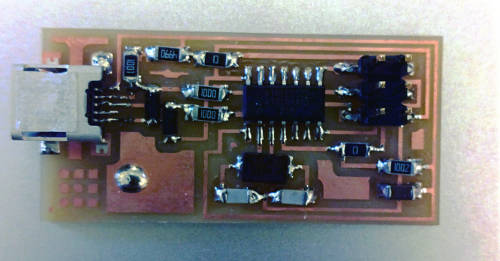
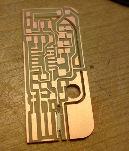
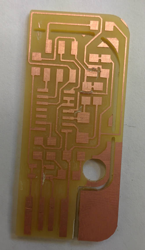
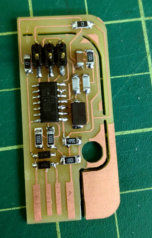
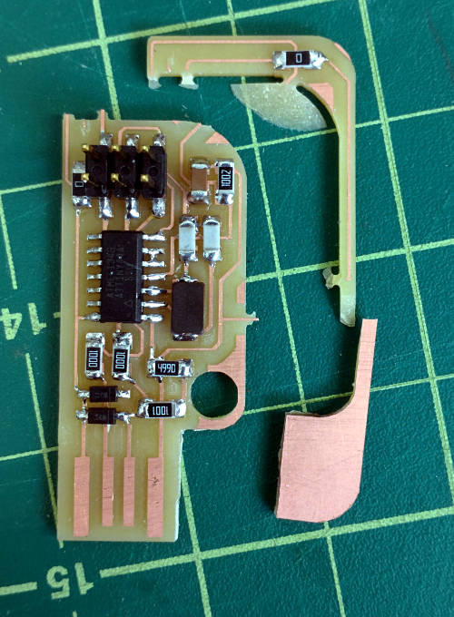
I wanted to build a second board so that I could test the functionality of my first fabISP and I was also really interested in making the breakaway circuit board that Valentin had make in a previous year.
When looking for the parts for the second board I realized that Valentin's schematic called for two 18pF capacitors that were not located in the standard fabLab inventory. This seemed strange, given that the circuit was nominally a re-laid out version of what I had already built. To double check this I decided to draw out the section of the circuit that included these parts for both circuits

Looking at the parallel diagrams, it is apparent that the portion of the circuit containing the 20MHz oscillator simply has 3 different capacitors between the two designs. Given that my first fabISP worked, and this design should be the same, it stands to reason that I should be able to replace the two 18pF capacitors and .1uF capacitor with the 10pF and 1uF capacitors I used in my first circuit. The math must work out that these components result in the same outcome, or perhaps his design is calling for a different oscillator than we are now using.
This board was somewhat difficult to mill properly. Given that we are using the milled traces as the USB connection it is important to ensure enough of the surplus copper is milled away that you won't have spurious connections. To do this I used a number of offsets value of 6 instead of 4. The second issue was that the cutout contains some curves, and the board had a habit of moving before it was completely milled.
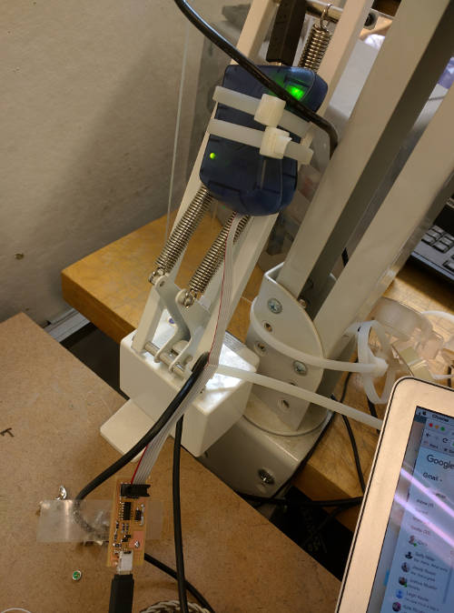
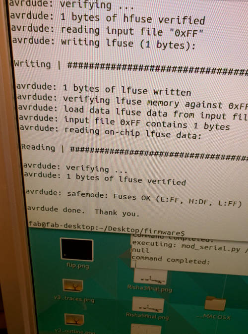
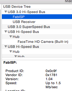
I wanted to program the board from my personal computer using the fabISP I had built, so I followed the instructions here to set up the proper software and toolchain for AVR Programming.
After setting up the toolchain and downloading the firmware, I had to edit the makefile to use the usbtiny configuration which should work with the fabISP.
# Proper Makefile Config
AVRDUDE = avrdude -c usbtiny -p $(DEVICE) # fabISP
#AVRDUDE = avrdude -c avrisp2 -P usb -p $(DEVICE) # commercial pgmr


