Push towards the Final Project
Output devices is where my odyssey with my final project began. I was toying around with a number ideas (remember the trash can?). But I have settled on creating a chess board that automates blitz chess. final project is probably going to involve some sort of LCD, so I decided to make the LCD project as a soft introduction to getting one to work. I didn’t make any modifications to the plans that can be found on the fabclasses website.
Lets step back a minute.
The rules of blitz chess are a bit more complicated than regular chess. For example, if you make an illegal move and your opponent does not catch it before they move, its ayokay. If you forget to click your clock, your opponent is under no obligation to remind you to click your clock and your precious time will slip away. The design that I want to implement will provide two improvements: First, it will prevent people forgetting about their timer. Second, it will shave precious seconds off of the amount of time it takes to switch clocks.
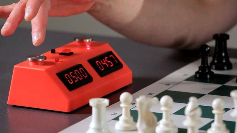
Blitz Chess
The rules of blitz chess are a bit more complicated than regular chess. For example, if you make an illegal move and your opponent does not catch it before they move, its ayokay. If you forget to click your clock, your opponent is under no obligation to remind you to click your clock and your precious time will slip away. The design that I want to implement will provide two improvements: First, it will prevent people forgetting about their timer. Second, it will shave precious seconds off of the amount of time it takes to switch clocks.
General Ideation
The general idea I have in mind is to have a blitz chess board with two LCDs that switches clocks when a piece is put down. After much thought, the state of going from 0 (no piece) to 1 (piece) is the demarcation of the change of turn. So, the specification is pretty simple. Have a set of LCDs keeping track of a set amount of time, figure out a sensor that can tell when a square on the board is occupied or not occupied and switch the timers when one of these squares goes from not having a piece to having one.
Ok, lets get started.
Output Devices
My goal for this week is to build a normal chess timer out of a fabduino and two LCDs. To preempt some further discussion. I decided to build all of the electronics for my output devices out of Arduino type chips. I decided that I needed the higher level of abstraction provided by the libraries if I was going to complete anything worthwhile. C was just too much of a barrier.
Building the Fabduino
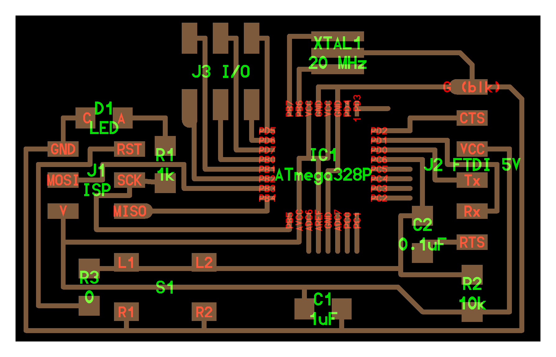
There are various designs that are available to the would be Arduino maker. The first one I built is the Fabkit, which is the first hit on google when you google fabduino.
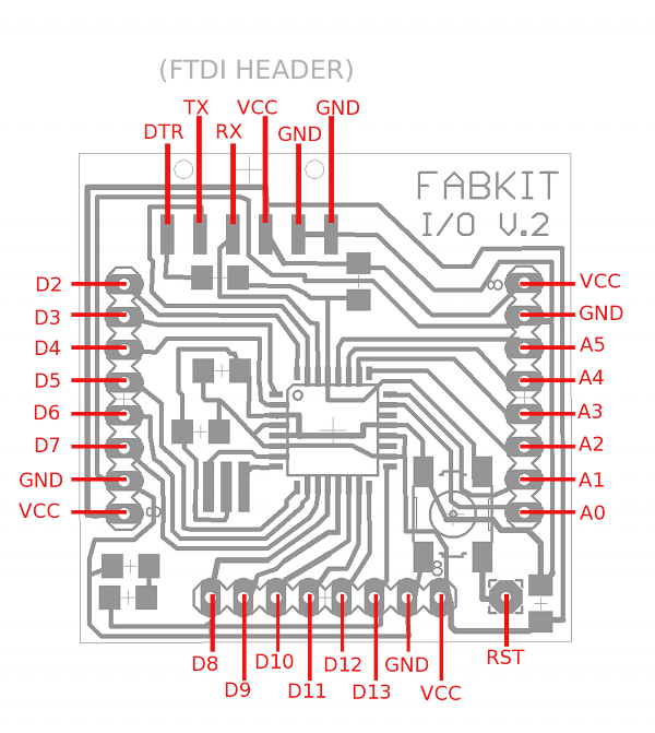
Fabkit
But there are plenty of other options. Neils kit. Dan Chens.
The things you should look for when selecting a design (or designing one) are the number of pins you need and other peripherals. Dans kit is good for doing motor control (which was not of interest to me). After I built the first fabkit, I went on to build three others. Two of which ran into a major issue that I will detail in output devices.
Hooking Up the LCDs
I started with just getting one up and running. Heres some quick tips on LCDs:
1) You will end up hooking 10 pins on the LCD itself in a minimal setup. Only six of them require data (they only occupy six precious pins on an Arduino).
2) Pins 1-6 provide, respectively, ground, VCC, a mediating voltage that regulates the backlight, Register select (basically what are you writing to), read or write (this is grounded in my design because I am only writing), and a curiously named enable (I would be lying to tell you I knew).
3) Pins 10-14 (in the 4 bit configuration) are the pins that actually write what you’re going to say to the LCD.
After too much time figuring that stuff out I managed to put together the one-LCD permutation of this board. I tested the board with code here.
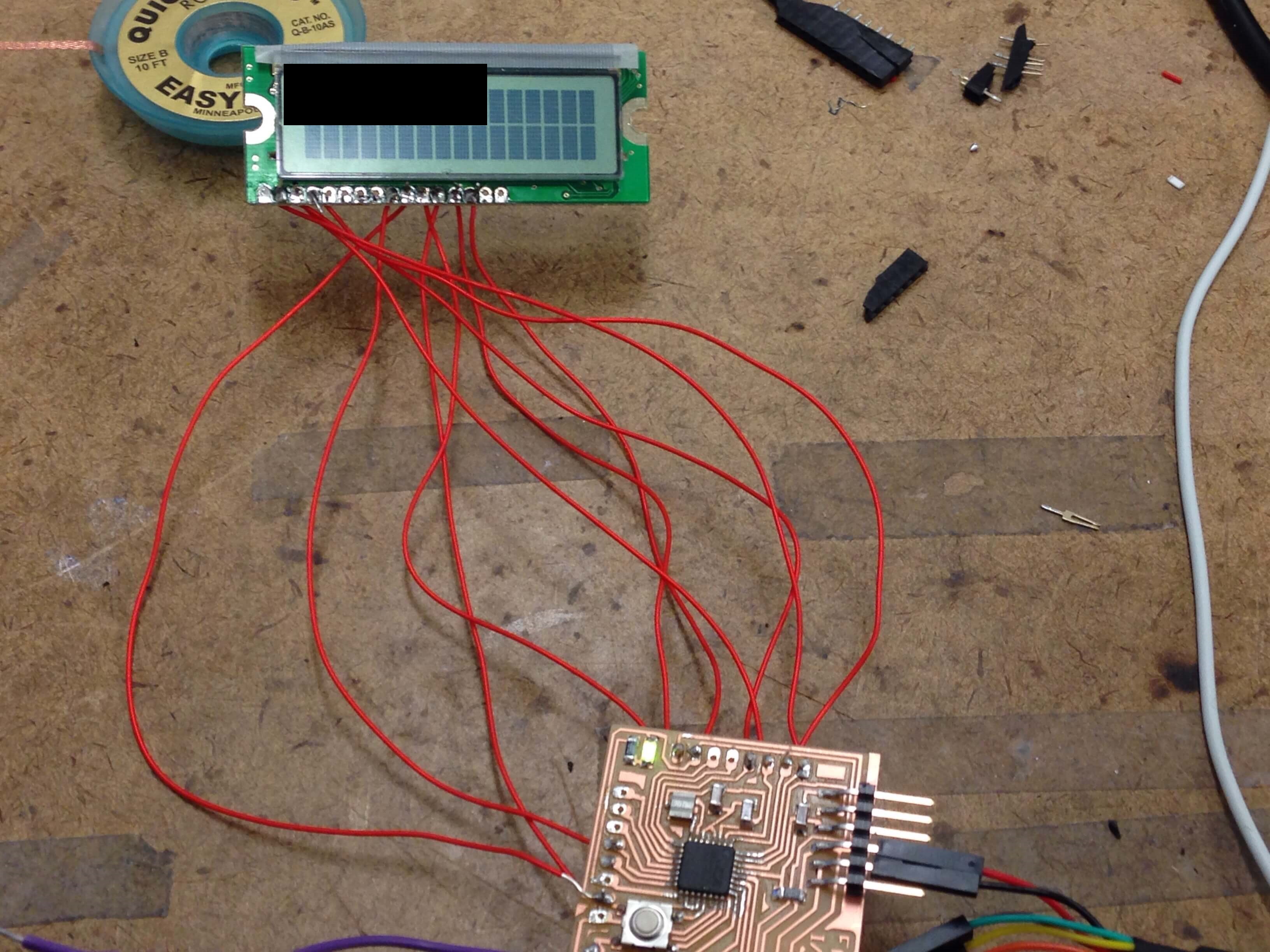
I edited the picture because I printed an explative
Here is the code I used to test the board.
Two LCDs
If you thought that transitioning from one LCD to two would be as simple as just hooking up another LCD, you would have thought as I did and we both were wrong. The reality is not that simple. It turns out that the two LCDs can share many of the same pins (with the exception of the mysterious enable pin). This page was really helpful.
After reading through that and re-soldering the board. I got the two working together.
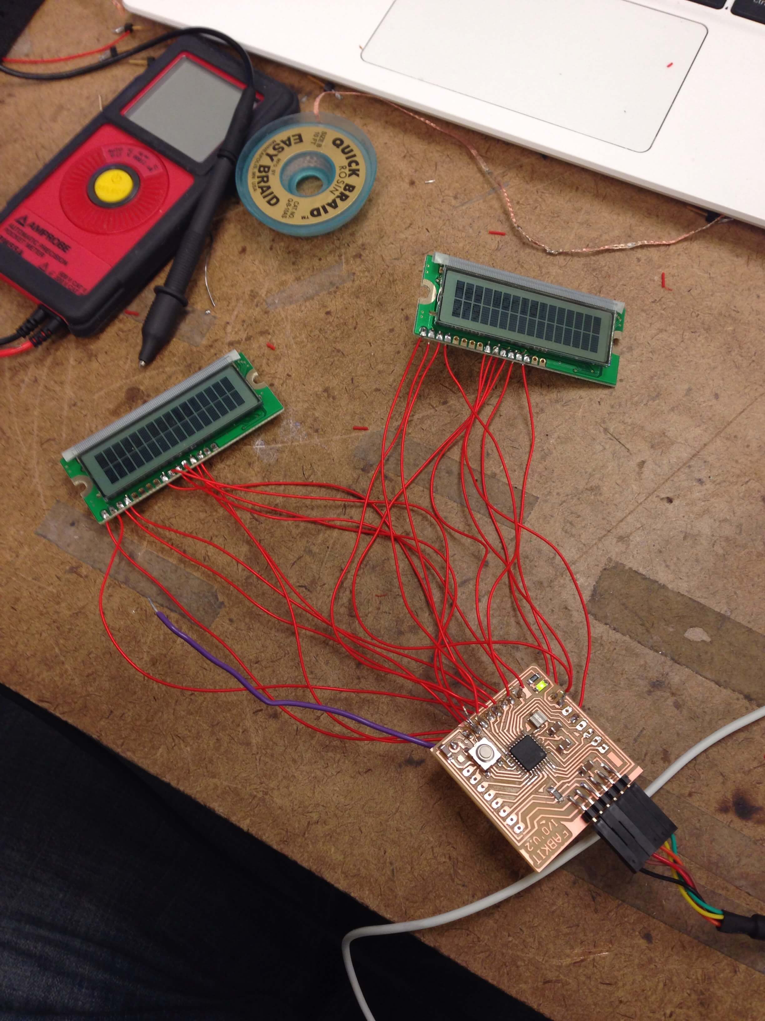
Two LCDs
Code
Now that I had the two LCDs working all that was left was code implementation. I ruthlessly stole the code found here and modified it for two screens. After uploading the code everything worked beautifully.