Output Devices with Atmega328p
Using Atmega328p
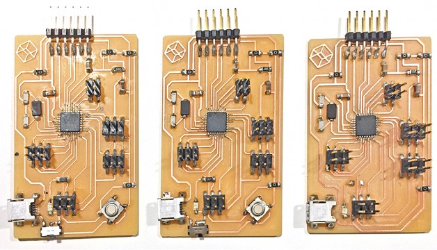
I would like to make 2 servos with 2 degree of freedom that moves up and down and side to side based on the finger gestures. I require more pins than the Attiny 44. I decided to go with Atmega328p and make my own version of Arduino ( same as Arduino pro mini board).
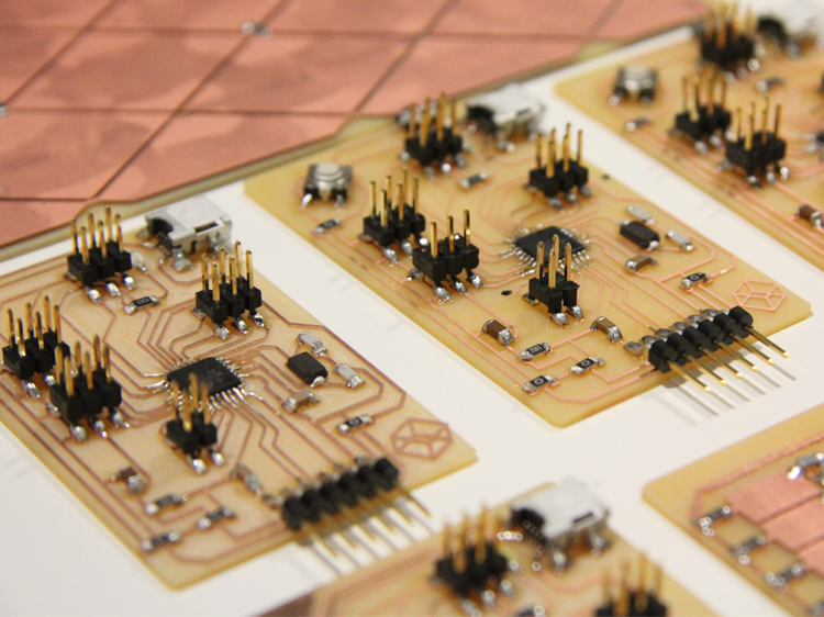
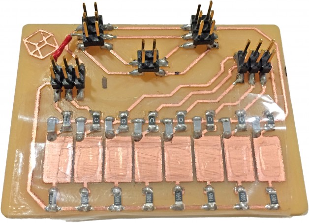
It took me a few trials to get the basic board running, but once it’s working I added the reset button, the USB external power jack (unregulated) and I added several servo pins.
I limited my self to design the board under 4″ by 2″, I also broke out several Analog and Digital pins.
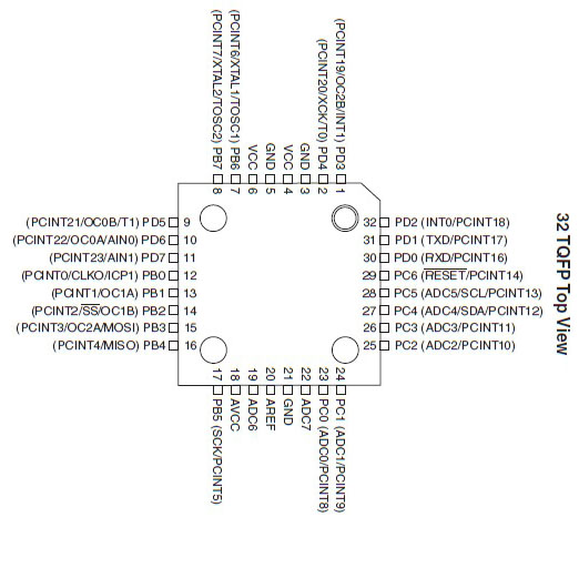
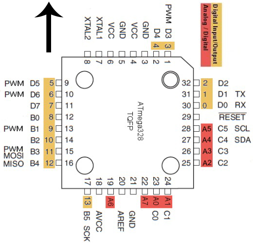
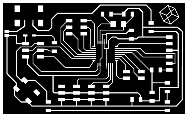
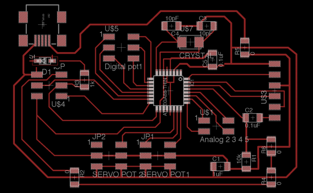
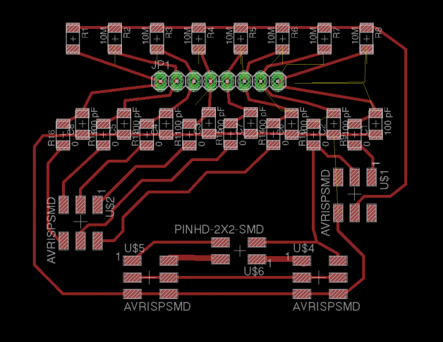
I used the following charts to help me map out the board.
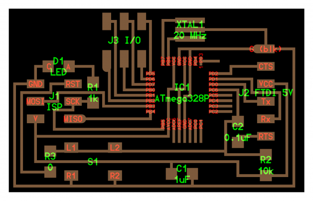
Tip: To make the milling and stuffing easier you will want to make the pads that only comes from inside of the IC longer, extend the out a bit more. Also deleting the unused pin traces also helps with the stuffing. (The IC has enough pins to hold itself in place)
Example: I deleted the unused USB data pins, only leave the GND and VCC
Tips for getting Arduino IDE working on your own board
#1. Here are the json URLs for all Mega & Attiny board with all sorts of processor speed (1, 8, 16, 20 mHz)
Paste The following URLs into the Additional board section. (I also included other Atmega board like 382p)

#2. Burn Boot Loader using your FabISP from previous class or AVR MII
#3. Done!
All you need to program now is the FTDI cable, you can also use ISP pins to do all your programing and take out the FTDI cable all together (you might want to break out the TX/RX if yo wanna do serial communication)
My Input Devices
I used Capacitive Sensing Library by Paul Badger
I map each receiving pins to a position for the servo.
Here is what the board looks like. With the header pins I can reused the “DanDurino” for many other projects. Download Eagle File
#include #include Servo myservo; // create servo object to control a servo // twelve servo objects can be created on most boards int pos = 0; // variable to store the servo position /* * CapitiveSense Library Demo Sketch * Paul Badger 2008 * Uses a high value resistor e.g. 10M between send pin and receive pin * Resistor effects sensitivity, experiment with values, 50K - 50M. Larger resistor values yield larger sensor values. * Receive pin is the sensor pin - try different amounts of foil/metal on this pin */ CapacitiveSensor cs_12 = CapacitiveSensor(11,12); // 10M resistor between pins 4 & 2, pin 2 is sensor pin, add a wire and or foil if desired CapacitiveSensor cs_13 = CapacitiveSensor(11,13); // 10M resistor between pins 4 & 6, pin 6 is sensor pin, add a wire and or foil CapacitiveSensor cs_10 = CapacitiveSensor(11,10); // 10M resistor between pins 4 & 8, pin 8 is sensor pin, add a wire and or foil CapacitiveSensor cs_9 = CapacitiveSensor(11,9); // 10M resistor between pins 4 & 8, pin 8 is sensor pin, add a wire and or foil CapacitiveSensor cs_8 = CapacitiveSensor(11,8); // 10M resistor between pins 4 & 8, pin 8 is sensor pin, add a wire and or foil CapacitiveSensor cs_7 = CapacitiveSensor(11,7); // 10M resistor between pins 4 & 8, pin 8 is sensor pin, add a wire and or foil CapacitiveSensor cs_6 = CapacitiveSensor(11,6); // 10M resistor between pins 4 & 8, pin 8 is sensor pin, add a wire and or foil CapacitiveSensor cs_5 = CapacitiveSensor(11,5); // 10M resistor between pins 4 & 8, pin 8 is sensor pin, add a wire and or foil int servopos =0; int maxpos; int maxn; void setup() { //cs_12.set_CS_AutocaL_Millis(0xFFFFFFFF); // turn off autocalibrate on channel 1 - just as an example //Serial.begin(9600); myservo.attach(A3); // attaches the servo on pin 9 to the servo object } void loop() { //long start = millis(); //long debug_cs = cs_13.capacitiveSensor(5); //debug long t0 = cs_12.capacitiveSensor(5); //0 maxpos=0; maxn=t0; long t22 = cs_13.capacitiveSensor(5); //30 if (t22>maxn){maxn=t22; maxpos=22;} if (t0>1000 && t22>1000){maxn=t22; maxpos=11;} long t44 = cs_8.capacitiveSensor(5); //30 if (t44>maxn){maxn=t44; maxpos=44;} if (t22>1000 && t44>1000){maxn=t44; maxpos=33;} // in the midle long t66 = cs_9.capacitiveSensor(5); //90 if (t66>maxn){maxn=t66; maxpos=66;} if (t44>1000 && t66>1000){maxn=t66; maxpos=55;} // in the midle long t88 = cs_6.capacitiveSensor(5); // 120 if (t88>maxn){maxn=t88; maxpos=88;} if (t66>1000 && t88>1000){maxn=t88; maxpos=77;} // in the midle long t110 = cs_7.capacitiveSensor(5); // 150 if (t110>maxn){maxn=t110; maxpos=110;} if (t88>1000 && t110>1000){maxn=t88; maxpos=99;} // in the midle long t132 = cs_5.capacitiveSensor(5); //150 if (t132>maxn){maxn=t132; maxpos=132;} if (t110>1000 && t132>1000){maxn=t132; maxpos=99;} // in the midle long t154 = cs_10.capacitiveSensor(5); //180 if (t154>maxn){maxn=t154; maxpos=154;} if (t132>1000 && t154>1000){maxn=t154; maxpos=143;} // in the midle // tab character for debug windown spacing //Serial.println(debug_cs); // print sensor output 1 if (maxn>200){ myservo.write(maxpos); // tell servo to go to position in variable 'pos' } //delay(15); } |
One More Thing
Why 1 servo when you can do 2 servos…
I created this capacitive sensors in a grid but at very low resolution.
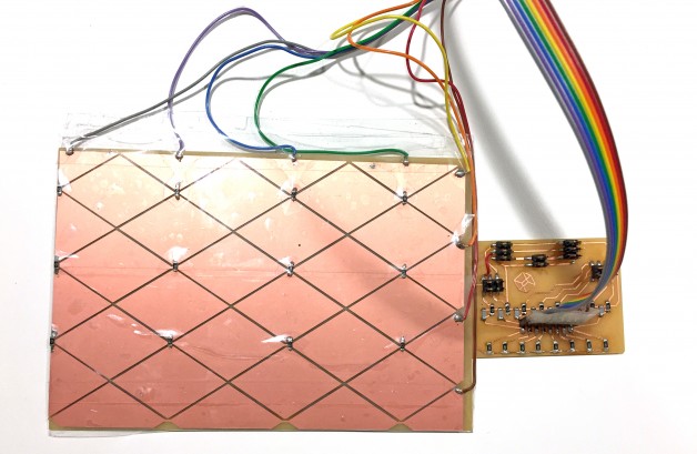
I used the sensor data to map out side to side up and down motion to the servo. The code isn’t perfect yet … but this is what I have so far, I will spend more time to fix it.
#include #include Servo myservoA; // create servo object to control a servo Servo myservoB; // create servo object to control a servo // twelve servo objects can be created on most boards int pos = 0; // variable to store the servo position int firstpos; /* * CapitiveSense Library Demo Sketch * Paul Badger 2008 * Uses a high value resistor e.g. 10M between send pin and receive pin * Resistor effects sensitivity, experiment with values, 50K - 50M. Larger resistor values yield larger sensor values. * Receive pin is the sensor pin - try different amounts of foil/metal on this pin */ // not in order CapacitiveSensor cs_12 = CapacitiveSensor(11,12); // 10M resistor between pins 4 & 2, pin 2 is sensor pin, add a wire and or foil if desired CapacitiveSensor cs_13 = CapacitiveSensor(11,16); // A2 // 10M resistor between pins 4 & 6, pin 6 is sensor pin, add a wire and or foil CapacitiveSensor cs_10 = CapacitiveSensor(11,10); // 10M resistor between pins 4 & 8, pin 8 is sensor pin, add a wire and or foil CapacitiveSensor cs_9 = CapacitiveSensor(11,9); // 10M resistor between pins 4 & 8, pin 8 is sensor pin, add a wire and or foil CapacitiveSensor cs_8 = CapacitiveSensor(11,8); // 10M resistor between pins 4 & 8, pin 8 is sensor pin, add a wire and or foil CapacitiveSensor cs_7 = CapacitiveSensor(11,7); // 10M resistor between pins 4 & 8, pin 8 is sensor pin, add a wire and or foil CapacitiveSensor cs_6 = CapacitiveSensor(11,6); // 10M resistor between pins 4 & 8, pin 8 is sensor pin, add a wire and or foil CapacitiveSensor cs_5 = CapacitiveSensor(11,5); // 10M resistor between pins 4 & 8, pin 8 is sensor pin, add a wire and or foil int servopos =0; int maxpos; int maxn; void setup() { //cs_12.set_CS_AutocaL_Millis(0xFFFFFFFF); // turn off autocalibrate on channel 1 - just as an example Serial.begin(9600); myservoA.attach(A0); // attaches the servo on pin 9 to the servo object myservoB.attach(A1); // attaches the servo on pin 9 to the servo object } void loop() { //long start = millis(); //long debug_cs = cs_13.capacitiveSensor(5); //debug long t0 = cs_12.capacitiveSensor(5); //0 maxpos=0; firstpos=0; maxn=t0; long t60 = cs_13.capacitiveSensor(5); //30 if (t60>maxn){maxn=t60; maxpos=60;} long t120 = cs_8.capacitiveSensor(5); //30 if (t120>maxn){maxn=t120; maxpos=120;} long t170 = cs_9.capacitiveSensor(5); //90 if (t170>maxn){maxn=t170; maxpos=170;} firstpos=maxpos; /// t0 = cs_6.capacitiveSensor(5); //0 maxpos=0; maxn=t0; t60 = cs_7.capacitiveSensor(5); //30 if (t60>maxn){maxn=t60; maxpos=60;} t120 = cs_5.capacitiveSensor(5); //30 if (t120>maxn){maxn=t120; maxpos=120;} t170 = cs_10.capacitiveSensor(5); //90 if (t170>maxn){maxn=t170; maxpos=170;} /// // tab character for debug windown spacing if (maxn>1000){ myservoA.write(firstpos); // tell servo to go to position in variable 'pos' myservoB.write(maxpos); // tell servo to go to position in variable 'pos' } /* Serial.print(cs_12.capacitiveSensor(5)); // print sensor output 1 Serial.print(" "); // print sensor output 1 Serial.print(cs_13.capacitiveSensor(5)); // print sensor output 1 Serial.print(" "); // print sensor output 1 Serial.print(cs_8.capacitiveSensor(5)); // print sensor output 1 Serial.print(" "); // print sensor output 1 Serial.println(cs_13.capacitiveSensor(30)); // print sensor output 1 */ } |
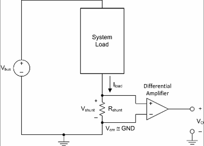
Next Step: Measuring the current
We have many options to sense current. An easy one is to use a shunt resistor (and probably an operational amplifier). Another is to use a hall effect current sensor such as the ACS711.”
(Thanks to Jean-François Duval’s help )
Let’s say we move the servo arm from 0 to 180, if the servo arm is physically stop by an obstacle (let’s say around 100 degree) and causes the current to go up and it would be nice if the Micro controller can sense this and pull back the arm. This would be important for human robot interaction.
I think I will save this part of the project for next week.