Vinyl Cutting
Surprise, surprise... Rupert is back! (But this time in a different form) I decided to make a nice laptop sticker of the iconic Rupert M. Leopold. As if anyone needed another reminder of my cat lady affliction.

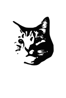
First off, I took one of my favorite pictures of Rupert and brought it into Inkscape. I used the trace bitmap function to get a black and white version of the photo. The original conversion had way too many small white details in the right side of the face, so I manually editted those out to prevent a later weeding nightmare after the vinyl was cut.
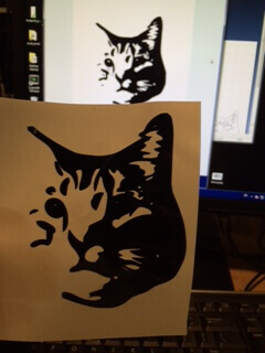

I originally tried to use FabModules, but I wasn't able to get the path settings that I wanted. The image ended up looking a little choppy. Instead I rebooted to Windows and used the vinyl cutter from there. Using the Roland vinyl cutter with a force of 140 and a speed of 20 I cut a few stickers: primarily for my laptop, but I'm sure there will be another obvious use soon (a stencil maybe?). It took a little while to get the weeding technique down, especially with some of the finer black dots on the left hand side of the design, next time I'll make those bigger or eliminate them entirely. All in all, I'm very satisfied with the final product!
Laser Cut Press Fit Kit

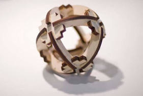
My inspiration for the press fit kit came from some examples of 3D shapes that were put together using joints and cross pieces. Above is the Atomium in Belgium as well as another press fit kit. I decided to make something similar in nature. I really liked the idea of being able to make multiple things with the same pieces, the joint and cross piece idea seemed to be a nice way of accomplishing this as well.
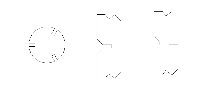
Originally, I had created two rectangles as cross pieces and triangles as the joints. I used Rhino to design the pieces and then imported the pieces to Solidworks for assembly. (Rhino doesn't really have a good way of assembling multiple pieces, but Solidworks is great for this). After assembling the pieces in Solidworks it was clear that there were overlaps of material everywhere i.e. it was not physically possible. To get rid of some of the material I made the joint into a circle, and the cross links needed material taken off in the corners and sides. The final pieces are shown above.
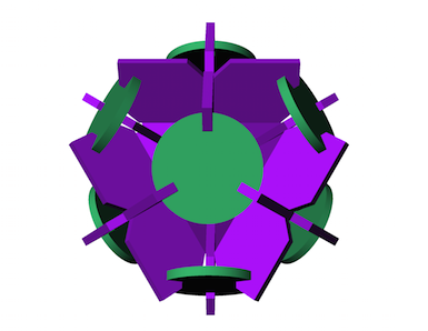
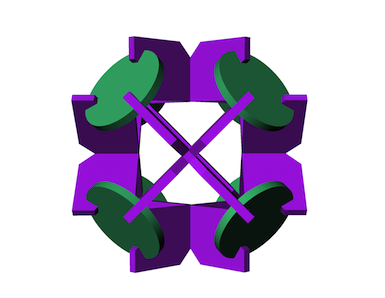
Here is the assembly that I put together in Solidworks and then rendered with some pretty colors in Rhino. It took a surprisingly long time to wrap my head around the mating of these pieces in Solidworks so this assembly is quite an accomplishment for me!
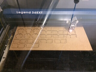
Next step: use the laser cutter! I brought the .DXF file from Rhino into CorelDraw and nested my pieces tightly so that I could fit it on a 10"x20" piece of cardboard. Thanks to Tom for this suggestion, it minimized the bending effect (potato chip) that the larger piece of cardboard would have had on my parts. For the laser cutter settings I used 25% speed and 50% power and a fire frequency of 1164Hz. I only have one part that didn't cut all the way through but it was cut enough to pop out of the cardboard. Even though I had measured the thickness of the cardboard as .169" and had made the slot clearance .165" to have a sort of interference fit, it was still an incredibly loose joint when I first tried to assemble the pieces. After some muddling and testing around with other clearances, I ended up using a .160" clearance which gives the joints a relatively nice fit (it still could use some work, but I didn't get the chance to run a third iteration).
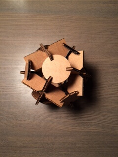
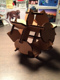
The final assembly turned out pretty good! If I were to do it again I'd rethink how the circle pieces join with the cross pieces, although the slanted nature helps for assembly it also makes a weaker joint. Perhaps some sort of extra edge on the joint which would snap into the cross piece would work better.
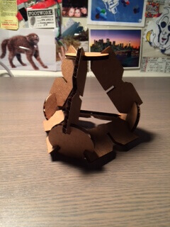
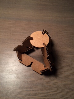
More muddling with the puzzle pieces and it turns out it can make a pyramid too! This assembly is even less stable than the original assembly, and it would really warrant a new kind of joint. All in all, though, this press fit kit was a success!
