The first part of electronics design this week was redrawing the echo hello-world board to become comfortable with eagle or the other electronics design tools.
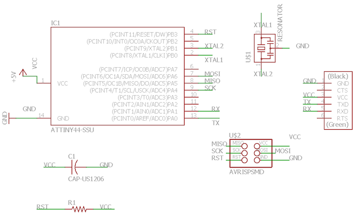
I don't have a lot of electronics experience so this was a very confusing yet enlightening week. I first put together the schematic for the echo hello-world. This exercise forced me to understand the connections on the board as well as how eagle works. I found it easier to not net components together in the schematic but instead label and name connections to keep my schematic cleaner. This also allowed me to isolate each component and very easily understand all the connections.
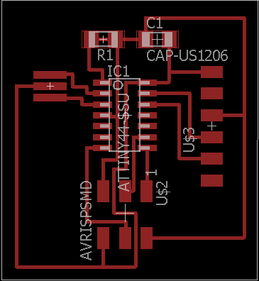
The next task was getting a feel for routing in the board view on eagle. I didn't want to use autoroute as I wanted to get a better feel for how boards are routed in general and to be able to double check my routes. I used the images of the board on the class repo to have a solid example of a good way to route the board. I also watched some tutorials online with tips and tricks and it seems like generally 90 degree angle routes are not the most recommended, so that was something I took into account later on in the design.
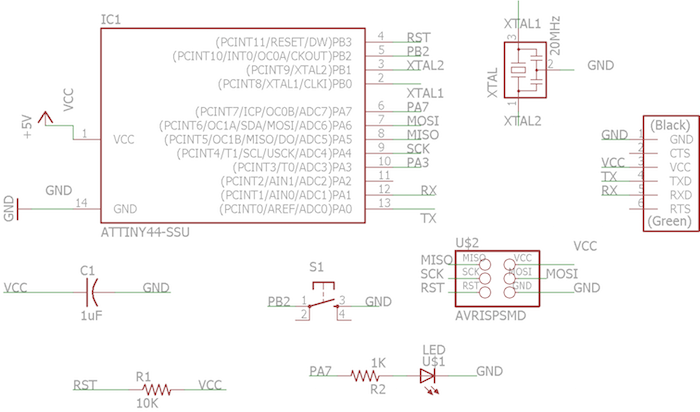
To add a push button and an LED the first step was to read the data sheets for each component. We were told that a 1K pull up resistor would suffice for the LED but I wanted to double check. Turns out Vf for the LED is 1.8 Amps and a current of 10mA and the current input is 5V. (Vin-Vf)/I=R so from that calculation the resistor would need to be 320 Ohms. I decided to stick with the 1K in case I read the data sheet wrong (I am still a beginner after all). For the switch I looked at a combination of people's past work, some tutorials and the data sheet to route the proper connections.
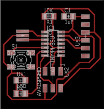
The routing for this board was a little more fun. Like someone in class aptly said "it's like a game of snake". I'm sure my board isn't professional looking by an expert's standards but I wass pretty happy with the outcome.
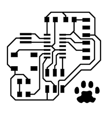

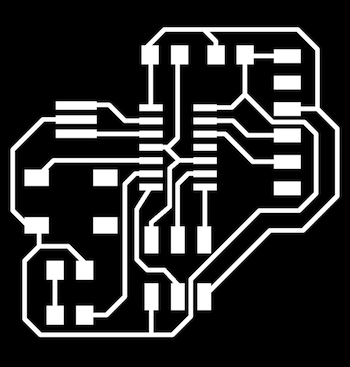
I exported the png files at 600 dpi in monochrome to be able to put them into fabmodules. I also ended up inverting the traces image on fabmodules as there were some weird remnants on Inkscape when I tried to invert. Since the program uses the image to create the toolpaths I wanted to make sure there wasn't extra junk leftover from image editting. The real question this week was, WHERE'S RUPERT? so I added a nice little paw print to the PCB. Subtle but necessary.
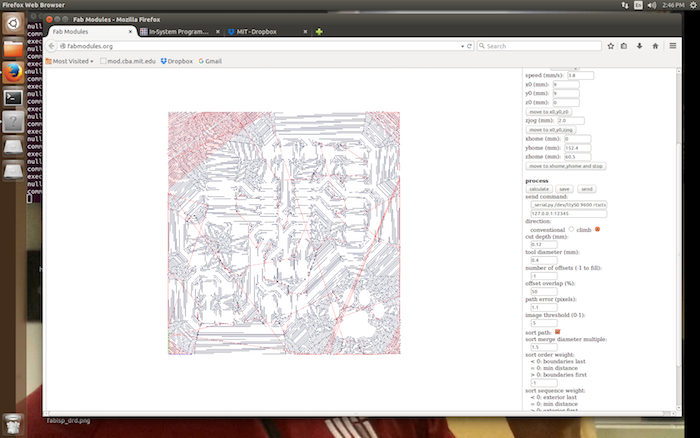
When I first brought the png into fabmodules there were a few areas that were too thin for the mill to make a path. This included between the pads for the Attiny 44 as well as some small corners etc. I went into eagle and manually changed this by decreasing the grid line and the sensitivity of moving the traces.
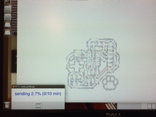
When I brought the new version back into fabmodules, everything was shown to have a mill path and it was ready to go. Settings: Speed 4.8, Cut Depth 0.12 Offsets 5.
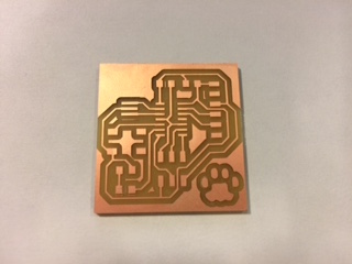
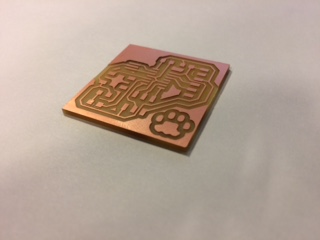
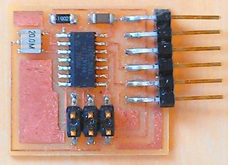
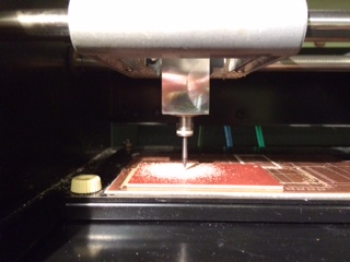
I was very happy with the quality. Last time I used the modela the traces came out fuzzy and there was a lot of post-processing to make it look nice, but this time it was beautiful right when I took it off the machine bed. (Probably the tools were in better shape, YAY!)
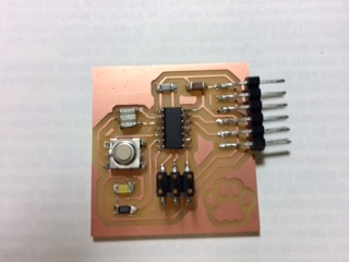
Ahhhh soldering... my... friend? Some of these components were interesting this week, particularly the resonator as there is a third pad that is directly beneath the component. I think I soldered it correctly but that remains to be seen for when I program the board. I was also unsure about the orientation of the switch, I think I made a knowledgable decision but it was not clearly stated in the data sheet, probably because there are multiple uses for the switch. Hopefully it all worked out, it certainly looks like a board with a switch and LED so that's wonderful!