I've never really programmed anything before so this was quite a long learning process this week. I decided to keep it as simple as possible by using the Arduino IDE as mentioned by the TAs. However, because we are not using pre-fab arduino boards I had to configure the IDE for the ATTiny44 specifically. I followed the instructions from high-low tech on how to configure the IDE correctly. As I'm using a mac I also needed to install the FTDI drivers so that my board would be recognized in the ports for Arduino. Settings: Tools-> Board: "ATTiny", Processor: "ATTiny44", Clock: "20MHz (external)".
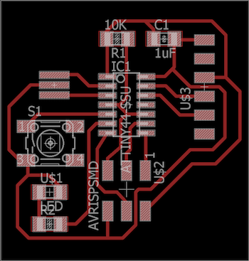
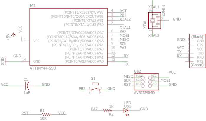
As I was using my hello echo-world board from week 5 I had to revisit the schematics from Eagle to remind myself of the pin numbers of the LED and the Button.
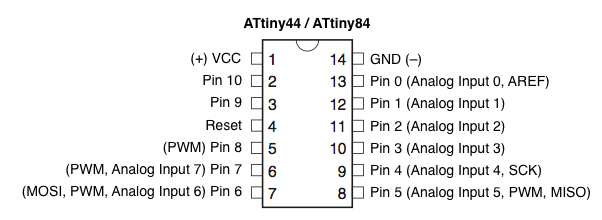
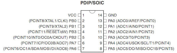
Turns out the Eagle schematic is a little misleading when it comes to which pin is which, especially in the case of which pin is considered which by the arduino. Above are the schematics that helped to guide me through the pins. My LED was on PA7 (port A 7) or pin 6 on Eagle, for arduino purposes the LED = pin 7. The Button was on PB2 (port b 2) or pin 5 on Eagle, for ardunio purposes the Button = pin 8 (see schematic).
AVR ISP mkII blinking LED
The first task was to get my LED to turn on at all. For this purpose, I used the AVR ISP mkII programmer (as I wasn't entirely sure if my Fab ISP was still in good shape) and the example code from the Arduino IDE for a blinking light (shown below).
Blink
Turns on an LED on for one second, then off for one second, repeatedly.
Most Arduinos have an on-board LED you can control. On the Uno and
Leonardo, it is attached to digital pin 13. If you're unsure what
pin the on-board LED is connected to on your Arduino model, check
the documentation at http://www.arduino.cc
This example code is in the public domain.
modified 8 May 2014
by Scott Fitzgerald
*/
// the setup function runs once when you press reset or power the board
void setup() {
// initialize digital pin 13 as an output.
pinMode(7, OUTPUT);
}
// the loop function runs over and over again forever
void loop() {
digitalWrite(7, HIGH); // turn the LED on (HIGH is the voltage level)
delay(1000); // wait for a second
digitalWrite(7, LOW); // turn the LED off by making the voltage LOW
delay(1000); // wait for a second
}
It took a while to find the correct ports, mostly because I had forgotten to power my board... oops. Once I had the last error had to do with timing being off. In order to fix this I had to burn the bootloader. From my understanding the bootloader is necessary as the internal clock of the ATTiny is a higher frequency than that of the regular Arduino. The boot loader helps to configure these two clocks in such a way that the timing written in the code translates correctly to the ATTiny.
Once I burned the bootloader and changed the pins correctly the LED LIT UP! WOOHOOOOOOOOOO! I programmed something.
Fab ISP Blink LED
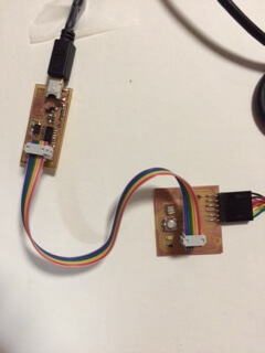
From the AVR ISP mkii I wanted to use my own Fab ISP to program (that way I could program from the comfort of my home instead of relying on the in-lab programmer). There were a number of errors, mostly from impatience or not having everything plugged in. The important setting difference is that the programmer in this case is the "USBTinyISP".
Although a lot of the fabISP and board fab was a bit of a mystery I'm really proud of being able to do something using both my own fabricated programmer as well as my own board. Exciting stuff!
Fab ISP and Serial Communication
Next step was to try and figure out how to use the button. For a while I had defined the button pin as just an input pin which I thought would suffice, but then I remembered that I had used a pullup resistor in the microcontroller in my schematic. I found that in the Arduino IDE it was easy, you just define the pin as INPUT_PULLUP instead. Next I wanted to know if pressing the button was closing or opening so I could know whether press was a HIGH digital signal or a LOW digital signal. For this I used Serial monitoring. However, on the ATTiny you can't use the regular serial communication from arduino, the work around is below and is in example Arduino code and a SoftwareSerial library.
SoftwareSerial mySerial(0, 1); // RX, TX
void setup() {
// put your setup code here, to run once:
mySerial.begin(9600);
pinMode(8,INPUT_PULLUP);
}
void loop() {
mySerial.println(digitalRead(8)); // put your main code here, to run repeatedly:
}
From the video you can see that when the button is pressed the serial monitor reads 0, when it's not pressed it reads 1, this means the pressed button digital write is LOW while unpressed signal digital write is HIGH. This was all necessary for my next programs.
Fab ISP Fade LED
As much as I love blinking lights I wanted to try and do something very slightly more sophisticated. Amanda helped me work on a program to fade the light from low brightness to high brightness. My LED pin was an analog input and therefore it allowed me to move from 1 to 256 range instead of the digital high/low voltage.
const int buttonPin = 8;
const int ledPin = 7;
void setup() {
// initialize digital pin 13 as an output.
pinMode(ledPin, OUTPUT);
pinMode(buttonPin, INPUT_PULLUP);
}
void loop() {
if (digitalRead(buttonPin) == LOW){
for (int brightness=0;brightness<256;brightness++){
analogWrite(ledPin,brightness);
if (digitalRead(buttonPin) == HIGH) break;
delay(5);
}
}
}
What I like about this code is that when I release the button the light will stay at whatever brightness I had released at. This is sort of interesting if you were to think about lighting applications and finding optimal brightness. Of course, I won't be lighting my room with LEDs but it's just a thought.
Fab ISP Fade and Blink
I wanted to compile both the blinking and the fading code by making the first press of a button run the fading LED while a second push would make it blink and a third push would turn off the LED. For this I looked into counters. The idea is that the loop itself counts how many times the button has been pressed (in mod, so it repeats) and then you must use if statements to program what happens on each individual button press. Again this is not highly sophisticated but I learned about counters and am now beginning to understand how much I could probably do with this little board and some code.
const int buttonPin = 8;
const int ledPin = 7;
int buttonPushCounter = 0;
int buttonState = HIGH;
int lastButtonState = HIGH;
void setup() {
// initialize digital pin 13 as an output.
pinMode(ledPin, OUTPUT);
pinMode(buttonPin, INPUT_PULLUP);
}
void loop() {
buttonState = digitalRead(buttonPin);
if (buttonState != lastButtonState) {
if (buttonState == LOW) {
buttonPushCounter++;
}
else {
}
delay(50);
}
lastButtonState = buttonState;
if (buttonPushCounter % 3 == 0){
digitalWrite(ledPin, LOW);
}
if (buttonPushCounter % 3 == 1){
for (int brightness=0;brightness<256;brightness++){
buttonState = digitalRead(buttonPin);
if (buttonState != lastButtonState) {
if (buttonState == LOW) {
loop();
break;
}
}
analogWrite(ledPin,brightness);
delay(5);
}
}
else if (buttonPushCounter % 3 ==2 ) {
digitalWrite(ledPin, HIGH);
delay(100);
digitalWrite(ledPin, LOW);
delay(100);
}
}
As seen, the first press leads to a fading loop, the second press blinks the LED and the third press turns it off. I hope to explore a little more later on other things I could do with the LED but I'm starting to get an understanding of how I can use this programming language to work on some of the electronics aspects of my final project.
Other Interesting Lessons about Connectors
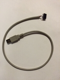
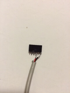
For a while there were only a few FTDI cables in the lab, but since I wanted to program at home Amanda gave me the idea to make my own connector. I took an old USB cable, stripped it and soldered it according to the USB schematics and my board schematics. This was a total pain to solder and it was not a pretty cord at all. However, it did supply power to my board. I thought I was good to go and I could do everything at home, until.... dun dun dun.... it didn't work. It did supply power but my board was no longer being recognized by the Arduino IDE in the port. I think this was due to connecting the RX and TX cords incorrectly, there was some confusion in the USB schematics. I'd be interested in making a new one just to see what had happened. I guess it's useful to just power and use the program but not useful for programming. I ended up getting my own FTDI cable but for a brief moment I felt really cool with my self-fabricated version.
All in all, it was a successful week, I'm still not feeling totally fluid and natural in the Arduino version of C but hopefully through some more googling and tutorials I'll get to a better functionality, at the very least to be able to play with some ideas for my final project. YAY CODE.