
Servo
As part of my final project I want to use a servo to open the lid of the catbowl automatically. It was obvious, therefore, to use this week to learn how to control a servo.
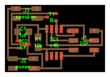
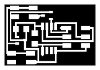
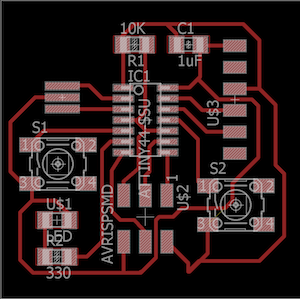
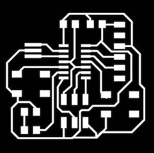
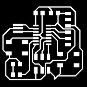
I wanted to get back into Eagle, so I took the template hello.servo.44 board design and added an LED. The LED was purely to show when my board was being powered, and the rest of the board was the same as the template. I forgot how difficult routing was but it was a good task to keep learning new strategies for component orientation.
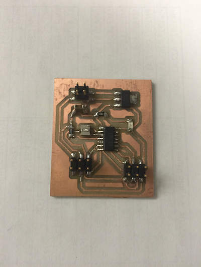
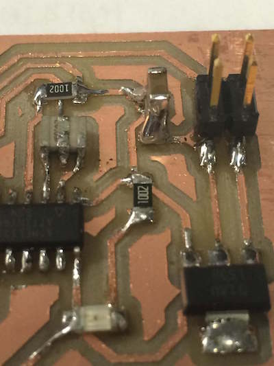
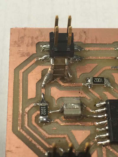
On the template there is a 22uf capacitor as one of the components. After looking through the inventory of the electronics lab, it was clear that we did not stock these particular capacitors or those of higher capacitance. Thanks to Dan's suggestion and looking up basic properties of capacitors I decided to stack 3 10uf capacitors instead. As long as the capacitance is greater than or equal to 22uf the board should work fine. Furthermore, capacitors in parallel is a simple addition of individual capacitances.
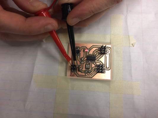
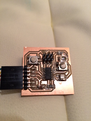
As I wasn't quite sure about how to power the board or how to connect the servo properly, I decided to just double check that the board was being powered correctly. I used a power source and just touched the positive and negative leads to the voltage in and ground pins on my board. The light lit up so I was relieved that the board fabrication went alright.
From there I programmed the board. I never configured my computer properly for programming directly through the terminal so I just copied and pasted the template C file into the arduino IDE to compile. It worked! Now I'd like to experiment a bit with the parameters according to what I want for my final project.
Speaker
My final project idea also incorporates some sort of feedback for the cat who is not supposed to eat from the bowl. For this I figured a loud beeping would suffice. So I've decided to also try the speaker output device.
For this board I'll simply be using the template for the hello.speaker.45 board. (Eventually I will integrate all of these components into one board, but that will be my electronics fabrication for the final project.)
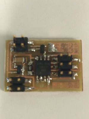
During fabrication I had some issues with fab modules and connections to the roland mill. The USB0 connection was not found. The connector somehow got changed from the correct connection so once that was changed I could see the USB0 port and the roland mill was talking to fab modules. However, part of the end of the command line had been changed and so the machine did some abstract art on my stock instead of milling the traces. Once I changed the command line back to default everything went swimmingly.
I was impressed with how small this board and its components were. The mosfet and regulator were a little difficult to solder just because they were so tiny, but thanks to all the practice it was not a total nightmare. I'm starting to really enjoy soldering too which is nice.
Again I programmed with my FabISP and used the template code to program. My speaker has a lot more noise than the video example online, I'm not sure if this is due to the speaker itself or the connections on the board. I still want to look into that before choosing a speaker for my final project. As much as I love a dialup sound I think for my final project I'll just end up making a constant loud beep. All in all, this week was successful in preparing me and quelling my fears of how my final project will take shape. WOOHOO!
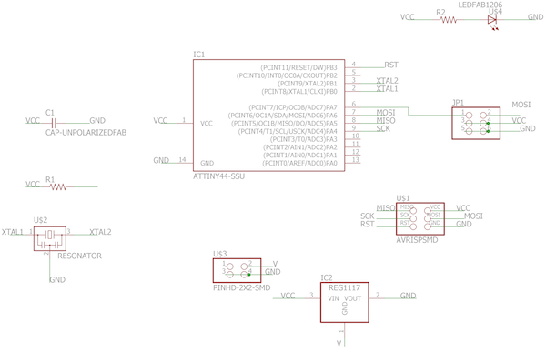
IR LED
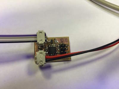
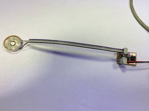
The third output device I wanted to make was a small LED Remote to mimic the unique cats when they would want to try and eat from the cat bowl. The IR LED is not much different from a regular LED except it's much harder to know whether or not its working.
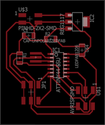
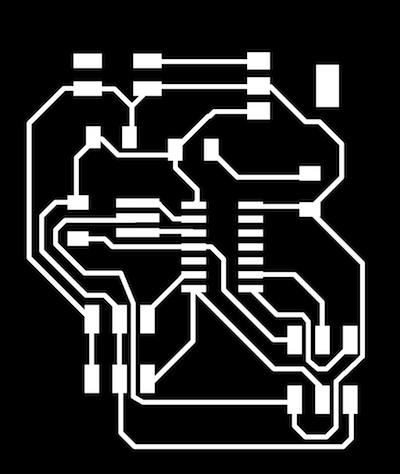
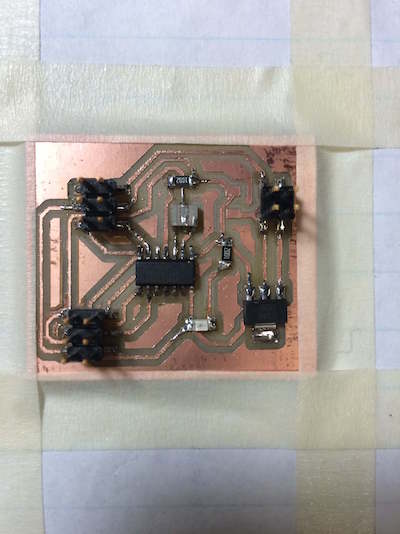
This time around I was feeling a little time crunched and tried to use autorouter in eagle to make my traces, unfortunately this meant that I was not paying attention to some main design rules. Somehow the trace for ground was connected to VCC. I ended up just cutting away with it with a razor but I'll be sure to manually route my boards from here on out, not worth that terrifying moment. Unfortunately, the traces were really messy and even after using a straight edge to score them it wasn't looking all that great. I'd like to figure this out, it seems my boards get progressively worse every week in terms of trace quality which isn't too good.
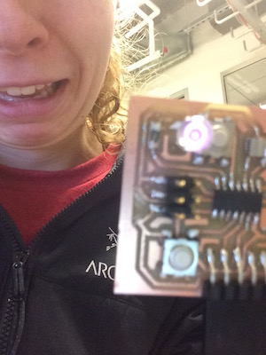
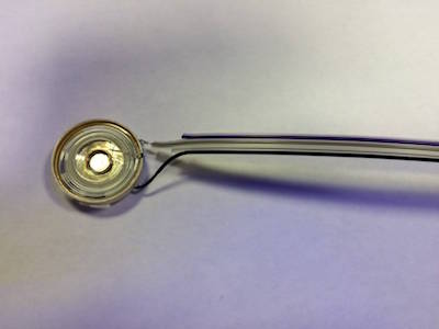
For a while I was trying to use the camera on my iphone (the back camera) to see whether or not the LED was lighting up, and it seemed like it wasn't lighting up. Although the data sheets for the LED said it required a 330 Ohm resistor before it, but after looking up some tutorials I found that a 100 Ohm would probably work better. Similarly, using the multimeter the amount of power going through the LED was below the rating of the LED. After some changing of resistors and changing code etc. the LED still wasn't working. So I looked it up on the internet, turns out that iPhone 5s' back camera has an IR filter, no wonder I couldn't see it, BUT the selfie camera works! Thus the beautiful photo above.
Unfortunately, the switches weren't working too well, it also seemed like there might be a connection between the outer copper and one of the LED traces as it kept turning on every time I touched part of the copper. If I choose to move forward with different frequencies of IR light I'll need to make sure this board is really well made and a little more robust. The code itself was pretty much the same as the switch and LED from previous weeks. This worked out pretty well but I'd like to make sure that it is powerful enough for the receiver as well. This will come next week with input devices.