redraw the echo hello-world board
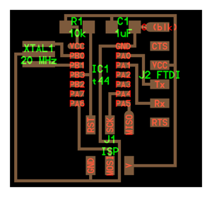
Using EAGLE CAM tool, I redrew the ftdi hello echo board. First, I imported the components utilized in the board into the schematic and used "NET", "NAME", and "VALUE" to define connections between them.
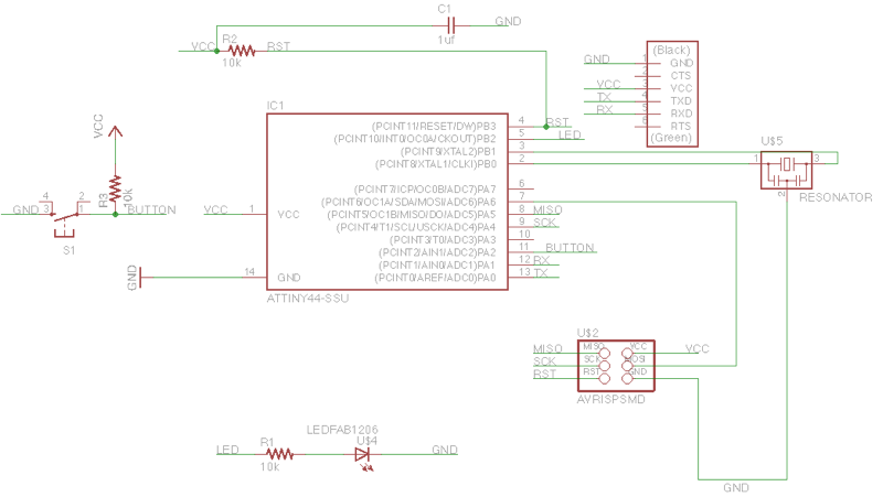
add (at least) a button and LED (with current-limiting resistor)
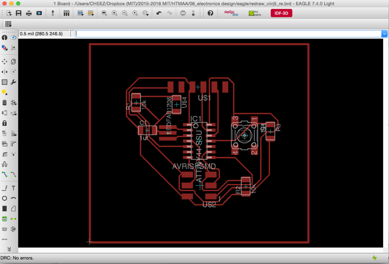
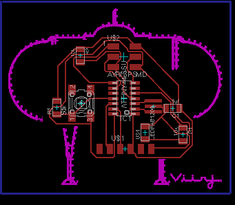
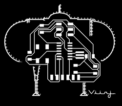
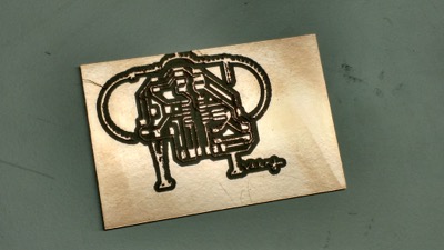
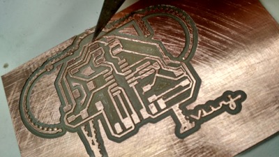
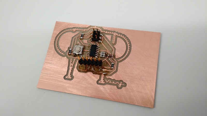
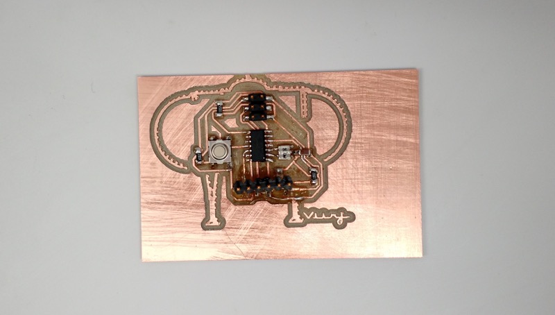
I wanted to make a board in an arrangement of my mini submarine drawing so I uploaded a bitmap file and moved the board layout over it. The *move* option for eagle is pretty unintuitive: >select all using the *group* option. Then, select the move tool and right click on top of your layout. Then click *move group*
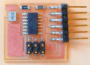
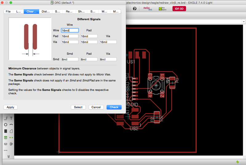
check the design rules, and make it
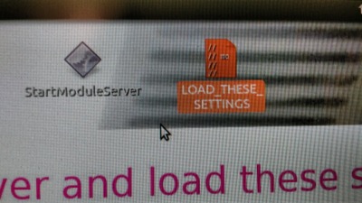
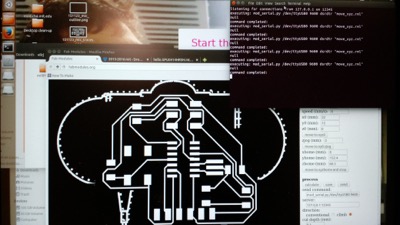
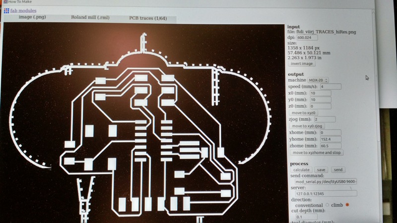
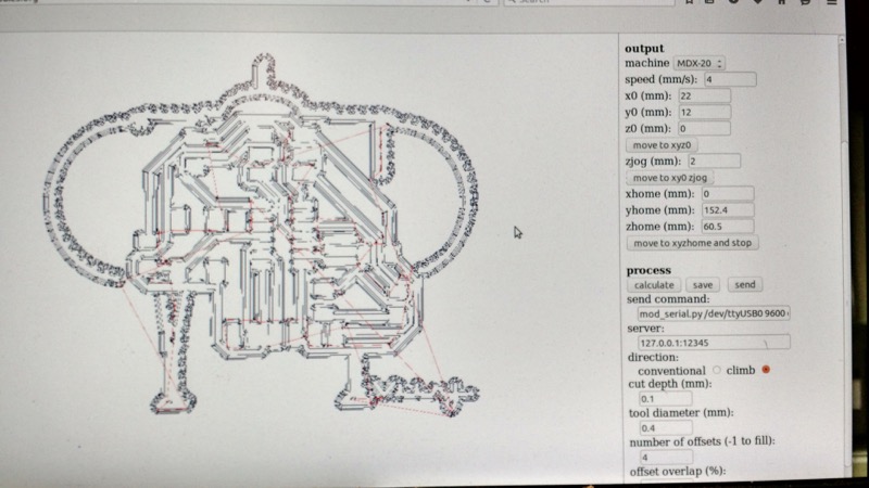
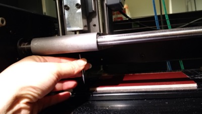
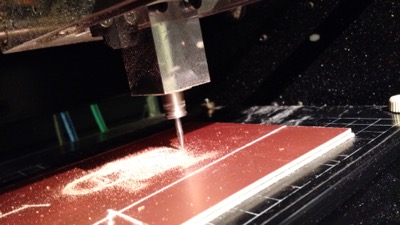
To begin milling, first the server needs to be started. Once that's up, load the settings into the FabModule. Following the selection options, I loaded the design, selected the endmill and zeroed the modela to my copper board. Finally, I select calculate to generate the tool path. Depending on how it looks, I might increase the number of offsets from 4 to 7-15 to get a cleaner finish on the leads.
extra credit: simulate its operation
Tools:
eagle > LTSpice? > modella mill > solder