Input/Output Devices 2015
Hotshoe Microcontroller
A hotshoe flash exploration
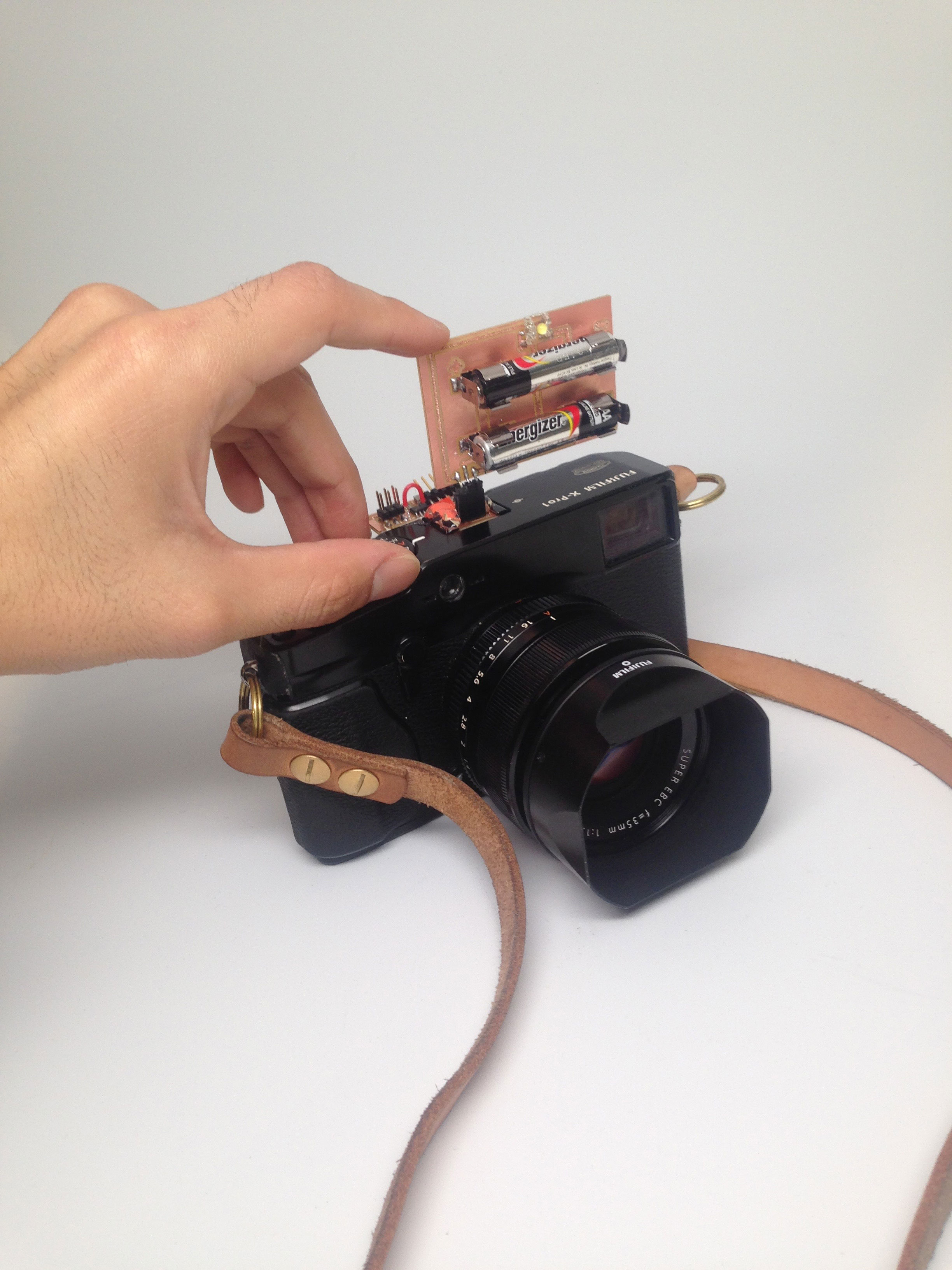
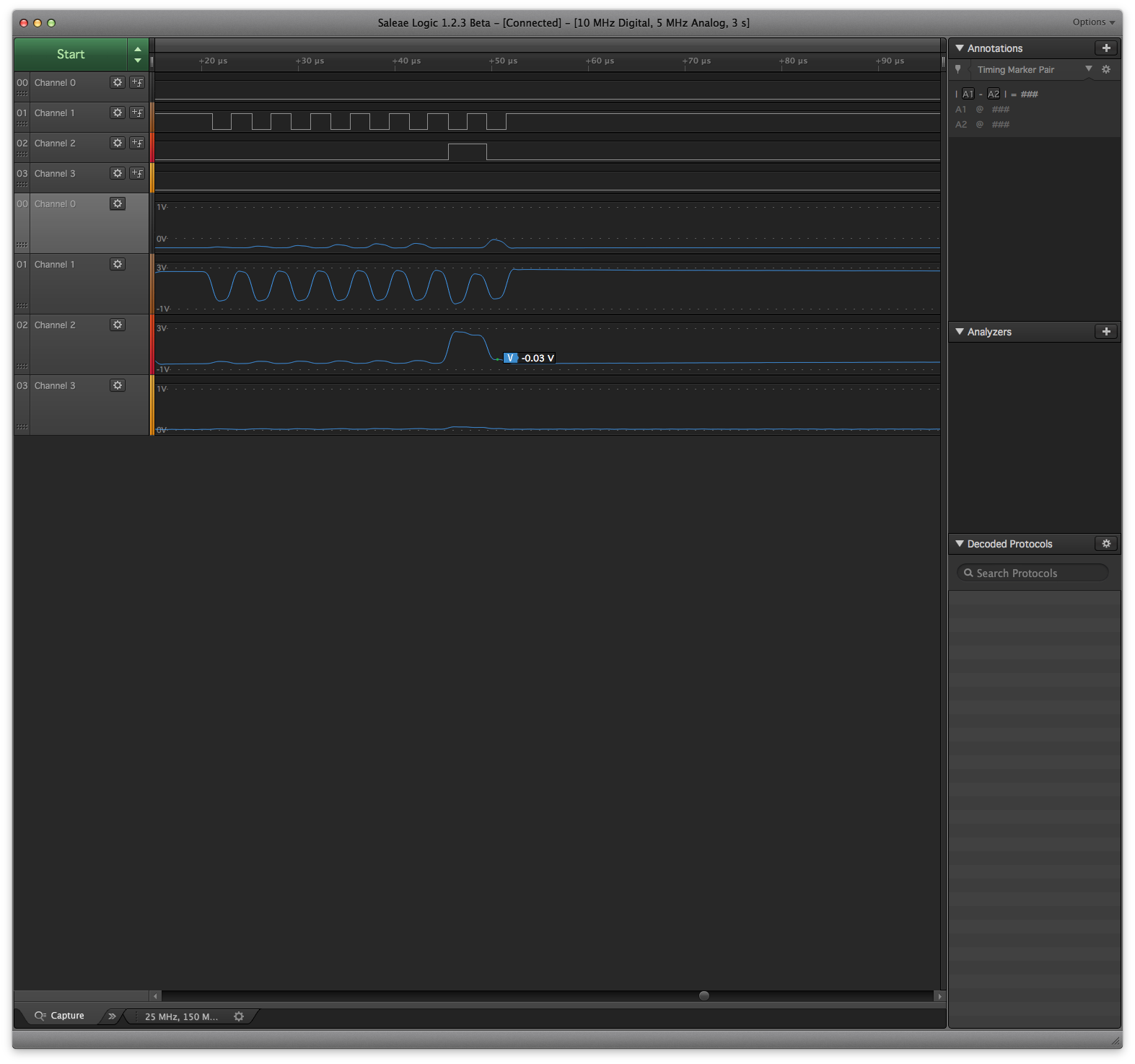
This week we needed to use a microcontroller to create an output. Early on in this course I knew that I wanted to do something with a camera, since I have a general interest for photography. I began by reading the signals that the hotshoe pads output once the shutter is released, as they are used to trigger flashes. I first created a breakout for all the pads on the hotshoe using pogo pins. Using a logic analyzer, I found that all contacts give an output. (using Salea logic analyzer)
I decided to incorporate the microcontroller in the hotshoe adapter, leaving the batteries and LEDs as an external board.
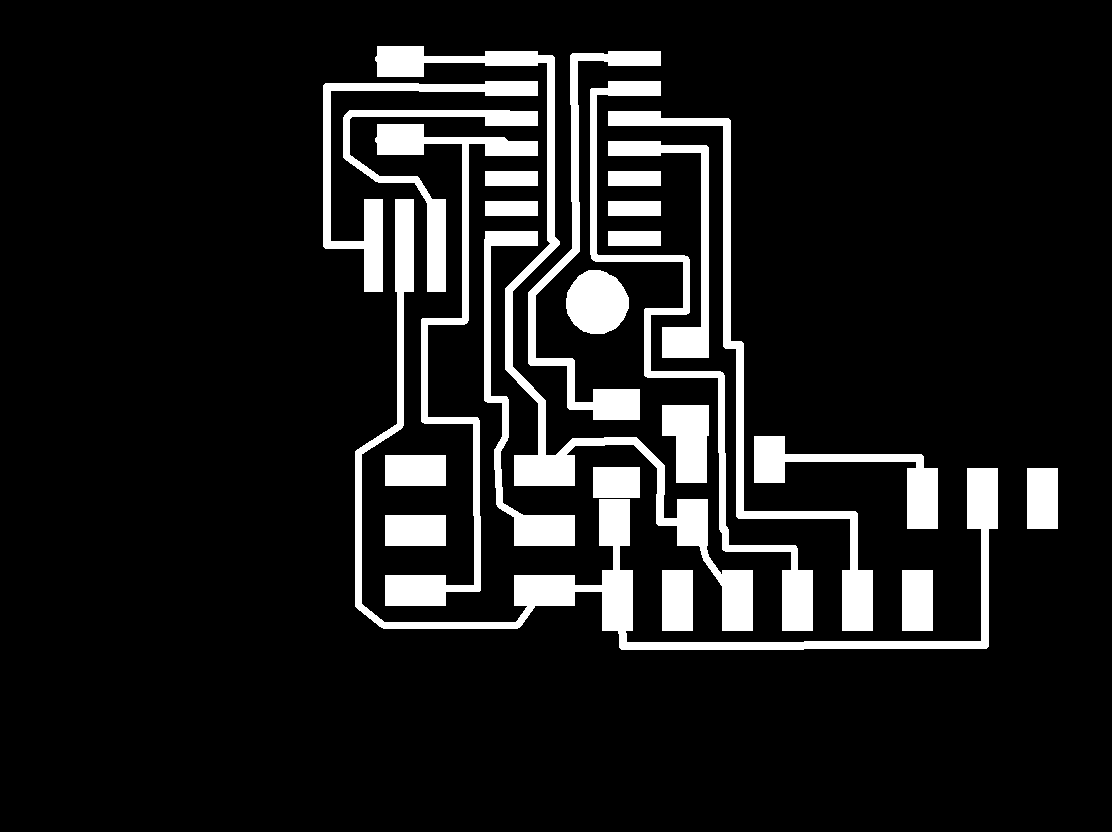
The first functional iteration of this circuit did not allow enough space for the pogo pin to poperly align to the pad, so I had to redesign the circuit board.
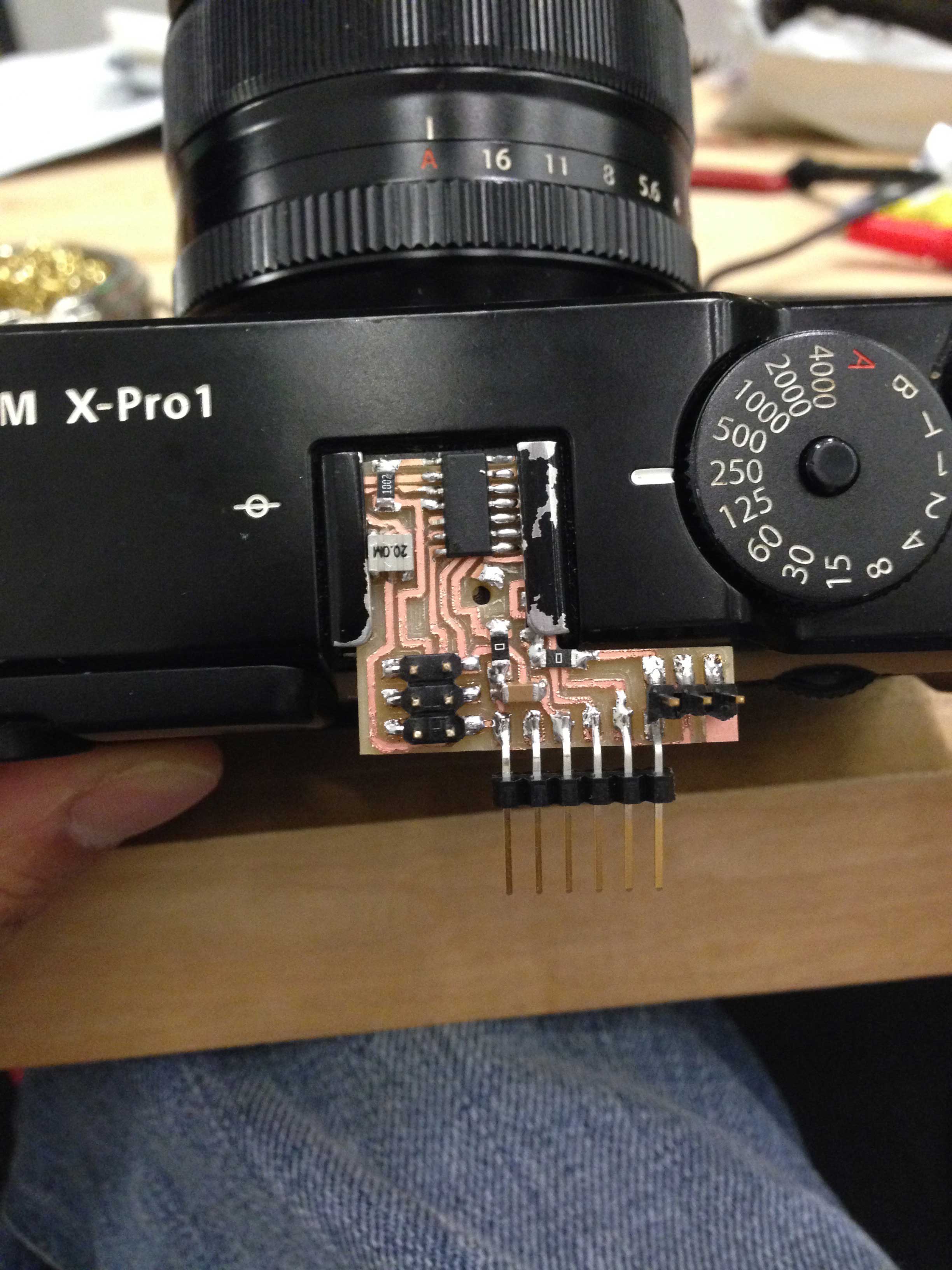
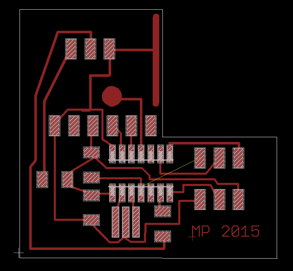
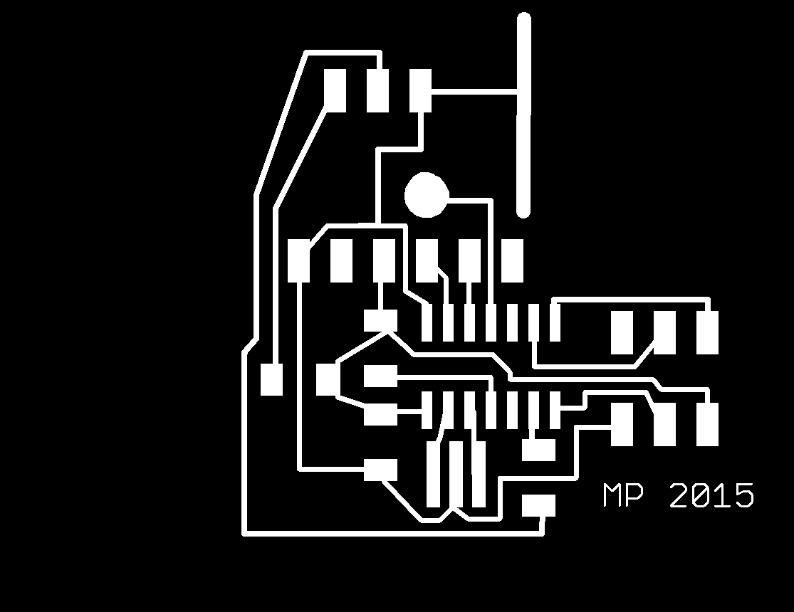
This is the final design for the hotshoe microcontroller. I soldered a jumper for the ISP, which will be removed once happy with the final product.
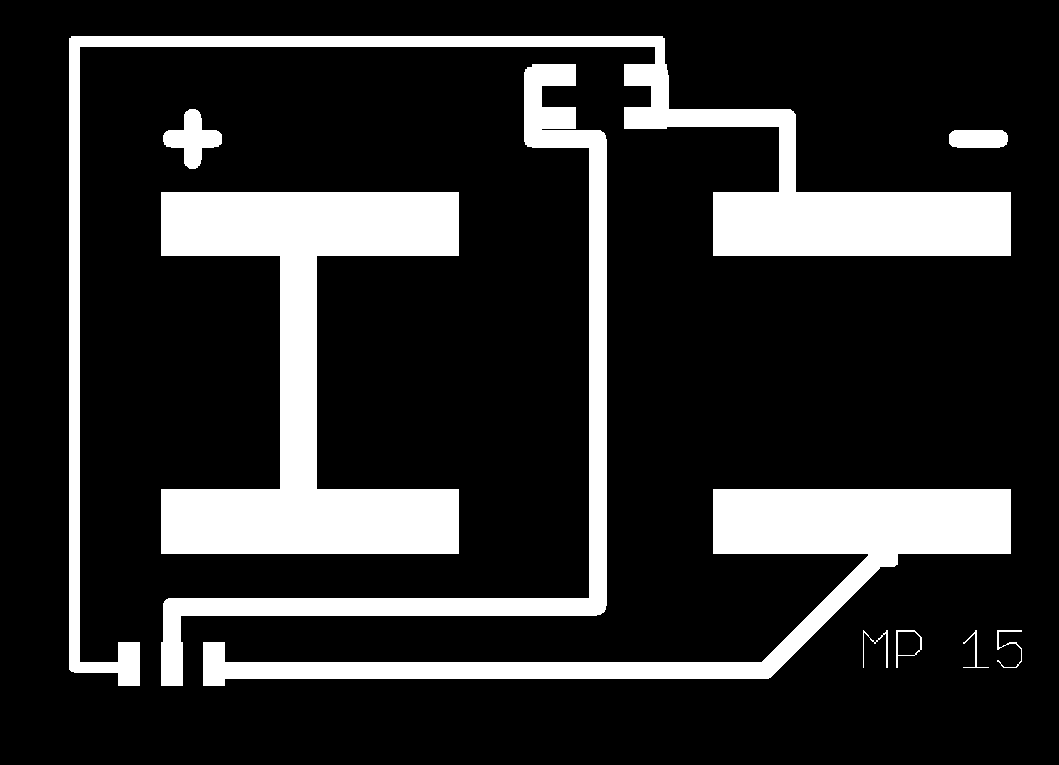
This is the PCB with battery holder, LED, and connector pins.
The next steps are to make an array of leds and add a transistor to allow more power to the LEDs.