Hydro Reflective Caustics Mirror Ball

Hydro Reflective Mirror Ball (cube)

a disco mirror ball using caucstics effect with water

Concept

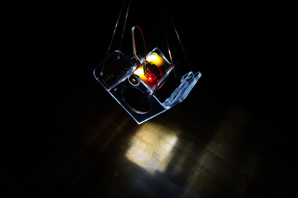
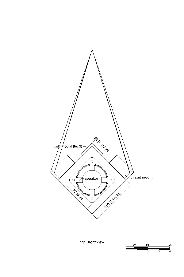
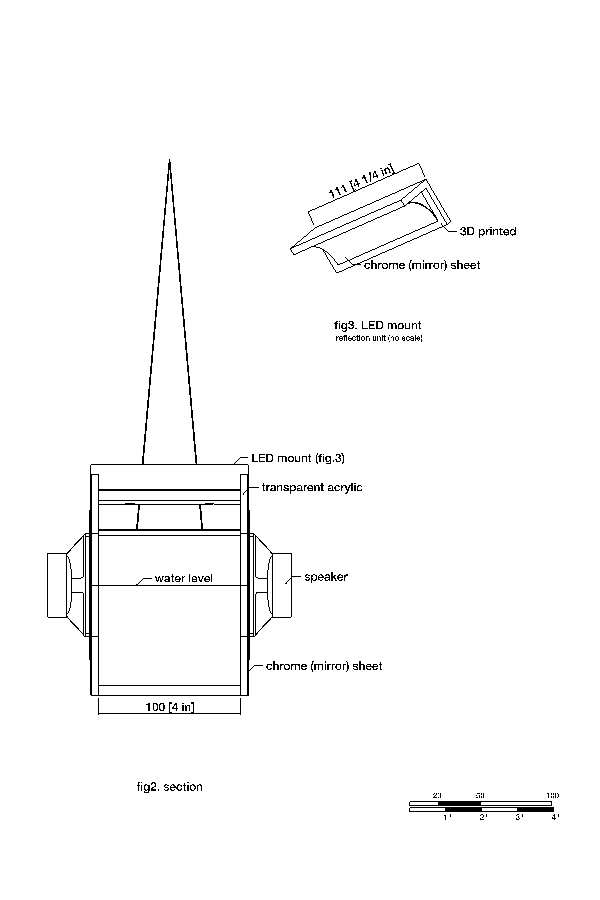
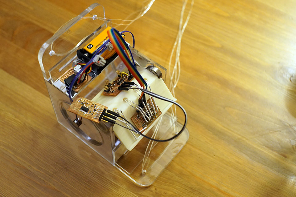
For my final project I decided to make something that functions as a disco ball, but uses water and the caustics effect for scattering light. It consists of a vibration unit and a bright LED with reflective and transparent materials.

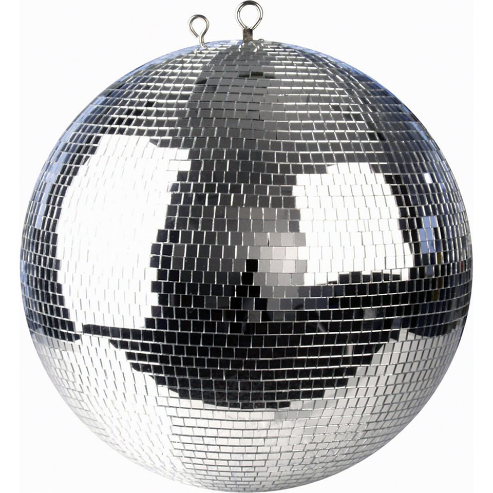
Fig1. Traditional disco ball

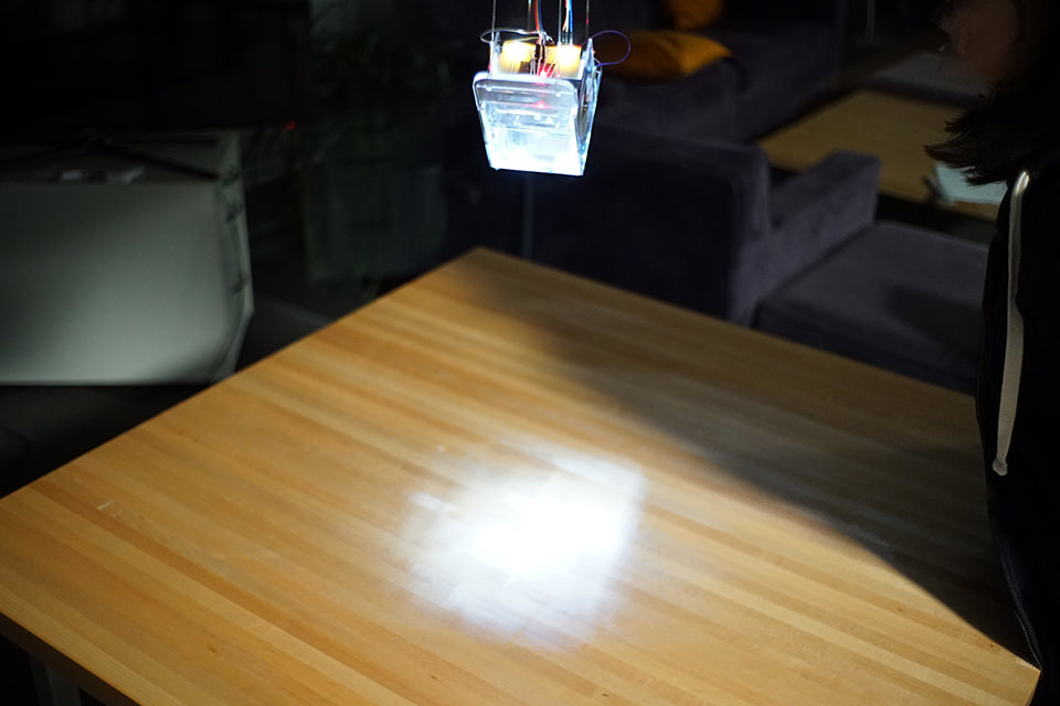
Not only as a discotect utility, I thought that this will be a nice light source for my room, more over a handy thing to distract our baby that is expected in January. Fig.2 from Fig.4 shows a possible light pattern to be projected

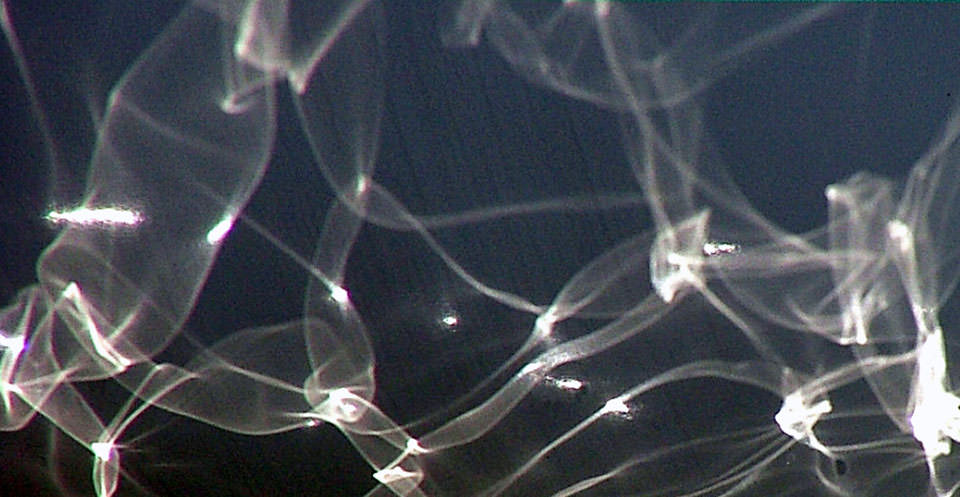
Fig2. caustics effect example

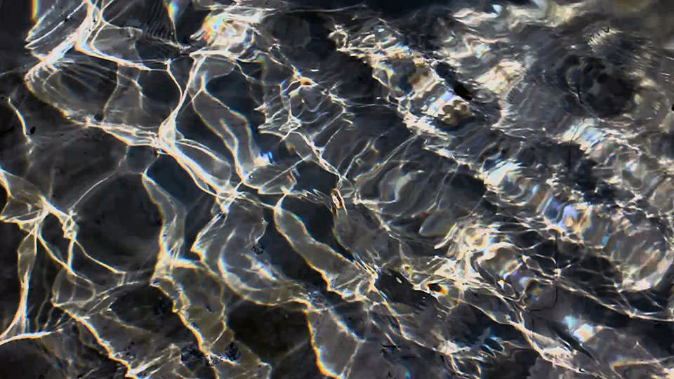
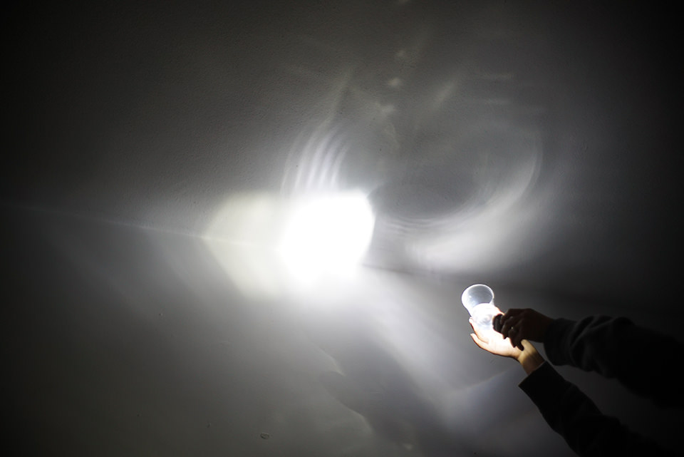
Fig3. caustics effect example

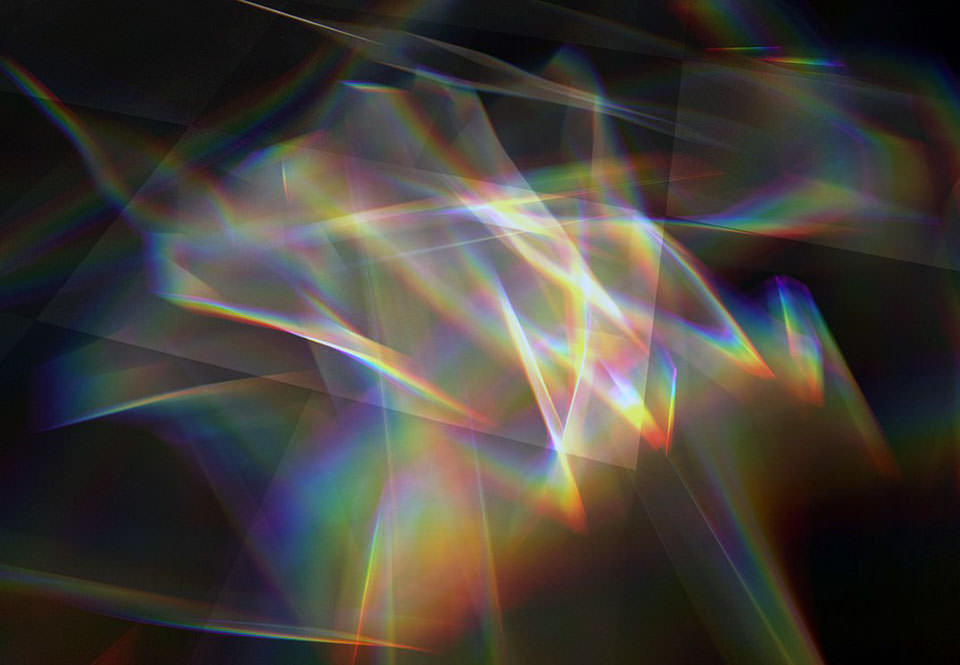
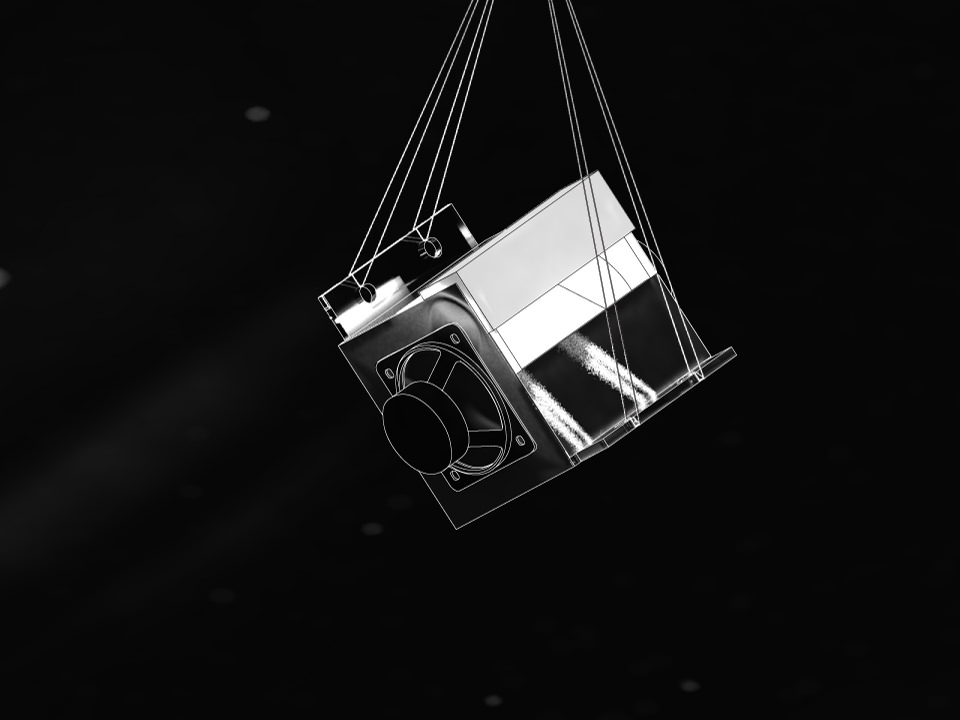
Fig4. caustics effect example

Experiments

I conduced a little experiment to see the actual effect using a plastic cup and a bicycle flash light. It looked promising!

Fig5.

I thought that I can imitate how the flash light diffuses light using a reflect concave surface.

Fig6.

Rendering and Planning

I simulated the caustic effect using 3d rendering. Rhinoceros was used to model. As a result after making this gadget, the simulation was very similar to what I have here.

Fig7. 3D model

At this point, I'm not sure about the right distance and the necessary light strength to be effective as a room light source. Another good thing to know before hand is the strength of the vibration source. I'm using a 77mm speaker to produce the vibration at this stage, but switched to using a vibration motor.

Fig8. casting the caustics.

Looking back from the final result, I should been selecting a stronger motor, or reduce water mass to make sufficient waves.

Fig9. caustinc top view.

drawings PDF

Fig10. initial design view from the front

Fig11. side and LED mount details

Reference and previous attemps

There was no attempt making a caustic mirror ball before in how to make nor fab-academy class archives, while there was 224 making mirrors in use, but no caustics as a optical effect. The following is some art pieces, projects and products that is related.

  1. may the force be with you from Teo Park.
  2. Solar Powered RainbowMaker Double Swarovski crystal from Kikkerland.
  3. solar death ray water aqua lens with 1/3 killowatt heat energy grid free enery.

Ordering and Scheduling (12/3)


product store quantity price subtotal (arrival)
Hobby Vinyl - Gloss Vinyl Oasis, 12in x 10ft amazon 1 19.99 19.99 12/5
Acrylic Sheet, Clear, (0.118") 12"x12",8pack amazon 1 29.21 29.21 12/7
SCIGRIP 16 10315 Acrylic Cement amazon 1 6.75 6.75 12/9
SCIGRIP 3 10799 Acrylic Solvent Cement amazon 1 6.03 6.03 12/9
Vibration Motor ROB-08449 sparkfun 2 4.95 9.9 12/9
Speaker - 0.5W (8 ohm) COM-09151 sparkfun 2 1.95 3.95 12/9
LED - Super Bright White (25 pack) COM-09850 sparkfun 1 7.95 7.95 12/9
Super Bright LED - White 10mm COM-11118 sparkfun 2 1.50 3.0 12/9-?
VXB 608 ZZ Skateboard Bearings amazon 1 8.17 8.17 12/7
Vibrating Mini Motor Disc PID: 1201 adafruit 2 1.95 3.90 12/13
Premium Female/Female Jumper Wires - 40 x 6" PID: 266 adafruit 1 3.95 3.95 12/13
Beadalon ELASTICITY elsatic stretch cord 0.39in (1mm) 82ft (25m) roll Brick Art materials 1 6.50 6.50 (12/14)
Shipping Fee (Adafruit and Sparkfun) Adafruit, Sparkfun 8.39,4.13 1 12.52

TOTAL:$121.77

total $83.73 Hope this is it!! I have coordinated the schedule of making my mirror thing.
update 12/6: I ordered a brighter LED, and bearings, making a total of $94.9... update 12/10: LAST order. I got nervous about the vibration motors, ordered backups from adafruit and Jumper wires as well for making the final product look nicer.update 12/14: bought elastic from local Brick Art Materials and added shipping fee, Grand Total is $121.77.

I planned to use three boards, reuse one from previous weeks, and make two boards. As Neil was constantly suggesting, this is for easy debugging and also wanted to make use of the experience of networking attiny44s in the output / networking and communication week. Persisting to modularity also makes my project flexible for future improvments. The first board is for getting power and contorling vibration motors. This board will work as a hub communicating the input and the output boards. The input-board will be a microphone sensor unit reusing what I made for input devices. After getting signals from the input, The hub board will control the motors and send signals to the LED board that handles the light source.

Fig12. the vibration motor controller (version 1)

As you can see from the board, I was initially planning to control the motors directly from the pins. This will not be a efficient power source because the motor has a 85mA starting current which is higher then one pin can source(-40,50mA). With this remark, Parash advised me to use a H-bridge because I can use Neil's dc motor example. The next day however, I was choosen from the random generator and needed to present the current situation for the final, Neil pointed out that a N-MOSFET will do the job, since vibration motors do not have direction. This started a journey for understanding MOSFETs, and Ali helped me a lot for this. The diagram on the left shows the the connections.

Fig13. mofset diagram

Jeff verified my understanding of and I proceeded to board design.

Fig14. schematic

Fig.15 is the final version of the vibration motor board. The reason I have a little extra pad of copper for #1 pin and near the right bottom corner is that I forgot to connect the tiny VCC pin! Although a dumb-easy mistake, I left it to show that I can fix afterwards and I acctually liked the apperance. I also replace the 3.3V regulator to a 5V regulator, since the PWM was working than expected, and lowered my motor output force.

Fig15. vibration board (version2)

After a few struggles mentioned above, the right shows the final appearnce of the vibration motor board

Fig16. tentative soldered board

The LED board was straight forward, I have extra pin break outs for a bigger and stronger led. (This will not be used since now I know I cannot source a 80mA LED directly from the micro controller.)

Fig17. led board

Fig18. led board components

milling and soldering

The milling was not good quality, lots of stringy reminants while cutting, may be the endmill was worn out.

Fig19. milling having lots of stringy remains..

I tried to debur the edges, just like previous weeks, but the rought traces was too rough enought to scrape off the board. I milled the board again, and seems that the endmill was replaced to a new one, and went perfect as usual. Another tip I found is for double sided boards, its sometimes better to debar the back side in order to get a flatter surface.

Fig20. destroied trace

I soldered everthing I need within the shop inventory...This was the first iteration of making boards, the soldering was good enough, but while going through the vibration boards, I had the chance to use the other modela (one in the right side), and that one milled perfectly without no reburring required.

Fig21. partial solerding before parts arival

cut trace and 3d print modeling

I asked Tom to 3print the top part. The reason is for precision, and wanted to try this since I didn't have time to try on the 3dprint week. Thank you Tom!!

Fig22. 3d printed part

programming

Since I have three boards talking to each other I will need the same number of c-code.

  • LED: Plain old high and low control using four pins of the LED board. Below is the coresponding char for the number of lights.
    • '0' : all off
    • '1' : all on
    • '2' : middle leds on
    • '3' : outer leds on
  • COMMUNICATION: selected UART, RS-232 for communicating. Concern in motor noize. needed to adjust the bit_delay_time for each chip. The Motor board needs to have a interupt version of get_char. I had a concern in MOTOR noise, but fortunautly did not affect the result.
  • MOTOR: Throughout the whole project the most trouble was to make the motors working. I couldn't understand the invert of the pin and the motor, and I still can't. In books and video tutorials, it says that if I apply +V to the gate, voltage/current will flow through D-S, but the results are the opposite. Setting the gate LOW will direct current to the Drain-Source. With this, the micro controller is PWM controling the strength of the vibration. Neil's motor example used microseconds _delay_us, but did not render good in the scope, (maybe because its through the regulator or mosfet), alternatively mine worked with milliseconds _delay_ms. Eventually through trial and error, I found a good range of high-low pitch.
  • MIC: needed to adjust the output to make it talk with the Motor board. I took the same concept of getting a baseline (a mean within a number of readings, this case 100) fron Neils python code for analog microphones. baseline = 0.01 *(float)result + (1.0-0.01)*baseline While getting this value it returns the maximum difference within the cycles and sends them to the hub board.

led_control.c,led_control.make,vibration_motor.c,vibration_motor.make,microphone.c,microphone.make

laser cutting and 3d printing

I used a 1/8" (3mm) thickness acrylic. The settings for the epilog laser was. speed 10, power 80 and frequency 5000Hz. The hole for bearings fit perfectly.

Fig23. clear crylic laser cutted

The print came out beutiful, thanks again o Tom.

Fig24. 3d printed with support material

Roughly taking apart the support material.

Fig25. 3d printed support

Dipped through the solution to take away the supports. I had to sand a bit to install the bearings.

Fig26. 3d printed part

assembly and integration

I made the reflector using chrome vinyl that I bought.

Fig27. chrome sheet for reflector

I used SCIGRIP acrylic solutions both welding cement and adhesive to fix the acrylics.

Fig28. hardware assembly

I connected the boars and tested that all my programs are working. The video below shows that I succeeded to implement the neccessary functions, Motor contorl, led control, and communicating. I was happy to see this working without any inteference of motor noise.

Fig29. electronics assembly

The top mount was fixed using doube sided tape. While I had a few iterations on soldering parts to a board it was surprisingly difficult to solder the wires in mid air.

Fig30. top mount assembly

combining was easy, and I found it very combinient that the top part is easy to distach. Also the overflow water holes functioned just as intended avoiding to wet any of the electronics and battery.

Fig31. combining it together

I tested hanging on a air duct in my lab. I learned that I shoud not put in water with low tempurature for condensation.

Fig32. A Test to hanging from the ceiling.

For a final conclusion, the vibration motors was not strong enough to make a big differece, I may tweek the code to make it stronger, and replace motors.

Fig33. subtle effect...