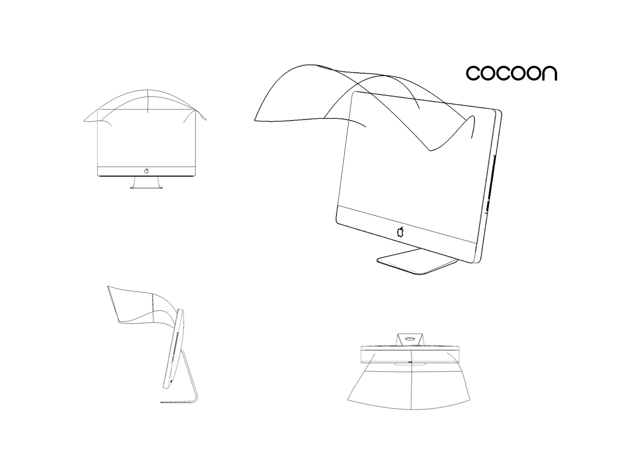
COCOON
Concept
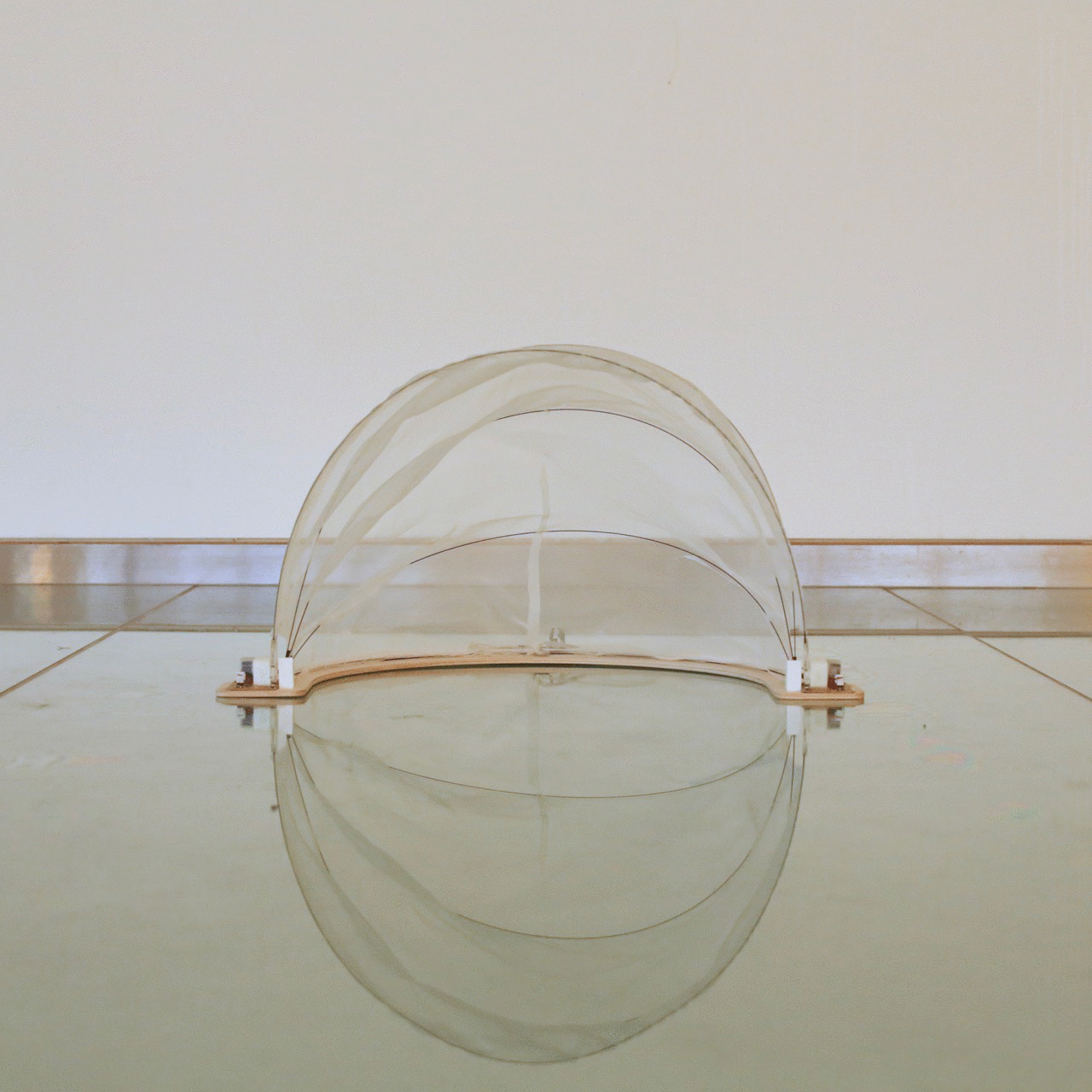
The ☾ Do Not Disturb mode brought into the open-plan office environment. Self-regulating … when you need it. In the tumult of a collaborative studio, the quiet of a library.
Design Spectrum: symbolic (conventional, must be learned, e.g. ABC), iconic (possesses some of objects qualities, e.g. smilie), indexical (doesn’t resemble object but is physically connected, e.g. trace)
Development and CAD of Mechanical Parts
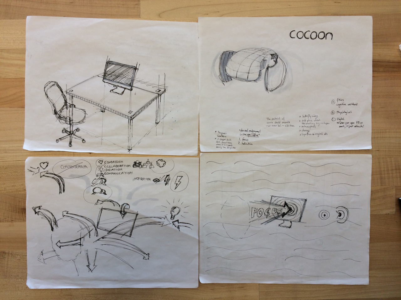
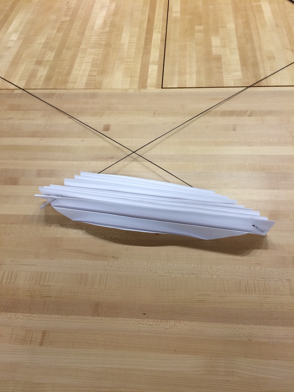
My vision for the mechanism was something small that elegantly would expand into something big. This is not an easy task and brought me study things like satellite solar panel mechanisms. I found solid carbon fiber rods that are very thin, light-weight, and so flexible that they could be rolled up. So I started working on a spooling/expanding mechanism actuated by DC motors that would deploy a paper roof.
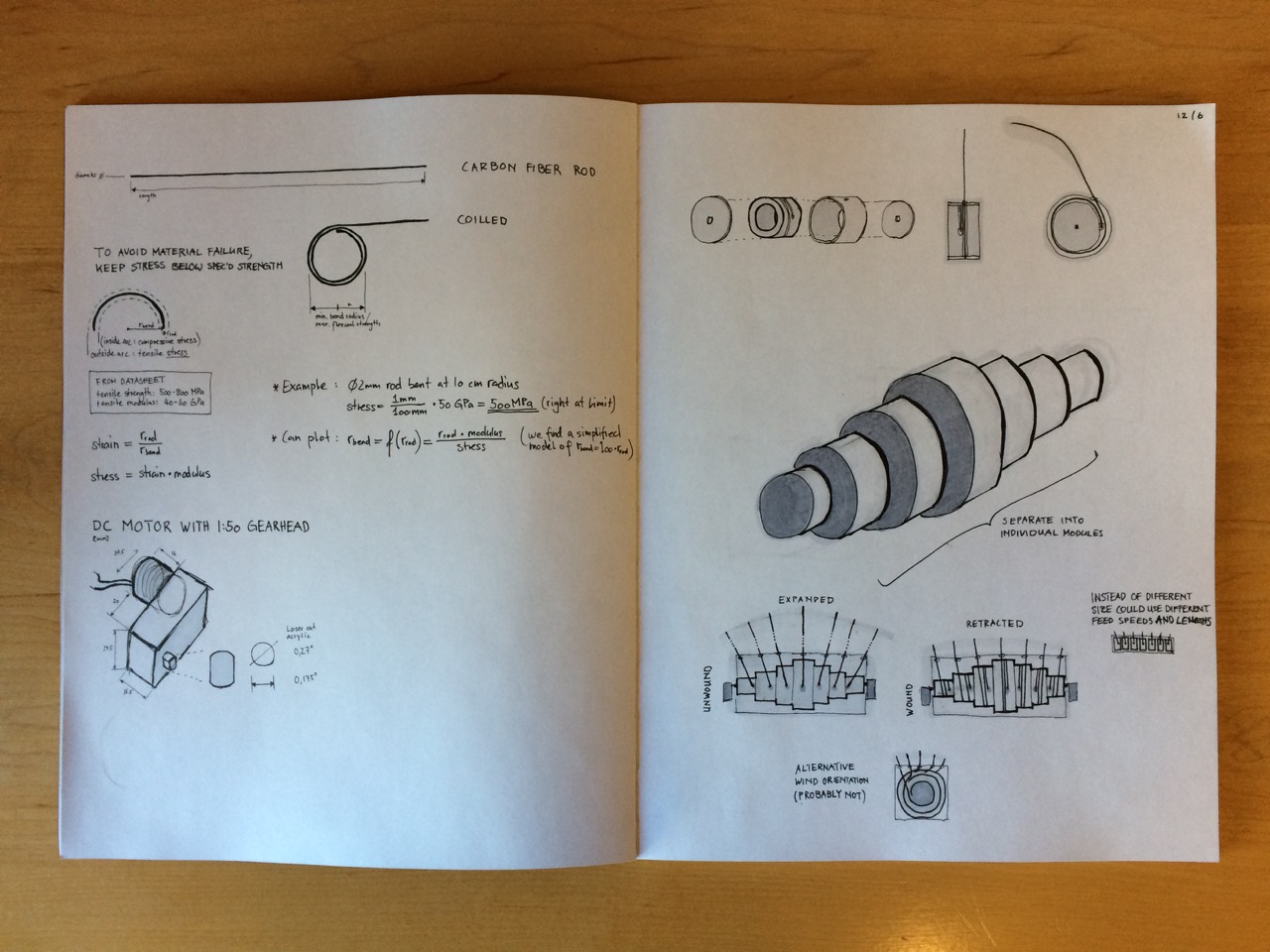
I modeled the spool and prototyped a few of the parts with a 3D printer. In doing so I confirmed that it would be a really cool mechanims but uncovered a lot of challenges in the field of mechanical engineering and too much of my project would have to focus on that as opposed to integration of other skills. A few challenges to solve:
- What is the stopping/zeroing mechanism for the actuator?
- How do I keep the rod under tension on the spool?
- If I enclose the spool in a case, how will friction against it make the system behave?
- How are the modules connected and actuated? Does each have its own motor?
- How do I mount a circular case on the back of a screen?
I also started to get worried about the needed torque. Low RPM high torque in a small package without big gearing down is difficult. I was planning on using tiny motors with a 1:50 gear head.
New direction. After quick prototype assembly, enter production mode. Gotta keep moving and hit daily milestones.
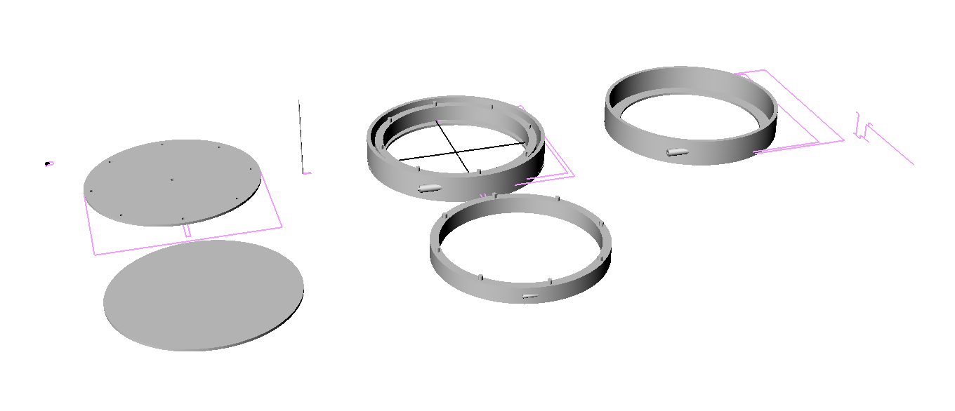
CNC Machining the Platform
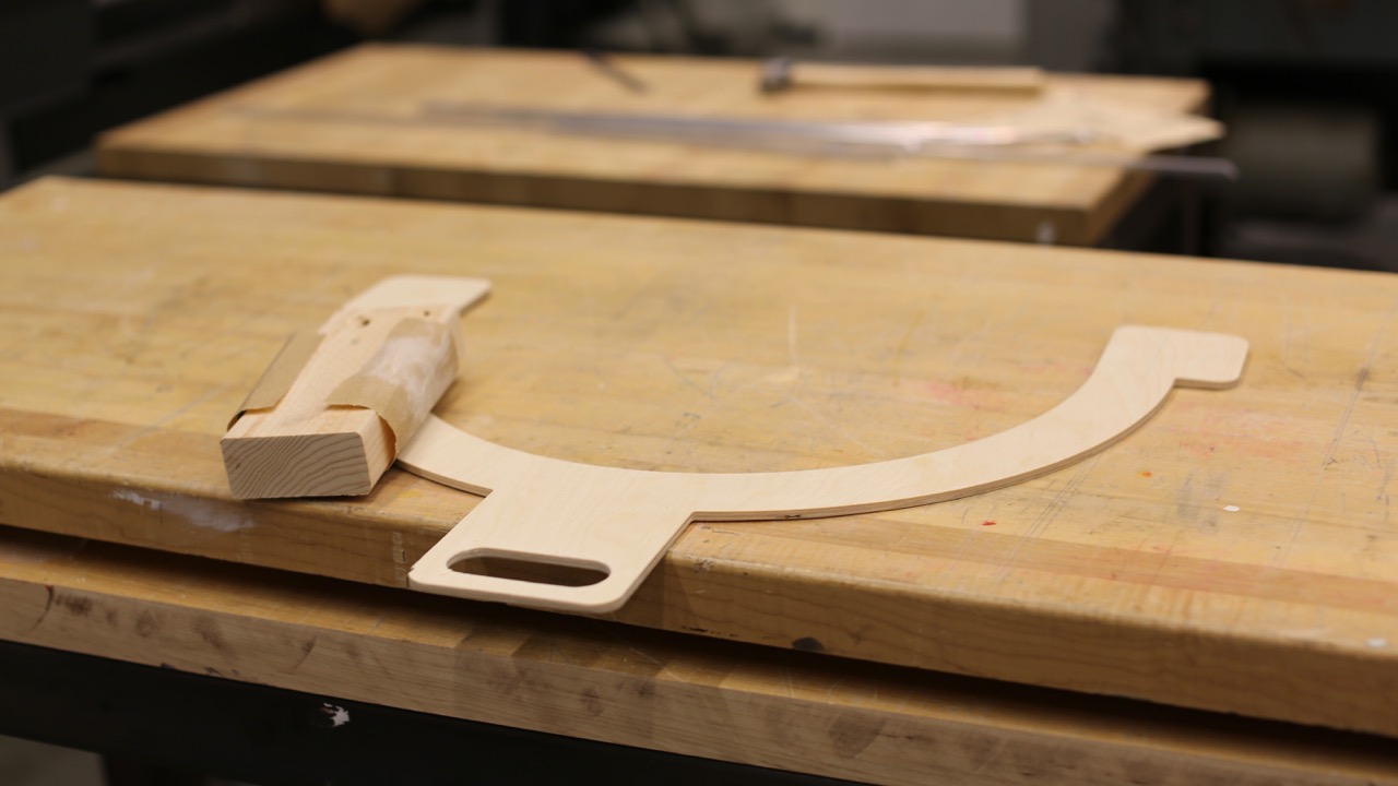
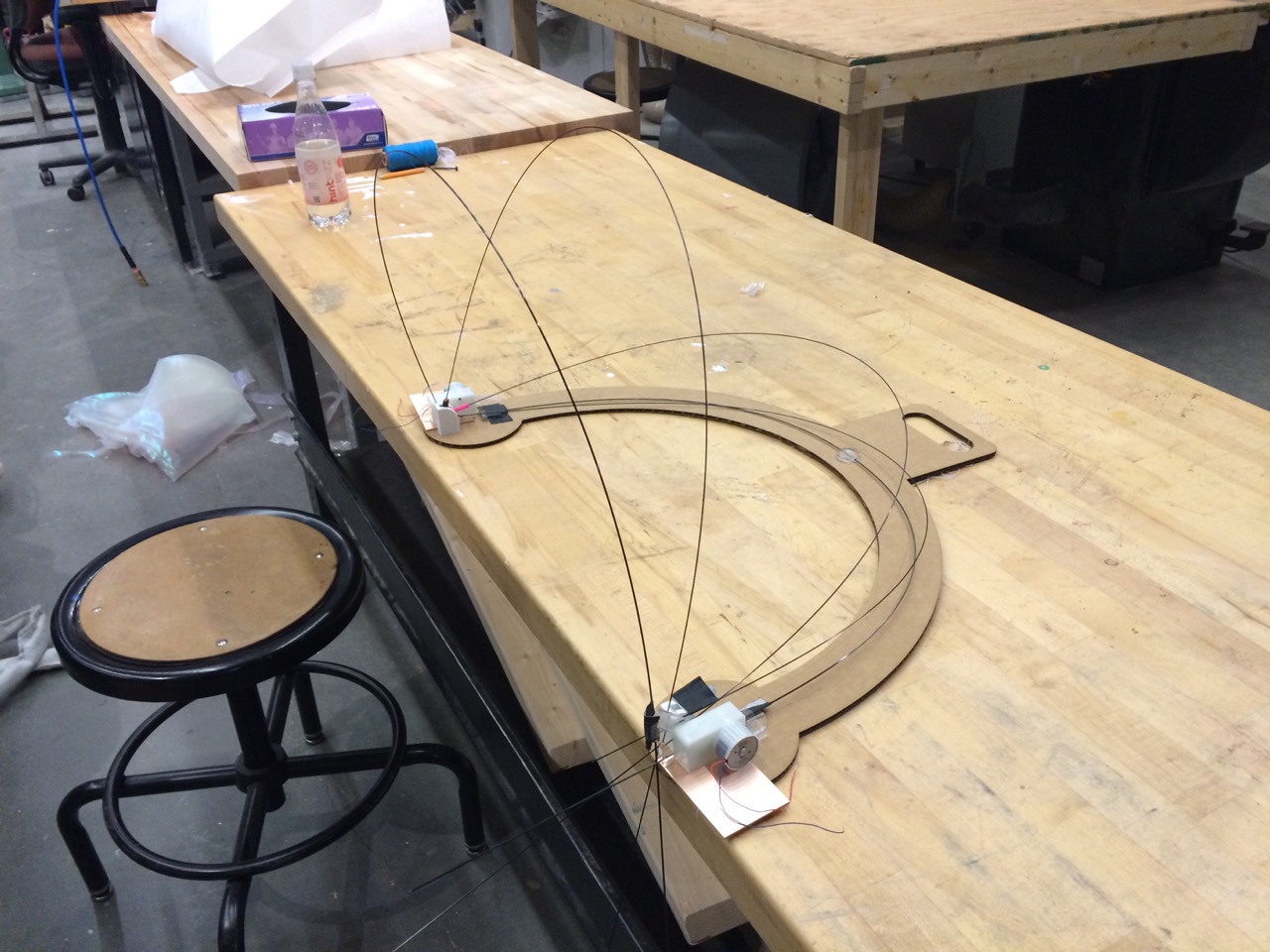
I did three rapid and integrated iterations of designing ⟷ evaluating a platform. The first iteration was a sketch in a notebook and a scissor-cut cardboard model. Then I moved to Rhino and modeled a second iteration which I laser-cut, again in cardboard. After evaluating that full-scale model with my other components I tweaked the design to increase space for housing the motor breakout boards on the sides and while walking around with the draft in my hand it occured to me that a handle would give the project a whole new dimension – the notion of a portable workspace. And so I spiraled my way to the final laser-cut model which I verified in a test assembly with all other components (or approximations thereof) I had so far. For me it was a powerful example of rapid prototyping and after locking into the emerged design it was time to take out the big tools and move to CNC milling the actual part.
“The CNC router is my favorite tool in the machine shop because it’s a good balance between terrifying and easy to use.” —Tom Lutz
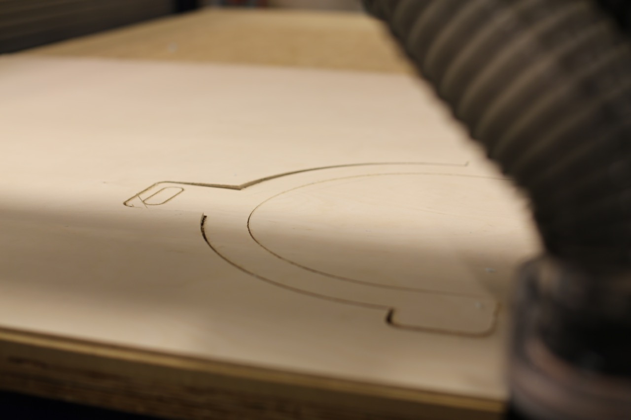
Laser Cutting the Rod Drive Shaft and Mounts
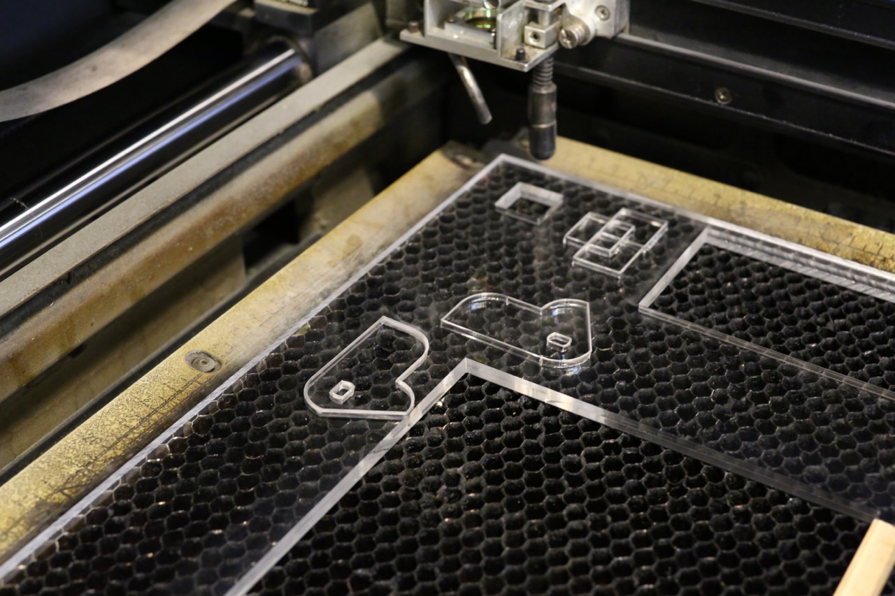
Rod Mount acrylic thickness: 3/16" = .177" = 4.5mm
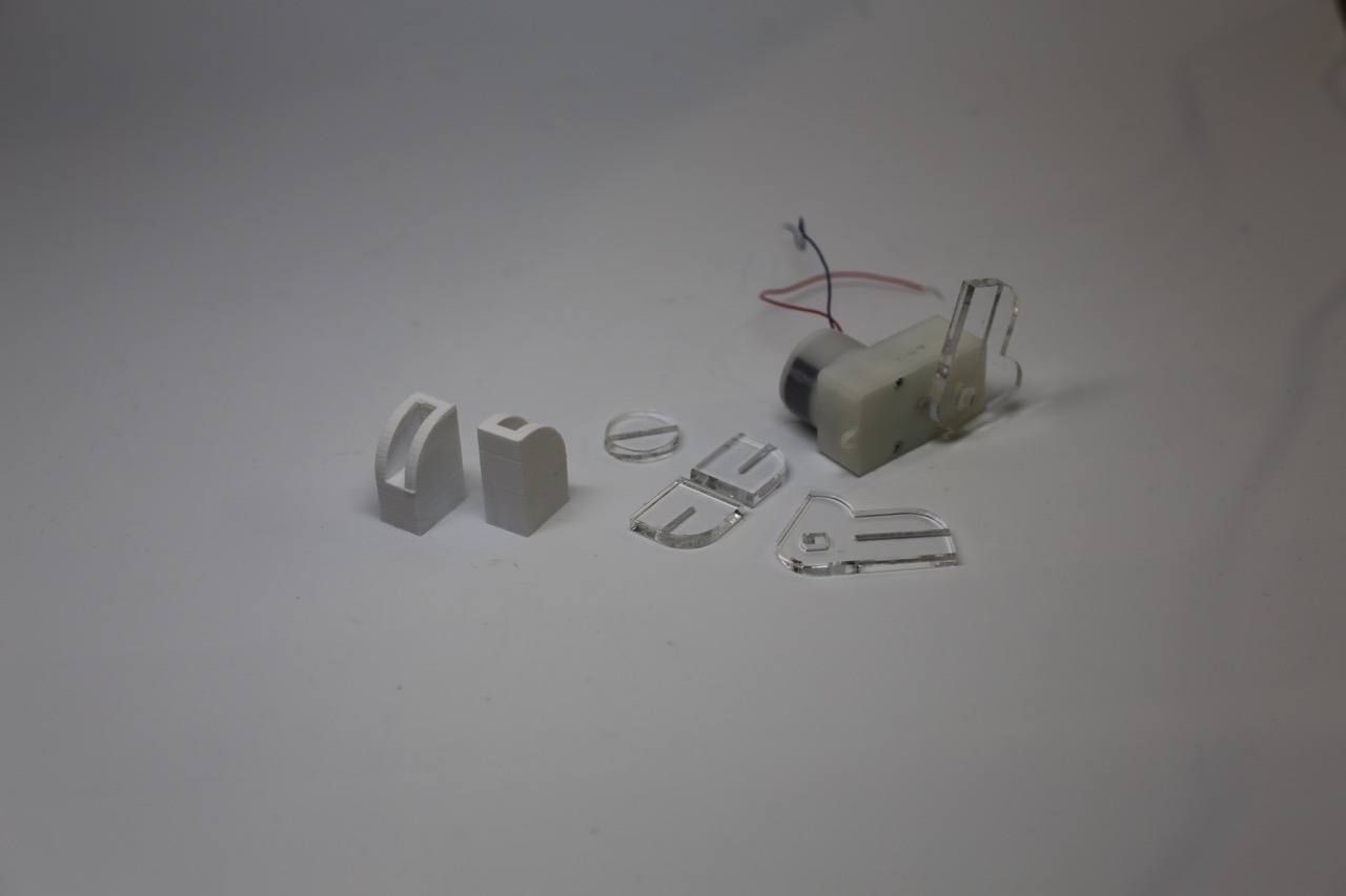
3D Printing the Rod Guide Rail
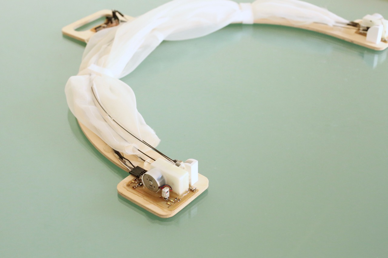
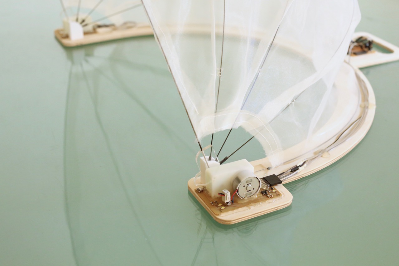
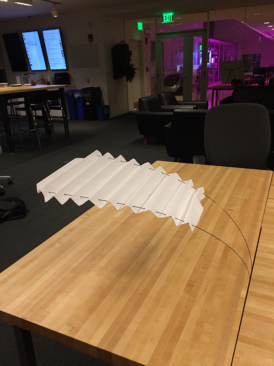
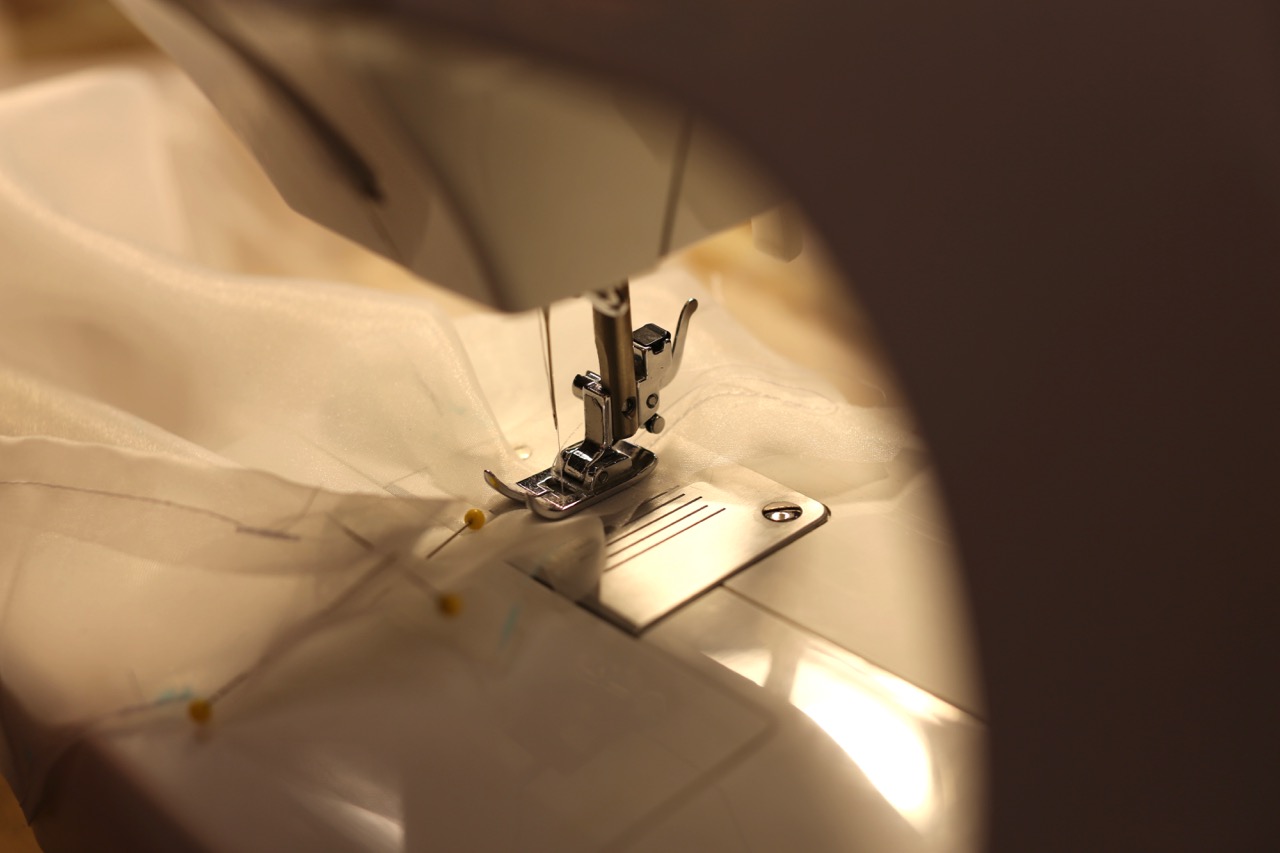
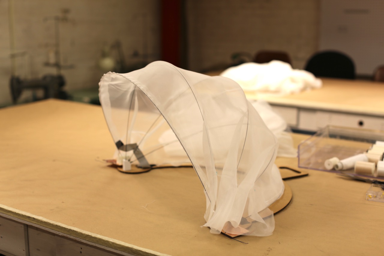
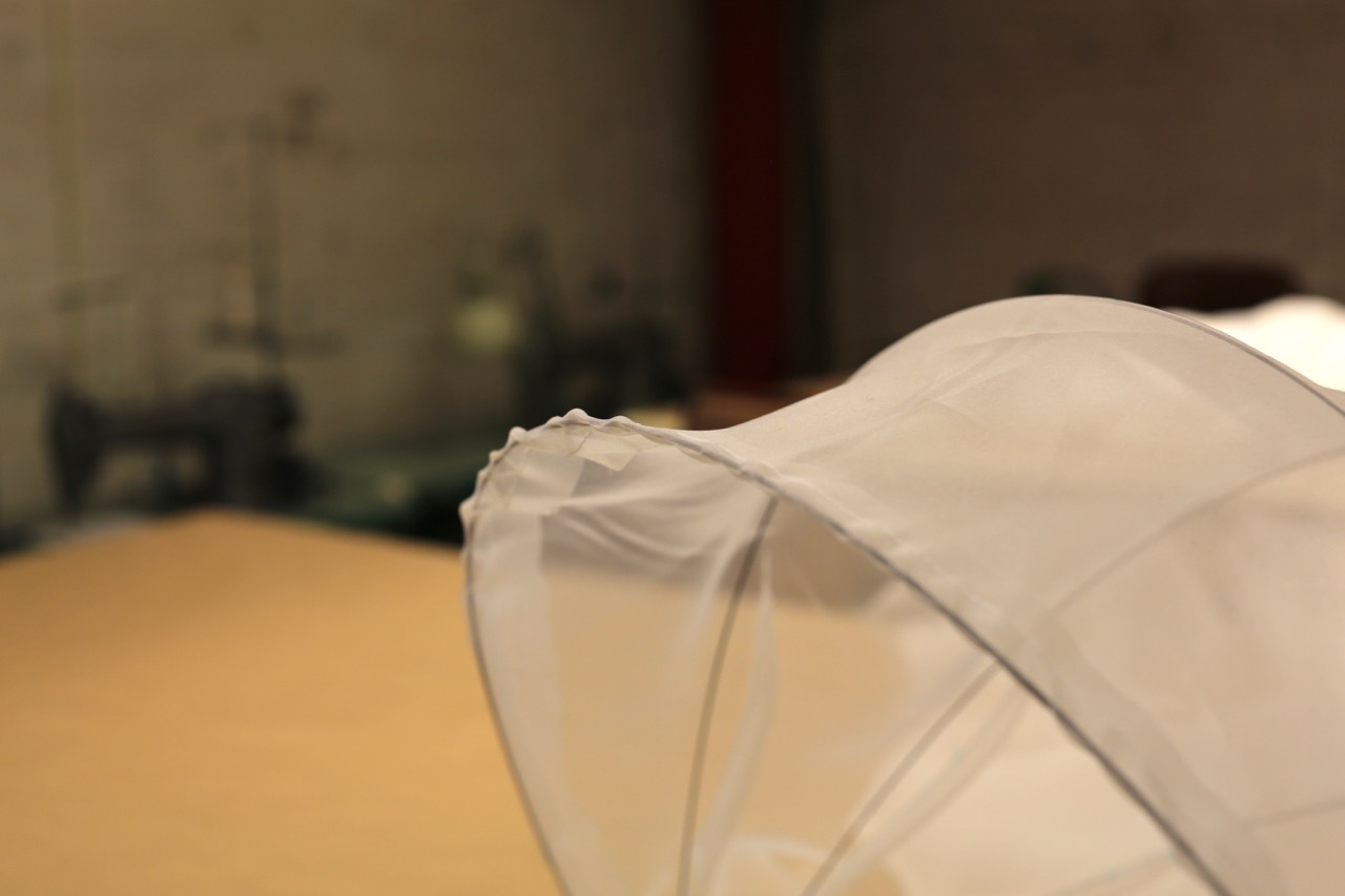
Sewing the Fabric
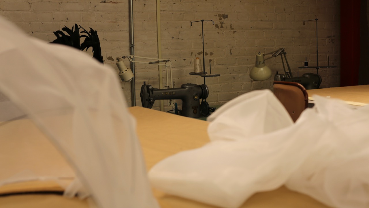
I considered light plastic, paper, and fabric as enclosing material. I chose fabric for its flexibility and nice texture. I went with an ultra light-weight fabric to avoid any issues with motor torque and for an airy look.
For the sewing I got help from my girlfriend. Drapping a curved shape that’s also flexible is a non-trivial task and I have little experience. As wearable technology become more important, it would be interesting to add a fabric recitation to the syllabus.
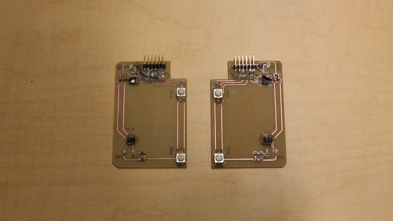
Motor Driver Breakout Boards
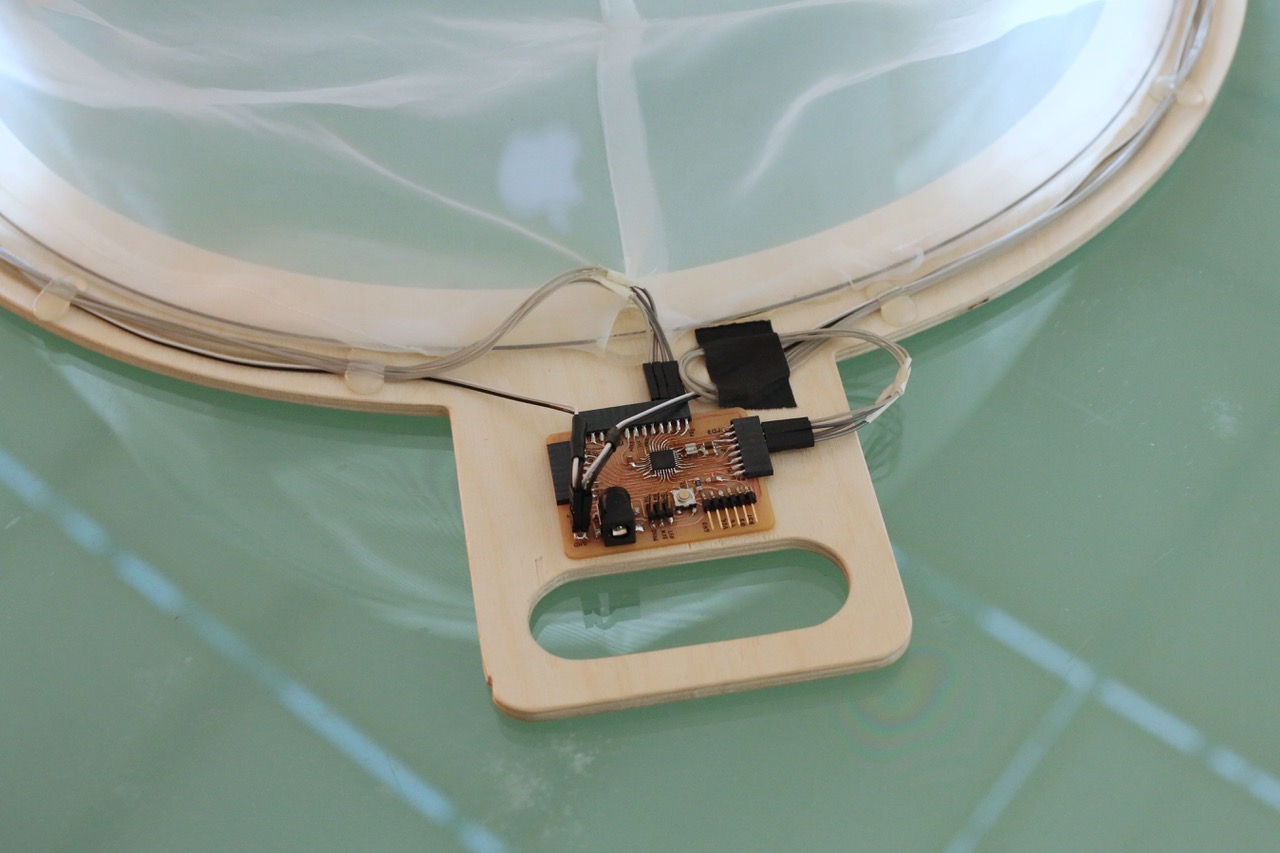
I debated whether I want to have MCUs on each motor driver daughter board and communicate with a central motherboard over a networking protocol or have one central mother board that drives the two motor boards. Advantages of the networking approach are that I could reduce the wires from six (+12V, GND, BTN1, BTN2, OUT1, OUT2) to four (+12V, GND, TX, RX) and that I potentially could have gotten away with a simple chip on the mother board such as the ATTiny44a. However, I’ve never done inter-MCU communication and it felt risky to do that for the first time during the final project. I also really wanted to make my own general purpose ATMega328p-based board, which would have plenty pins to drive everything centrally, and so I decided for that approach.
This allowed me to keep the two motor driver daughter boards electronically fairly simple.
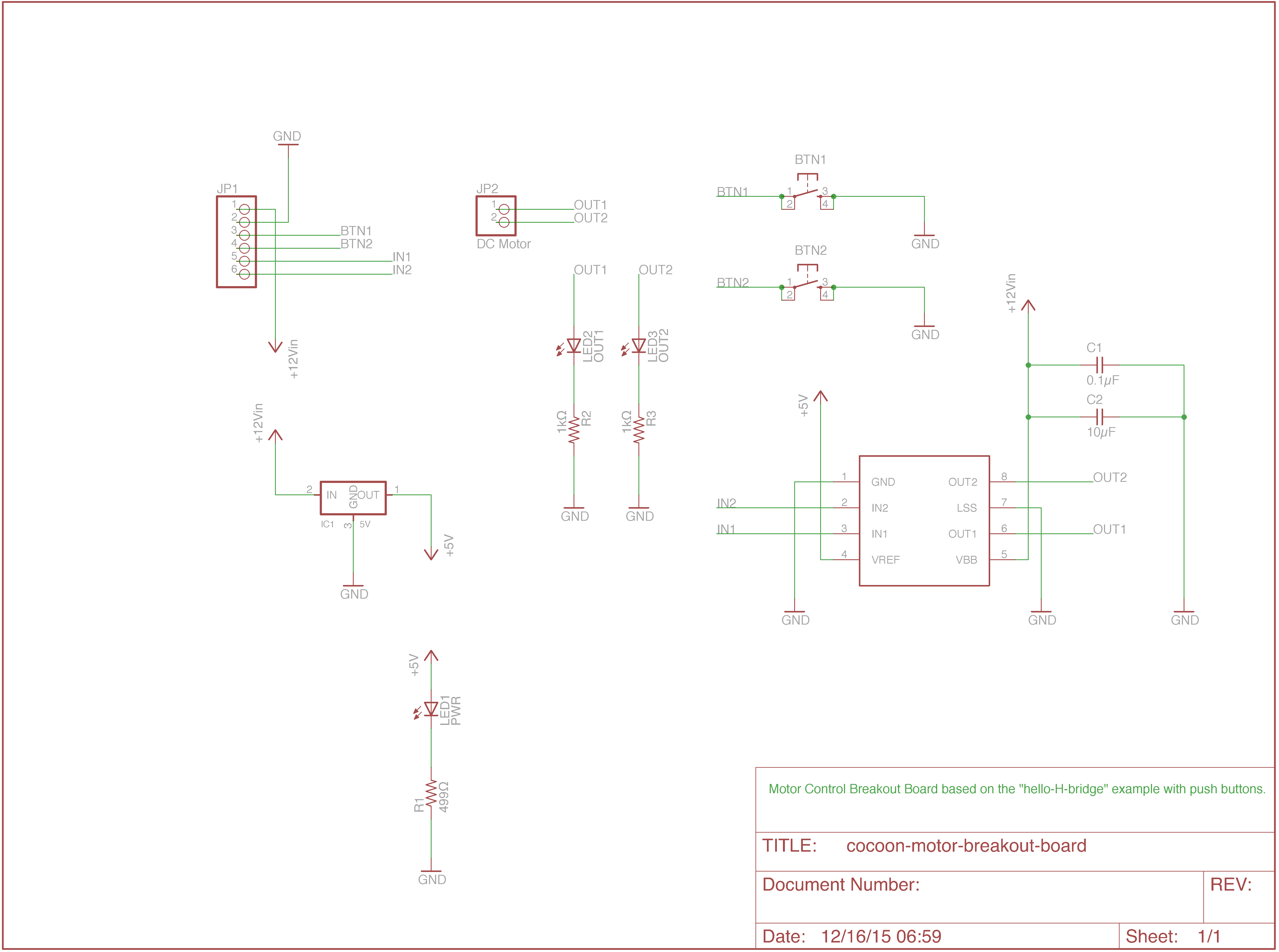
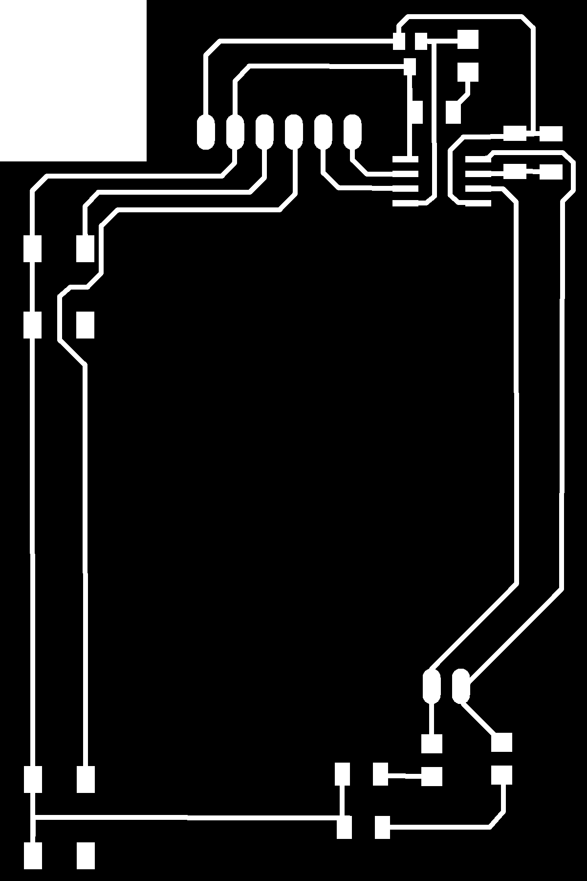
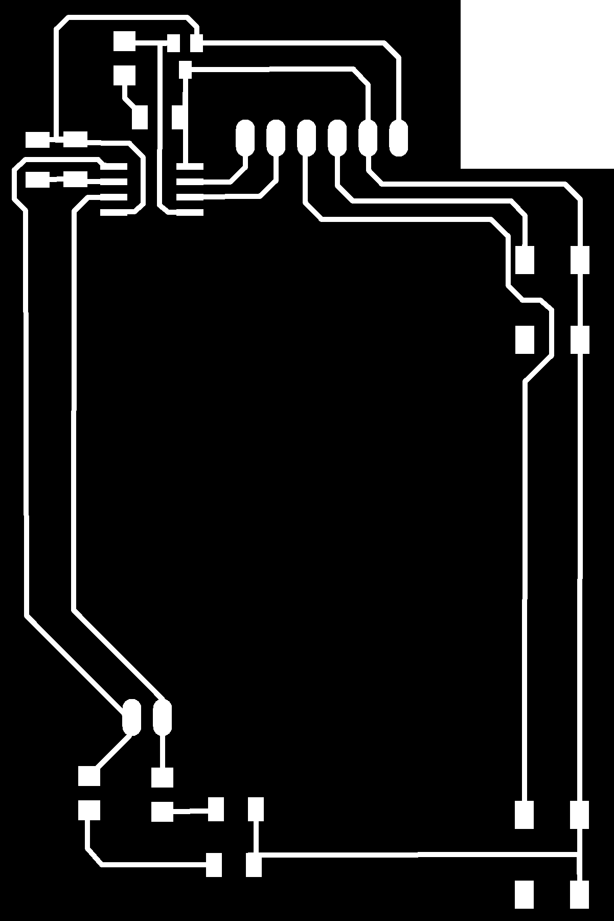
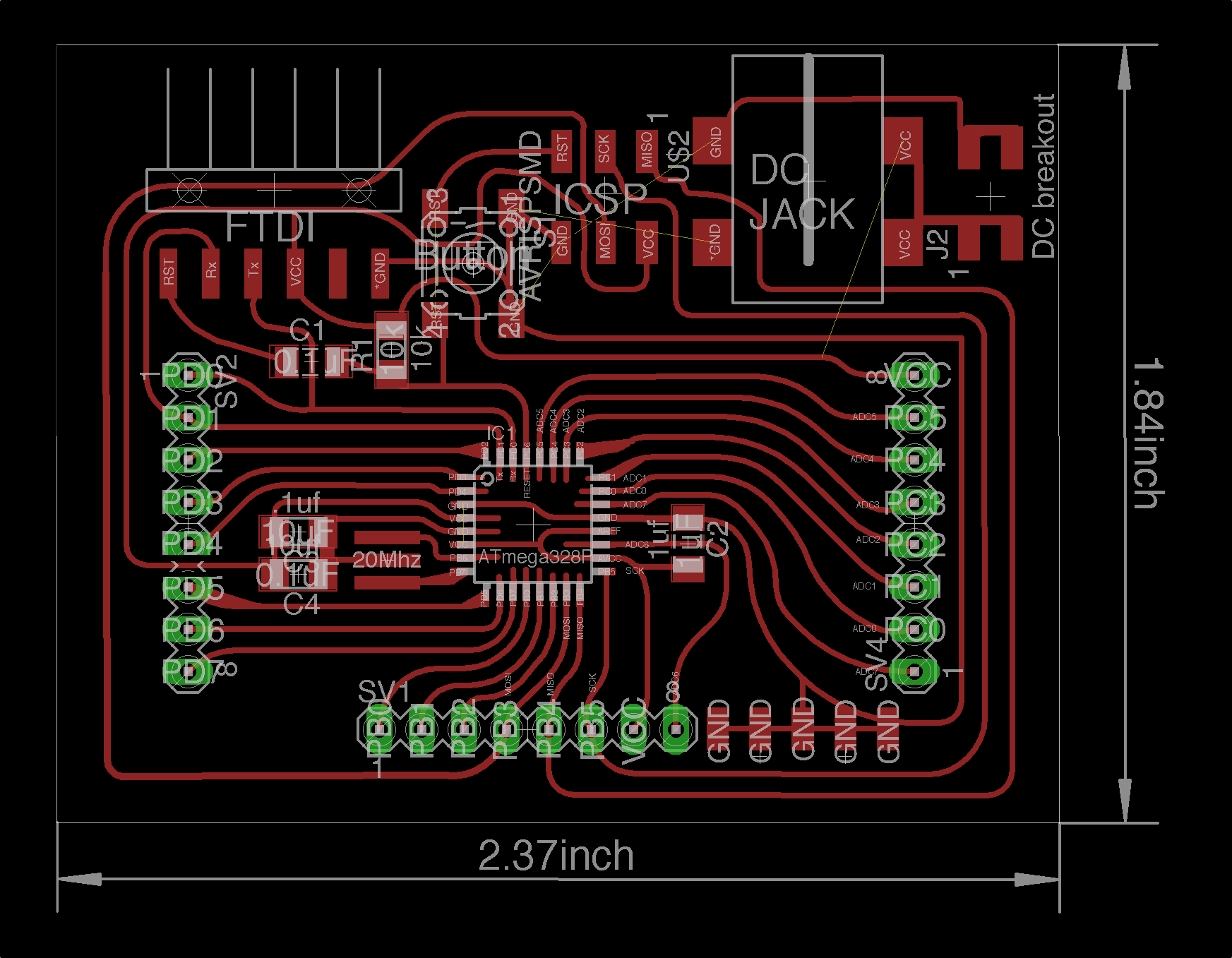
The board has both mechanical and electronical features. Mechanically it houses the DC motor with attached gear head as actuator (center), and the sensors (push buttons to the left) for the movement of the structure. Since the DC motors actuate the cocoon directly, this board is the mechanical base of the whole mechanism. The cutout to the top left accounts for the bottom most rod mount.
Electronically there’s the logic to the top left (5V regulator with power indication LED and H-Bridge to drive the motor) and the breakout for actuation (with LED indicators) on the bottom right. For communication, there’s a 6pin header (+12V, GND, BTN1, BTN2, OUT1, OUT2) to the top pointing towards the back of the structure where the coordinating motherboard will be housed.
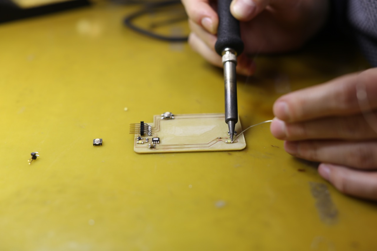
Integrating all structural, mechanical, sensory, and electronical constraints on this board with mm-precision while fitting on a standard 2x3" PCB stock was fun and challenging.
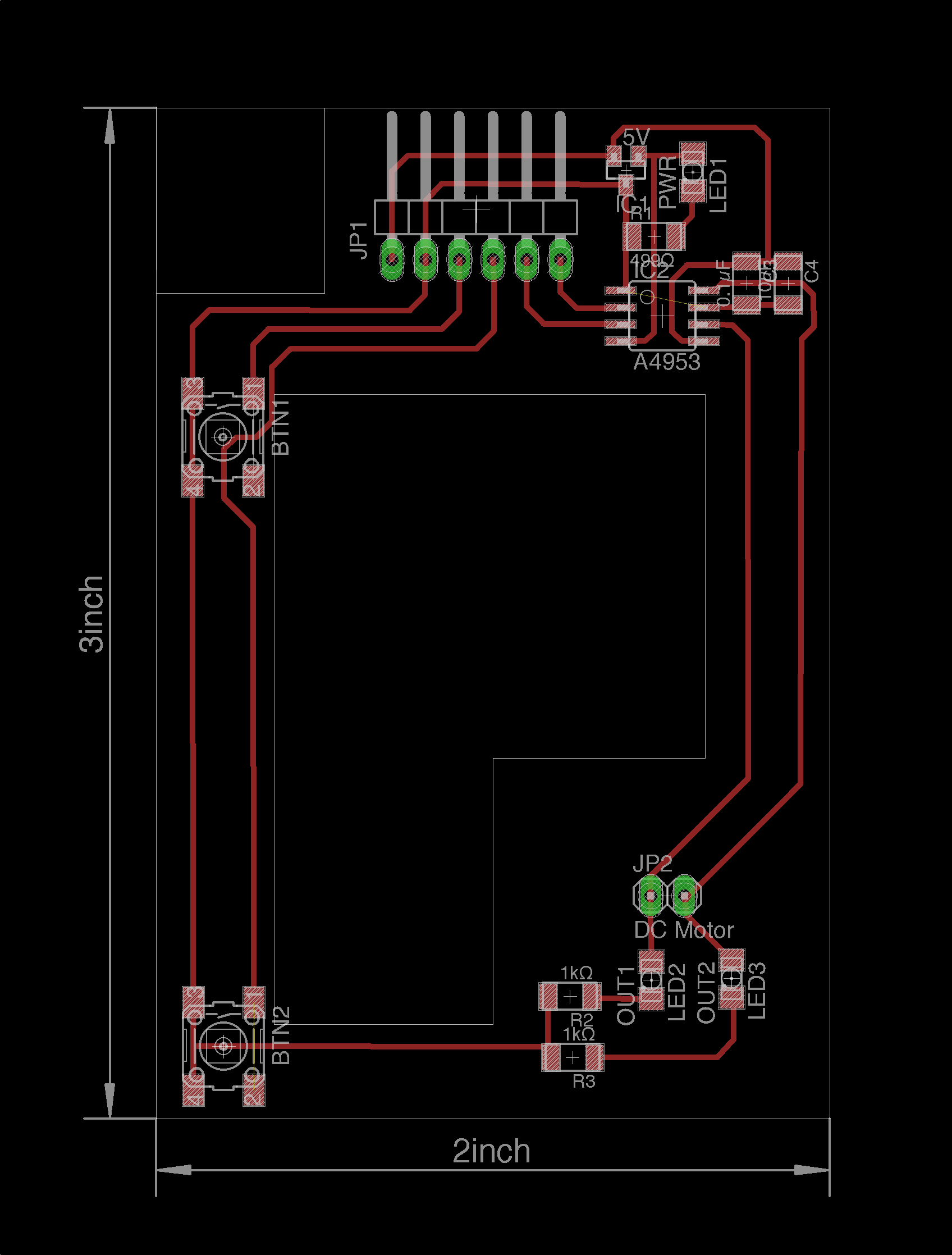
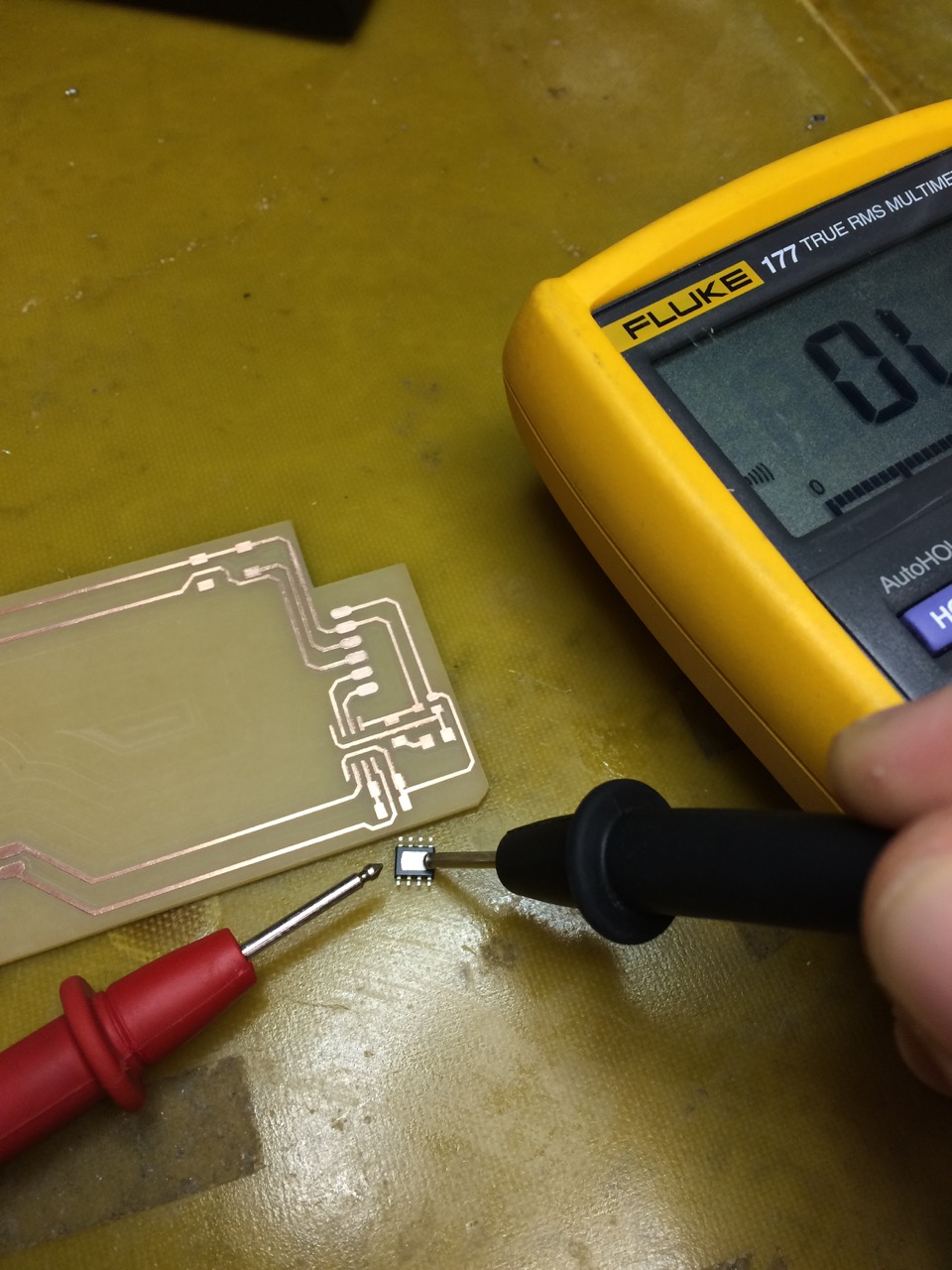
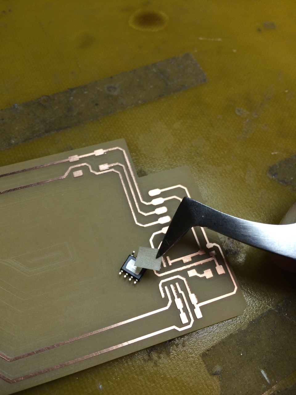
I avoided bridges in the board top right electronical logic area by neatly routing two traces under the H-bridge and compromising on an air wire I’d just solder onto the chip. But once I stuffed the board I noticed the big exposed thermal pad at bottom of the chip. That couldn’t be good and my fears got confirmed when it tested positively for conductivity. The easy fix was to build my own isolator. This will likely reduce its thermal properties but I wasn’t to worried about that as my load is expected to be fairly low. This is a good reminder to better study each components data sheet for intricate details before moving from schematic to routing.
In the spirit of rapid prototyping, here comes the hackiest hack known to mankind: once I fabricated and verified one of the boards I had to do a second one for the other side. They are identical other than their physical arrangement on the platform and I thought it would be clever to exploit the symmetry of my design and literally horizontally flip the traces and outline images. This way I’d avoid re-layouting and re-exporting. Physically, it already looks great, and …


… for this to work electronically I flipped all asymmetrical components (regulator, H-bridge) upside down, bent their pins down, and stuffed them in a “belly up”-orientation. For extra credit, now there’s no need to isolate the thermal pad of the second H-bridge anymore :-D
Spiral Development for System Integration
I successfully spiraled my way to a sound mechanical system by moving fast with cardboard prototypes first and testing the mechanics of the system component-wise. I wanted to continue with that approach and so started testing my boards immediately by driving them from an Arduino. I required
- 2 × 12V+GND breakout for the motors
- 4 × digital I/O pins for the buttons
- 4 × digital I/O pins with hardware PWM for the H-Bridges
- 2 × digital I/O pins+GND for two tiny push button breakout boards I made to simulate up/down signals from the computer
- TX/RX pins for serial communication to eventually test the communication with the computer
and for this the Uno board was the perfect prototyping platform.
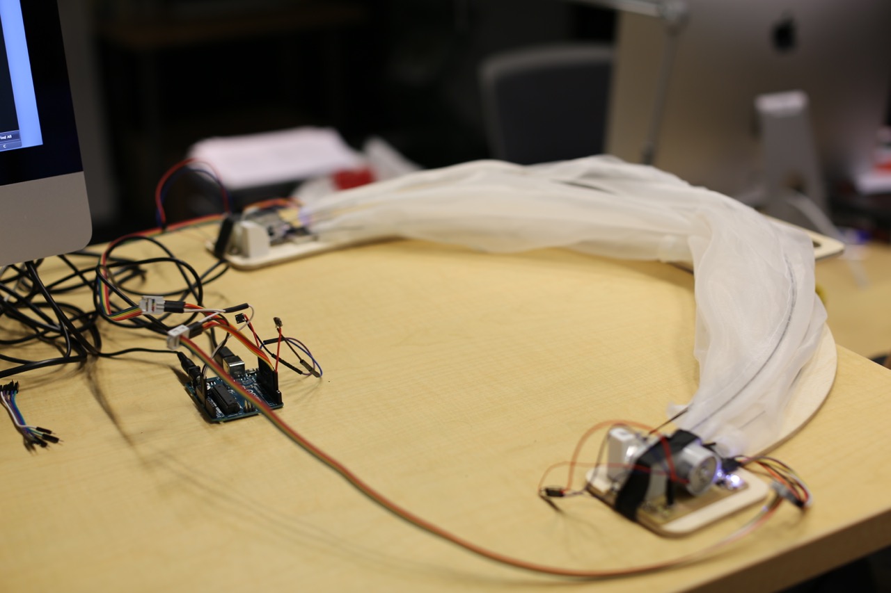
Once I verified my boards working, I could move on to software development. I could then later remove the hardware push buttons and rely on serial communication and also think about fabricating my own Schaaduino motherboard.
Embedded Programming

I did all my initial tests with the AVR toolchain I used for all my other projects. As I tested systems integration with an Arduino Uno I used their IDE. In general I like being in full control with the AVR toolchain better but the Arduino IDE came with three things I apprechiated. First, the SoftwareSerial package makes bit banging an AVR trivial. Second, using the chip’s hardware (i.e. non-blocking) PWM channels becomes as easy as writing analogWrite(pin, [0-255]). Third, the bundled Serial Monitor is handy.
During first coordinated actuation tests I found that the motors must have high RPM tolerances. I verified it by powering both motors with 12V from a lab power supply and noticing them spin at different speeds. I compared them with two more motors of the same model and confirmed that they’re all in the range of estimated +/- 20% off. So instead of swapping the motors out I fixed it with software by adding a PWM offset to one of the two motors. This means that the slower motor gets a longer PWM on-duration relative to the intended PWM speed.
In the integration process in general I really appreciated the debug LEDs I added to the boards.
Native macOS Menu Bar Application
Download source code cocoon_mac.zip
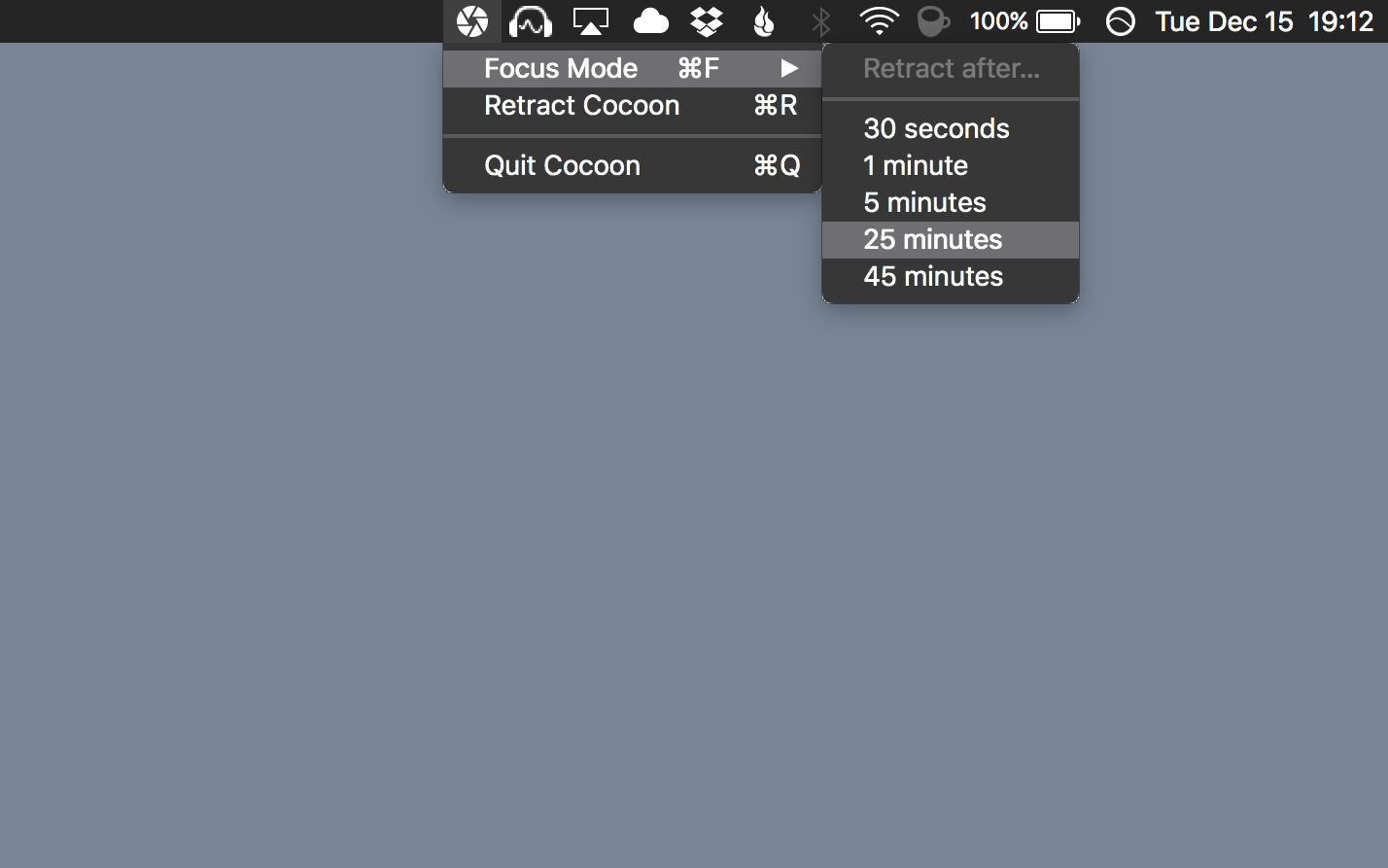
The host application with the user interface is a Cocoa app written in C and Objective-C communicating over serial.
Outlook
Foil that goes from translucent to opaque could be an interesting indicator of collaboration (translucent) to focus (opaque).