Output Devices
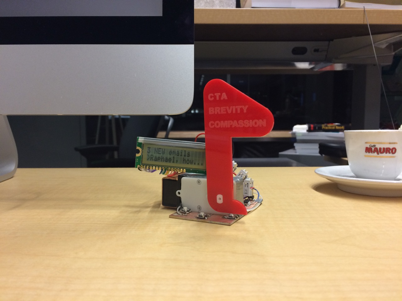
Mailbox Semaphore Flag
## lecture chip that drives LCD and how to program it is messy but once you use the abstraction routines it's easy to display text can synthesize video with a simple AVR chip and not much more hardware but complex software you want motors to go in both directions. use H bridge is a constellatin of N and P mosfet transistors to drive motor (turn left/right/brake). lots to know about different motors (DC with subvariants like servo, stepper https://en.wikipedia.org/wiki/H_bridge https://learn.adafruit.com/all-about-stepper-motors/driving-a-stepper two primary kinds of stepper motors 2 phases: odd/even unipoler 6 wires (also 5 wires because V can be combined) - no h-bridge needed, use 4 n-mosfets (current goes into the middle of the coil and pulled out on either sides) bipoler 4 wires - use two h-bridges, one for each phase more work to drive the bipoler stepper, BUT the current goes through the hole coil (not half the coil) which makes it twice as strong (tork), so they are commonly preferred. https://en.wikipedia.org/wiki/MOSFET transistors: - p-mosfet (Positive) sourcing from V - n-mosfet (Negative) sourcing from GND microcode -> h bridges easier: motor control chip. includes logic to run h bridges/stepper e.g. http://www.allegromicro.com/en/Products/Motor-Driver-And-Interface-ICs/Bipolar-Stepper-Motor-Drivers/A4979.aspx shape memory: http://fab.cba.mit.edu/classes/863.10/people/jie.qi/jieweek10.html - great to embed motion - fuzzy to learn to use and to control
It matters whether the motor (or any load) is on the V side of the switching transistor or the GND side. If it was on the high side we’d have to switch with a pMOSFET, which is harder to drive from our logic +5V. If it’s on the low side we simply switch with an nMOSFET, which is also more efficient. This is also why steppers typically only have one V wire and the switched wires are connected to GND.
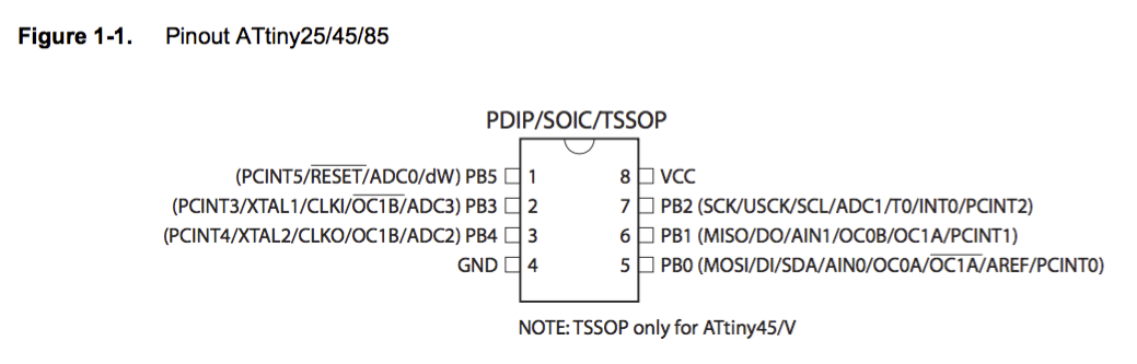
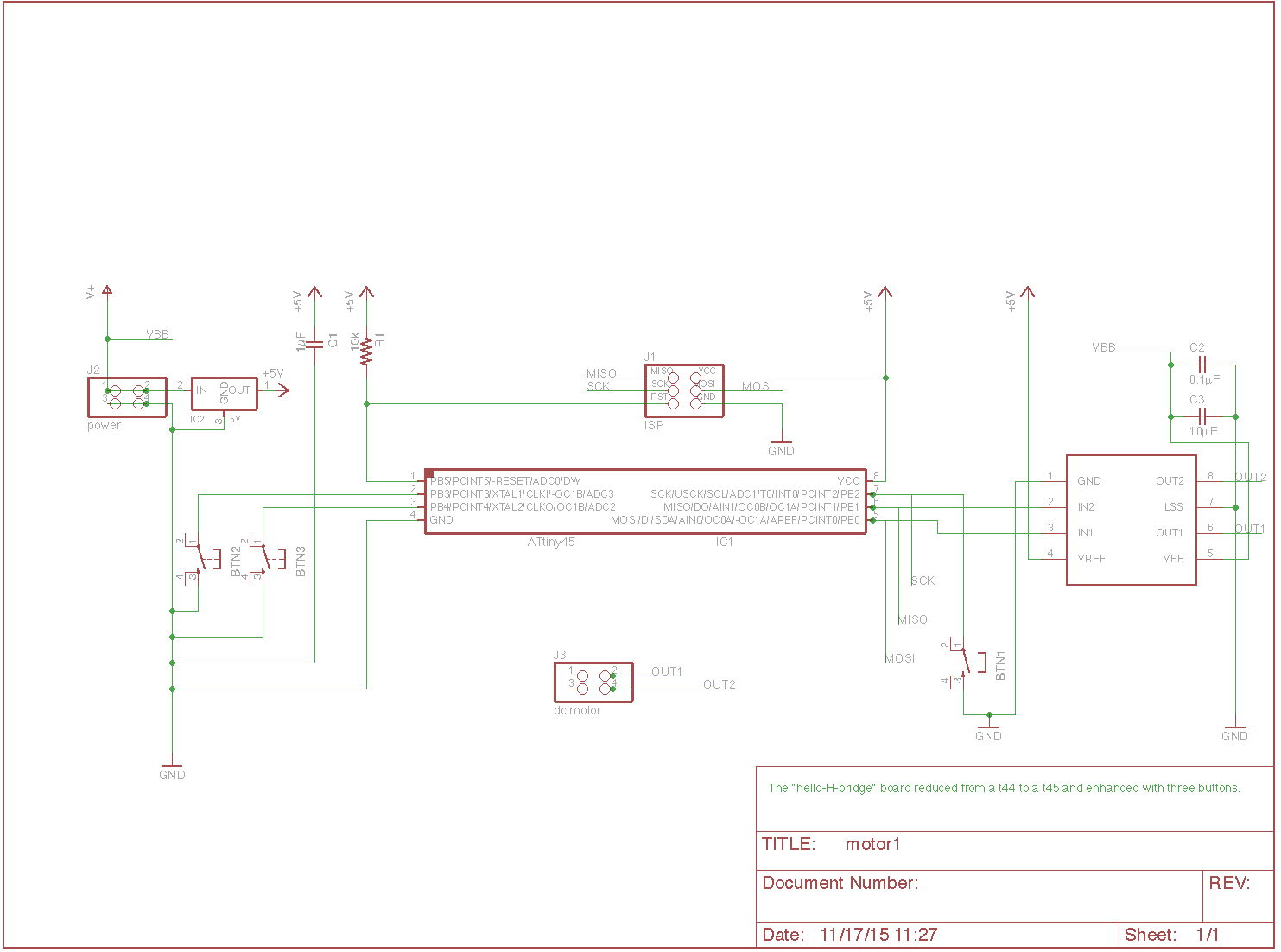
flyback diodes: shorts the transient back into the high side of the power supply not needed for small motors transistors often have a small one built-in to protect themselves The "hello-H-bridge" board reduced from a t44 to a t45 and enhanced with three buttons. // Hardware: // Based on Neil Gershenfeld's board: http://academy.cba.mit.edu/classes/output_devices/H-bridge/hello.H-bridge.44.png // With my redesign and enhancements: http://fab.cba.mit.edu/classes/863.15/section.CBA/people/Schaad/week9-output-devices.html #define BTN1 (1 << PB2) // left (pin 7) #define BTN2 (1 << PB3) // center (pin 2) #define BTN3 (1 << PB4) // right (pin 3) #define MOTORCCW (1 << PB0) // IN1 (pin 5) #define MOTORCW (1 << PB1) // IN2 (pin 6)- supply1/+5V
- supply1/gnd
- fab/attiny45si (part ATTINY45V-10SU-ND)
- fab/a4953-h-bridge-motor-driver (part 620-1428-1-ND)
- fab/regulatorsot23 (part LM3480IM3-5.0/NOPBCT-ND)
- fab/6mm_switch6mm_switch
- fab/res-us1206fab
- fab/cap-unpolarizedfab
- fab/avrispsmd
- fab/pinhd-2x2-smd

Recitation Hardware Design
- Mechanical design (making): materials, parts, mechanisms
- Machine design (automating): modularity, control loop theory, toolpath planning
- Robot design: universal robotic arms
Outlook
I’d like to explore Charlieplexing (named after its inventor Charlie) to drive lots of LEDs yet save pins on the MCU. Initially you’d think n pins drive n LEDs. With row/column scanning this can be increased to 2×n LEDs. Charlieplexing increases this further to n×(n-1) by leveraging the fact that PINs can be configured in three states (as input/disabled [X], output low [0], and high [1]) and LEDs conduct in only one direction. Jonathan Bobrow links to further resources on his embedded programming week page and there’s the “LED array” example board on the class page.
Also interesting are Adafruit’s NeoPixels (China fab banggood.com purchase link), which are RGB LEDs that integrate a small MCU each. Long strips or big arrays can then be driven from a single pin using a networking protocol.