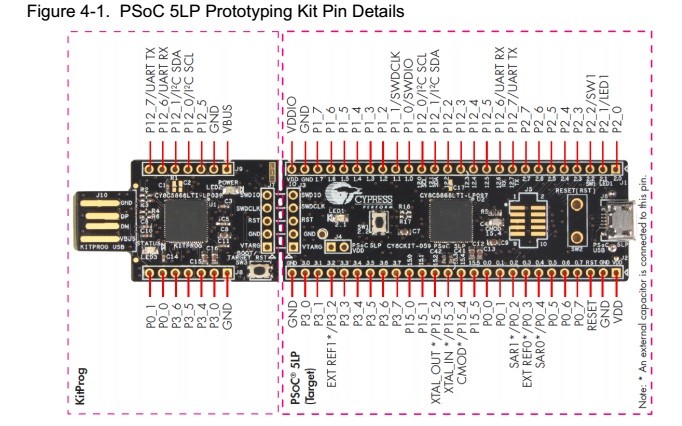
For this week's assignment I chose to dust off Cypress's PSoC line - I haven't made much use of them since the PSoC 1 days, and PSoC 4s look interesting.
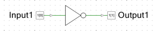
One of Neil's favorite games is the "Software Ring Oscillator Test": Electrically tie an input pin to an output pin, and in software send the inverse of the input to the output as quickly as possible. This is a simple test of the delays inherent in and between the I/O ring and the core. The PSoC has a some programmable logic, so I decided to run a hardware version of the same test.
Open the "Schematic" (.cysch) portion of your PSoC program. Create one of each of the following components:
You can give these pins more useful names now.
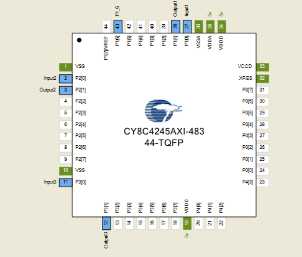
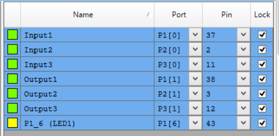
Open the "Design" (.cydwr) and open the pin map. Assign the Input and Output Pins.
I prefer this view when layout is important.
I prefer this view when port identity is important. Both are equivalent.
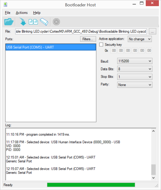
You can load code in two ways. The first one is through a Boot Loader. This lets you program boards with very little support circuitry, but you lose the ability to debug. This is the method supported by the cheapest PSoC dev kit, the CY8CKIT-049 ($3.99)
Add the "System -> Bootloadable" element to your .cysch. This preps the image so that it can be placed correctly in memory by the bootloader. Build the project as normal, and then use the Tools -> Bootloader Host to push the image in.
Single Wire Debug is the programming method used by the more expensive CY8CKIT-059 ( $9.98 )
The other available method requires a full programmer, but fortunately these come with the development sticks. The left portion snaps off to become a stand-alone SWD () programmer.
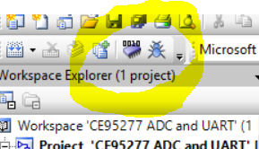
Once this is connected, program and debug with these buttons:
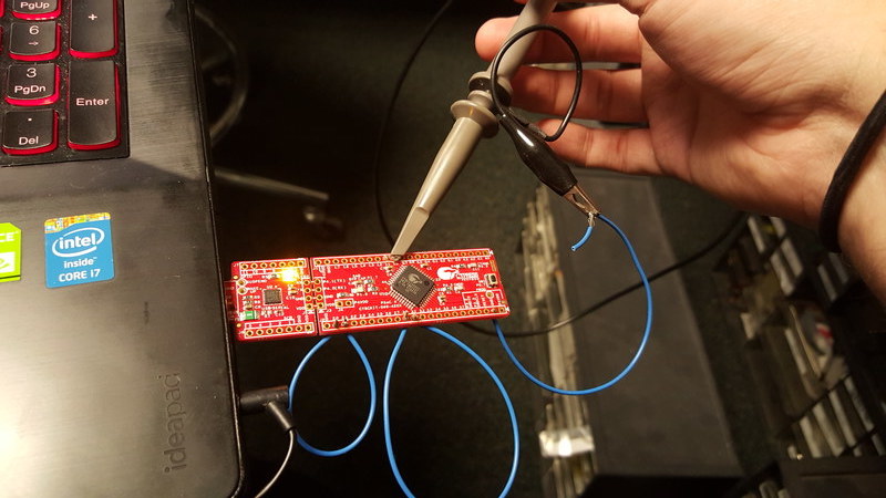
Attach an oscilloscope probe to the pins in the oscillator.
Sam's previous record was a little north of 6MHz, which is already 50% faster than the next fastest contender. I knew I had to cheat to win, and my first attempt came up at 16MHz!
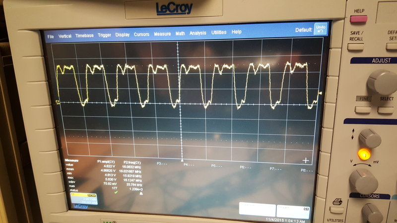
With a bit more tweaking, 26.7MHz! This is the equivalent of 53.4M samples per second, and the part is clocked at 48MHz. I'm getting 1.1 samples per clock cycle…
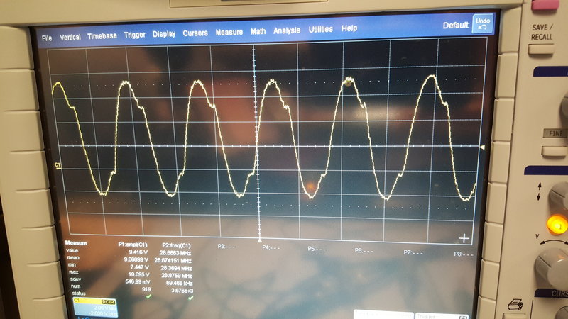
This is possible because the "computation" done doesn't involve the core at all. I turned off all synchronization to that clock to achieve these speeds.
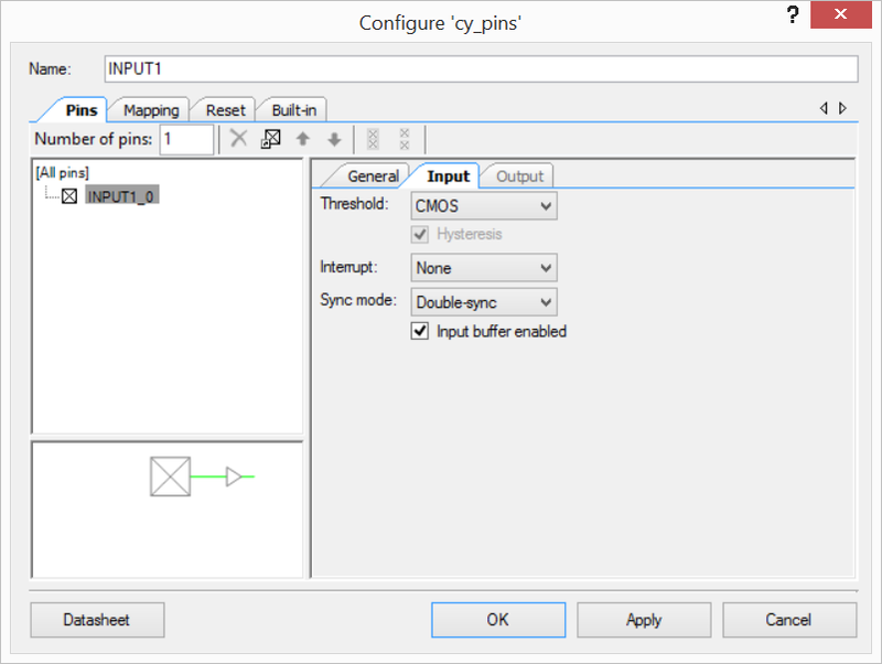
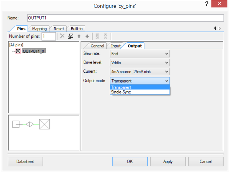
In the pin configuration, the "Input" and "Output" tabs give you control over the pin's physical behavior and its basest logic interfacing. This is how you can adjust drive strengths, thresholds, and interrupt behaviors. It also allows you to change how it synchronizes with the outside world.
By default there are two stages of synchronization on all inputs and one stage of synchronization on all outputs. This protects the rest of the chip in the case that an external and internal edge coincide too closely.
Hardware is faster than software, especially when you turn off the safeties.