For my final project, I have made a light-sensitive curtain driver which closes curtains when it is dark and opens them with high light intensity.
Brief description:
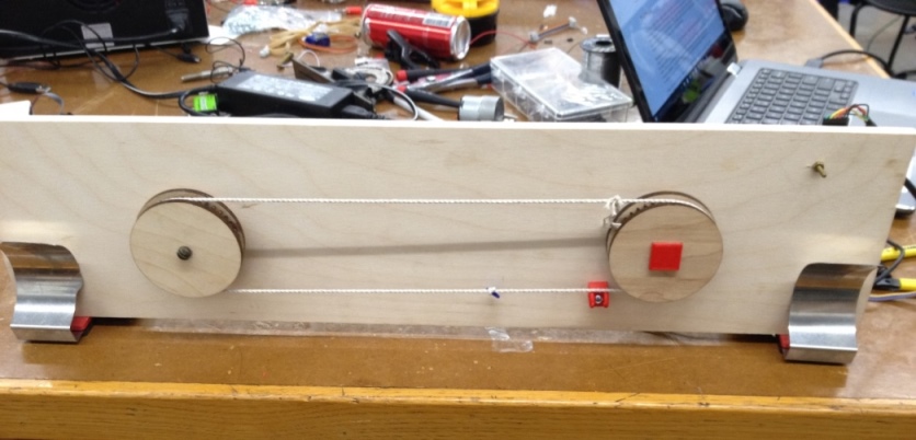
The curtain driver system consists of a light sensor whose input a microcontroller uses to decide when to drive a motor.
When the motor turns, it drives gears whose motion controls the position of a curtain rail.
The micro-controller checks for changes in ambient light intensity. It responds to changes around a pre-defined threshhold.
I describe below the fabrication of the system, including electronic and mechanical design and fabrication and assembly.
Electronics Design:
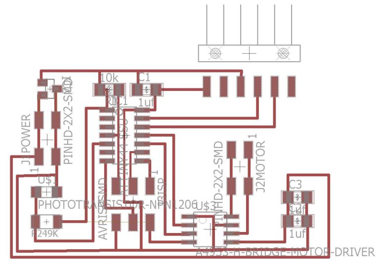
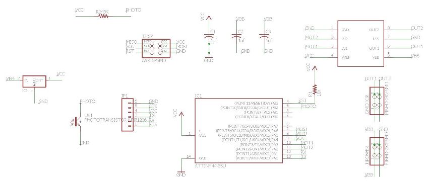
I based my board design off the sample boards available on the Fab website. I integrated the light sensor and DC motor boards.
At first, I did a poor job integrating the two circit systems and ran into the problem of the 5V regulator smoking as soon as the ftdi cable is plugged in.
The reason for this is that the ftdi was trying to push current through the regulator in the opposite direction to what the regulator is designed for.
I worked around this problem by cutting off power supply from the ftdi.
Voltage Drop across H-bridge:
I also learned as I worked that the H-bridge has a very high voltage drop across it.
When I provided the board with the standard 5V of power, the motor was not able to turn.
Measuring the voltage across the motor pins, I would register only up to 1V supply to the motor pins.
Cranking the voltage up to 12V solved this problem, allowing me to read 6V on the motor pins.
Attiny Analog Pin:
When I first made the board, I was not able to receive serial input from the light sensor pin, even though I could see by testing with
a multimeter that the light sensor registered different voltages across it depending on ambient light intensity.
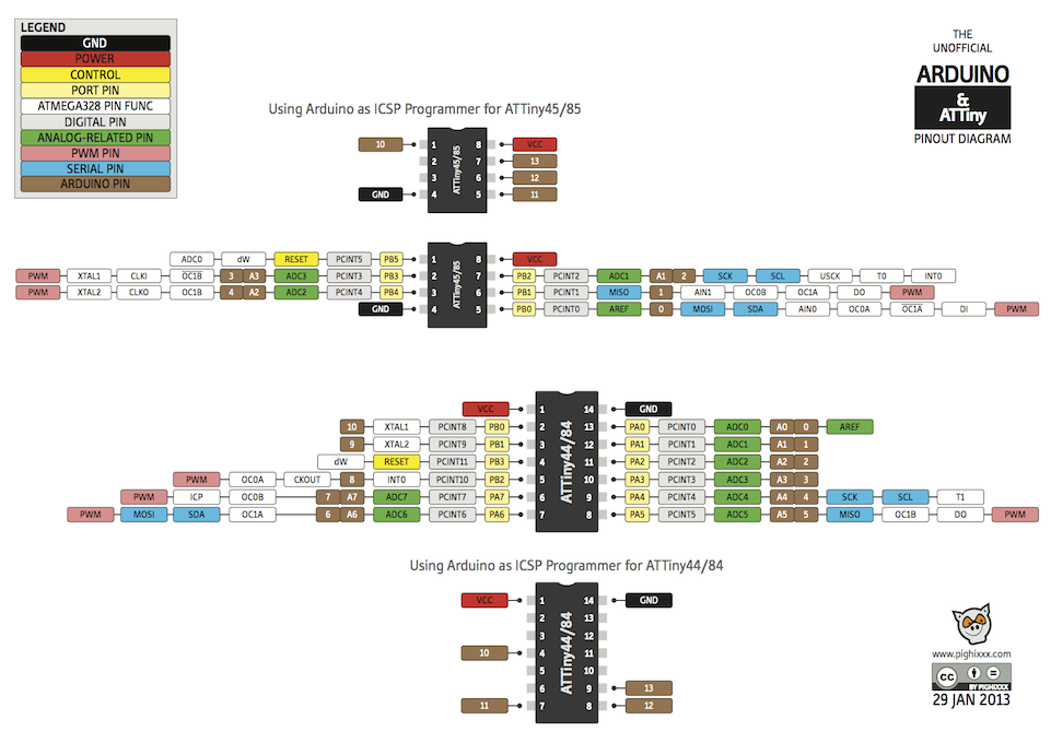
This was because I was trying to analog read the light sensor pin in Arduino, while the pin itself is not an Analog pin.
To correct for this, I disconnected the initial pin by cutting the trace and jumped the light sensor to one of the Attiny's analog pins.
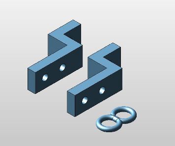
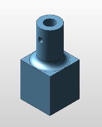
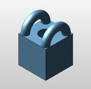
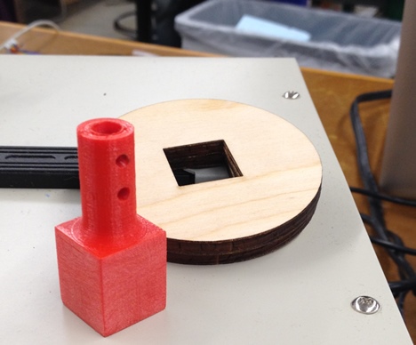
3D Modeling:
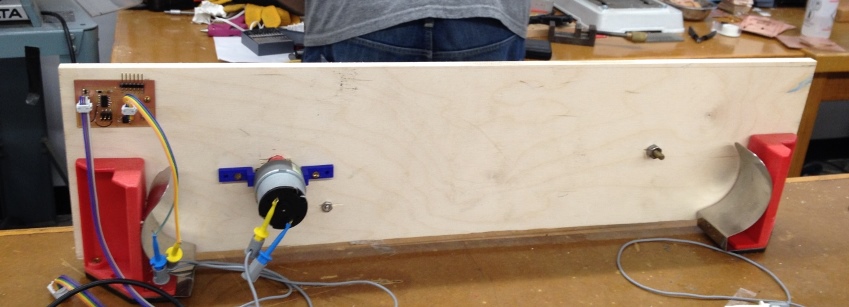
Several components of the system were 3D modeled and printed, including the gears, an adapter to mount the gears to the motor,
the motor mount, and the mounts for the curtain.
I did all my modeling in KeyCreator.
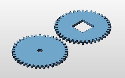
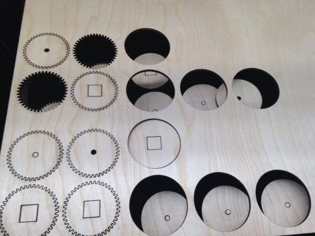
Laser Cutting:
The gears were lasercut out of wood 3/16th thick wood. I was not aware before working on this project that you could lasercut wood without running the risk of burning it.
I exported 2-Dimensional projections of the gears to Corel Draw (software the speaks with the laser cutter) before calculatinig cutting paths.
The speed and intensity had to be exactly right to get the wood to cut all the way through without charring too badly on the edges.
After several trials, I used the following settings:
-Laser Intensity: 100%
-Laser Speed: 2%
I found that a speed of 1% charred the wood too much, giving it a burned appearance, while 3% did not cut all the way through.
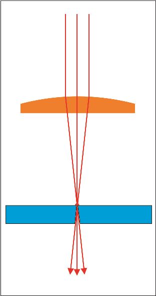
One interesting thing I learned about the lasercutter is that it does not cut vertically down as I had initially imagined. The cutter cuts by definition at an angle since it focuses a beam down at a focal point, which in this case was the top of the material. Below this focal point, it cuts at an angle. Here is a good image I found here that demonstrates this.
3D Printing:
I 3D Printed most of the solid pieces for the gear system on an Ultimaker 2.
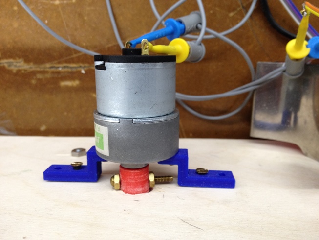
I was initially concerned about integrity of the pieces since many of them are load-bearing, including the motor mount and the gear to motor adapter.
The pieces have held up well however, and have been able to bear the loads gracefully. I used a 30% fill density for most of them, and a shell thickness of 1.2mm.
A note on this is that shell thickness is most accurate when it is set to be a multiple of the nozzle size. In this case, the nozzle is 0.4mm thick.

Programming
The program I wrote checks for changes in ambient light below or above a specific threshold and turns the motor on either to close the curtains or open them.
Currently, there are only two possible positions for the curtains: open nor closed. With time, I hope to develop the program further to include:
-Several positions, scaled to the light intensity.
-User input, which would allow a user to set preffered time or light intensity for their curtains closing.
Below is a copy of my code:
#includeSoftwareSerial mySerial(0, 1); // RX, TX int motorDirA = 2; int motorDirB = 3; int photoPin = 7; int sensorValue = 0; //boolean day = true; //boolean daybefore = false; boolean daybefore = true; void setup() { // initialize serial communication at 9600 bits per second: mySerial.begin(9600); pinMode(motorDirA, OUTPUT); pinMode(motorDirB, OUTPUT); pinMode(photoPin, INPUT); } void loop() { sensorValue = analogRead(A7); mySerial.print("Photo Val: "); mySerial.println(sensorValue); boolean day; if (sensorValue > 500) { day = false; } else { day = true; } if (day != daybefore) { if (day == true) { digitalWrite(motorDirB, HIGH); digitalWrite(motorDirA, LOW); delay(1000); digitalWrite(motorDirB, LOW); } else { digitalWrite(motorDirB, LOW); digitalWrite(motorDirA, HIGH); delay(1000); digitalWrite(motorDirA, LOW); } } else { digitalWrite(motorDirB, LOW); digitalWrite(motorDirA, LOW); } daybefore = day; }
Motor Speed
Arduino has a very nifty method for pulse width modulating (PWMing), but I couldn't use this because of my electronics design.
PWMing in Arduino works only on some pins of the Attiny44 and not on all of them.
Unfortunately, my motor is not connected to the PWM pins, so I got the chance to write my own PWM code.
I much preffered a lower speed, because I found that if I drove the gears too fast, the string would pop off the stem.
Here is a copy of the same code with PWMing. The motor ran slower and smoother in this configuration.
#includeSoftwareSerial mySerial(0, 1); // RX, TX int motorDirA = 2; int motorDirB = 3; int photoPin = 7; int sensorValue = 0; //boolean day = true; //boolean daybefore = false; boolean daybefore = true; int pwmCount = 100; int milli = 3000; void setup() { // initialize serial communication at 9600 bits per second: mySerial.begin(9600); pinMode(motorDirA, OUTPUT); pinMode(motorDirB, OUTPUT); pinMode(photoPin, INPUT); } void loop() { sensorValue = analogRead(A7); mySerial.print("Photo Val: "); mySerial.println(sensorValue); boolean day; if (sensorValue > 500) { day = false; } else { day = true; } if (day != daybefore) { if (day == true) { digitalWrite(motorDirB, HIGH); digitalWrite(motorDirA, LOW); for (int count = 0; count < pwmCount; ++count) { digitalWrite(motorDirB, HIGH); delayMicroseconds(milli); digitalWrite(motorDirB, LOW); delayMicroseconds(40000); } //delay(1000); digitalWrite(motorDirB, LOW); } else { digitalWrite(motorDirB, LOW); digitalWrite(motorDirA, HIGH); for (int count = 0; count < pwmCount; ++count) { digitalWrite(motorDirA, HIGH); delayMicroseconds(milli); digitalWrite(motorDirA, LOW); delayMicroseconds(40000); } digitalWrite(motorDirA, LOW); } } else { digitalWrite(motorDirB, LOW); digitalWrite(motorDirA, LOW); } daybefore = day; }
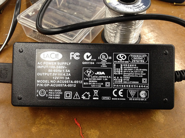
Power
I am using a 12V adapter to supply power to the board.
I managed to get this to work and the system is functional, but I do not have a video up yet. I will, as soon as it is possible, upload a video of the motor responding to the light sensor.
The video below was made during initial testing of the motor.