Image source: MIT Tech
This drawing is incorrect though because it gives the building four legs whereas there should only be three.
One of this weekĺs assignments was to make a 3D-printed material with a design which cannot be made by subtractive methods such as milling. I made a model of the Kresge Auditorium, one of MITĺs popular buildings.
Brief History of Kresge
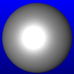
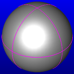
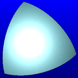
The Kresge structure is composed of a thin concrete shell, one eight of the surface area of a sphere of the same radius, as demonstrated in the image below.
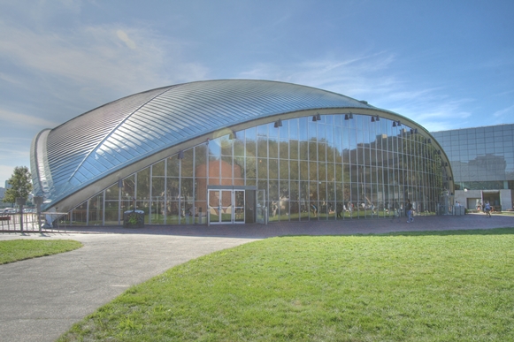
Initially, Kresge was designed to be supported at three points only ľ the three points where the spherical shell meets the ground. But the shell showed significant deflections after the constriction support was removed. So engineers added nine columns for additional exterior support. Because the building is an auditorium, no internal supports were added (so that the stage is visible from all places in the auditorium).
Modeling
The modeling was done in keyCreator in a few simple steps:
I started with a solid sphere of a radius of 21⁄4 inches. I made three orthogonal rings of the same radius around it. I used these rings to slice the sphere, leaving a solid shape one eighth of the volume of the initial sphere.
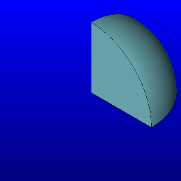
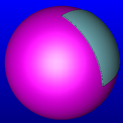
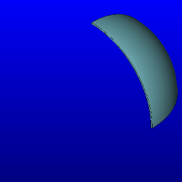
I then created another solid sphere of radius 113⁄64" with a similar center and used a boolean subtract command to subtract the unwanted volume of the first eighth-sphere. This created a thin shell of thickness 3⁄64" or 1.2 mm. I rotated the spherical shell so that it was upright The steps are shown pictorally below.
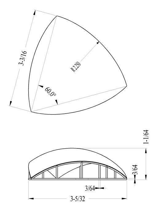
I then modeled the floor slab by projecting the shell onto a horizontal plane and extruding a slab from the projected area. Then, staying true to the original kresge construction process, I added the the support columns last. All pieces of the model including the shell, floor slab and columns were designed with a thickness of 3⁄64". Here are images of the final design, including dimensions. A .stl copy of this may be obtained here.
G-Coding
I exported my little Kresge as an stl file which I then opened in Cura to transform it into a gcode file. Gcode is readable by the 3D printer. It slices the shape into layers and paths which guide the printer as it lays the threads of material. I had to scale my model by a factor of 25.4 because Cura uses a mm scale while I had modeled in inches.
I used the following settings for the printer, defined in Cura:
Layer Height: 0.1 mm
This is the thickness of the discrete layers that the printer lays. This was the default value. It range: 0.06 - 025 mm. Determines the speed and quality of the print
Travel Speed: 150 mm/s
Fill Density: 100%
This was an overkill and probably slowed the printing. Cura says a fill density of 20% is normally sufficient. Fill density determins how strong the structure is.
Cura estimated that my printing job would take 3 hours, 21 minutes.
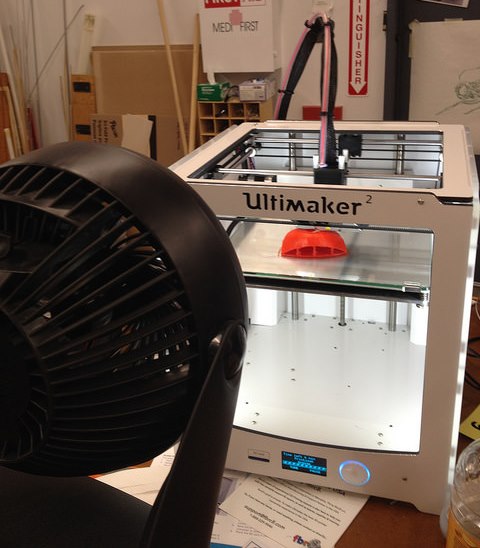
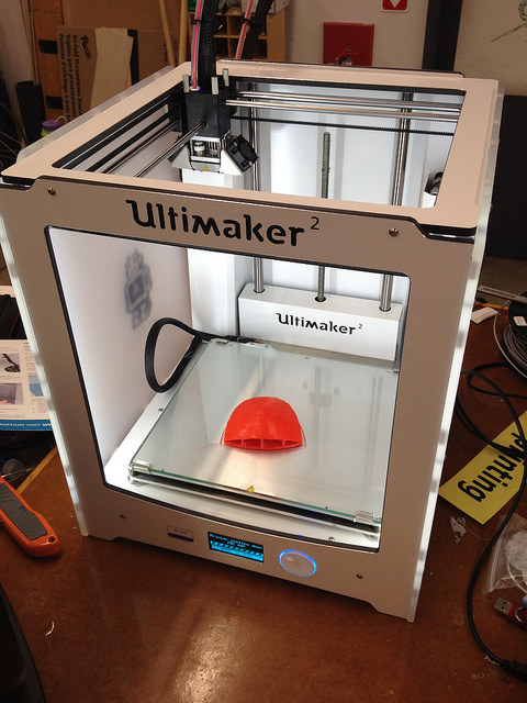
3D Printing
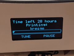
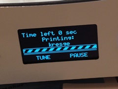
At first, the printer agreed with Cura and estimated that the job would take approximately 3 hours to print. But it grew more uncertain and pessimistic as it worked. The estimated time escalated from 3 hours, to 4, 11, 13, 18, and went up to 32 hours!
I let the printer run for an hour to see if this overestimation was due to a bug. And sure enough, after printing for an hour, the estimaged remaining time began to drop drastically, and stabilized around 2 hours. This was about the time when the printer had finished the floor slab. Had it been scared of the vertical components? Who knows? The job took 4 hours to finish.
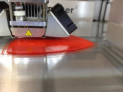
I realized as I printed that I probably should have created a temporaty support structure for the dome (This is the one thing I did differently from the original Kresge engineers who provided structural support as they poured concrete!). The dome wiggled significantly during printing and caused a few inconsistencies in the final product.
Also, the center of the dome tends towards being horizontal and some of the final layers were sagging and/or collapsing entirely as the printer layed them, so I supplemented the printer's cooling fan to quicken solidification. This was a suggestion I saw on several sites. Another solution would be to print the object in a different orientation, such as up-side-down. In this case, however, this wouldn't be a good solution.
The job ended up printing OK, but if you look under the dome, you do see some hanging threads of material at the center.
Finally, I learned not to move or disturb the printer as it works. I was surprised at how easy it was to disturb it (Why did they make it so open?) Vibrations on the table caused slight bumps on the print job. At some point, I touched the printing surface and and displaced it vertically. The path laid poorly and the inconsistency was visible. I also should have cleaned the board before starting the job.The tiny particles on the board prior to printing created small bumps on the base of the print job.
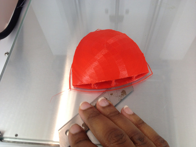
I had to exercise caution as I removed the little Kresge after the printer was finished. The structure was (is) quite thin and delicate and could have failed with the force that it required to yank it off the printer's plate. I slid a steel blade under it to dislodge it.
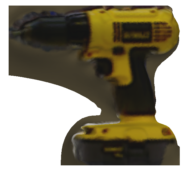
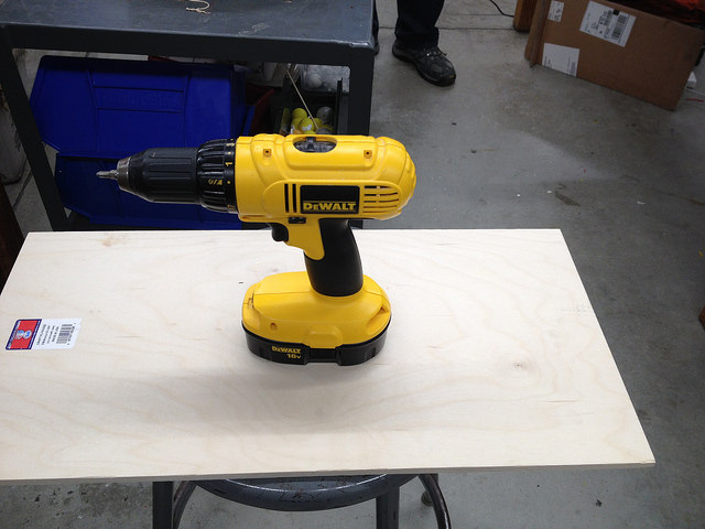
3D scanning was very frustrating. I scanned a drill.
I found several things that the scanner didnĺt like:
1: Moving too fast
2. Non-uniform Lighting
3. Very small objects: The program defines a small object as about the size of a tea kettle. It didn't seem to do well with objects of smaller size.
With any of these problems, the program often interrupted scanning with an error message: "Lost tracking"
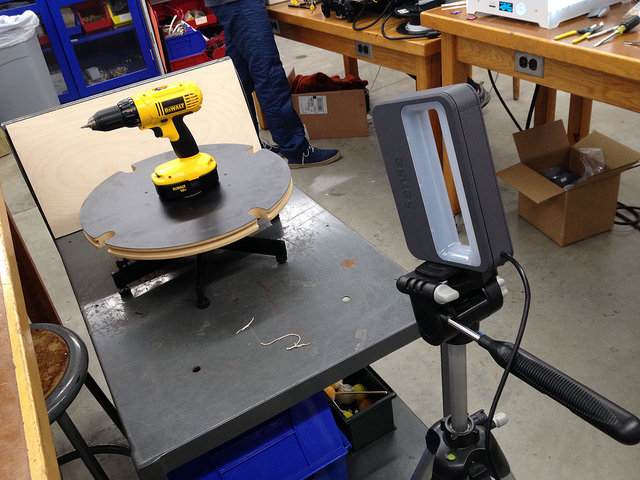
4. Moving objects These confused the scanner. To solve the problem of non-steady motion, Neils helped put together this set up where the scanner is stationary while the object rotates to create a more steady 3D scan.
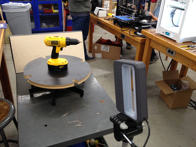
We thought this would solve the problem of an unsteady hand. However, the scanner didnĺt like that the object was moving (it seems that it is designed to be the one to move) and instead tried to merge all views of the object. The result was a Siamese drill!
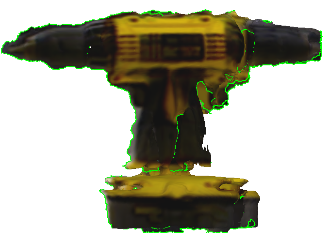
Here is the final product.