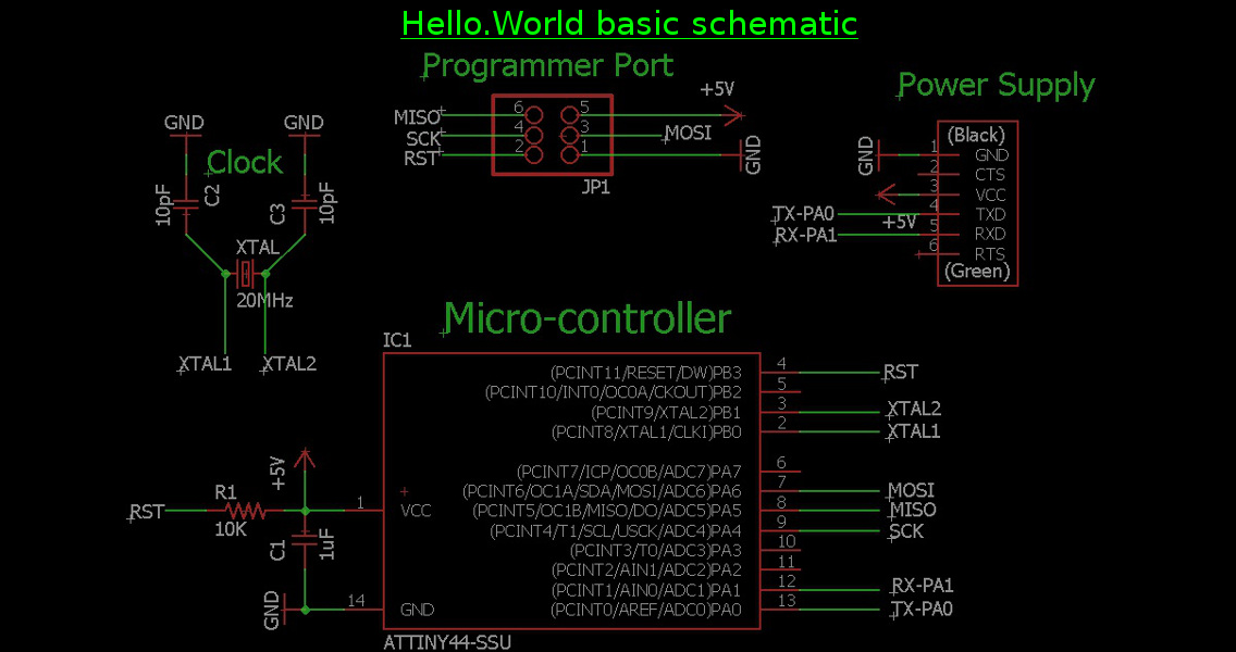
With some experience using EAGLE under my belt, I moved on to the assignment of designing my version of the"hello world echo" board. I started by first working backwards from the traces of the HelloWorld board to create a schematic I could add to.
With that, I started to add my own modifications. After seeing Akash Badshah's design from 2013, I liked the idea of adding solder jumpers which would allow the board to change function after being programmed. Initially, the LEDs would be hard-wired to turn on with the power, but when the chip was programmed these jumpers could be removed to allow for the programmed functions to take over.
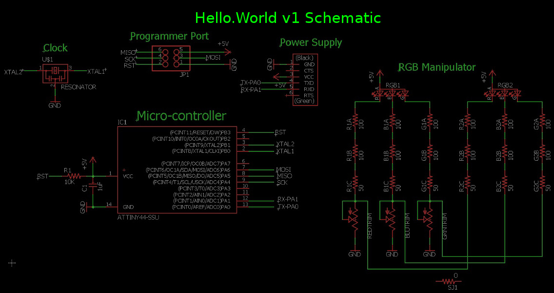
I also liked the idea of playing with the RGB LEDs. These have three separate red, green, and blue LEDs, which had separate cathods and a common anode. I relized this could allow each LED to be manipulated individually, and that with adjustment any color that an LCD monitor could display could also be created here. I thought this could be a useful educational toy showing how LCD screens can display a wide range of colors (though not all colors visible to humans) by using only 3 componant colors of varying brightness.
I checked the RGB LED datasheet to find the maximum current the LED could handle, and determined that a minumum resistance of 250Ω would be necessary. After talking with Rob Hart, our section leader, I found some 1000Ω potentiometers which could be used as variable resistors. This would add extra resistance to the LEDs circuit, effectively dimming the LED it was wired to. I also talked withBen Garber in the Harvard section (who has a good deal of prior electronics experience) for help laying out the board correctly. After this information gathering, I designed a final schematic. Due to time constraints and a shaky understanding of the microprocessor, I ended up dropping the solder jumpers and simply hardwired the LEDs to the power source. I can add these jumpers in a future design, but at this point I wanted to confirm all of my assumptions up to this point were correct.
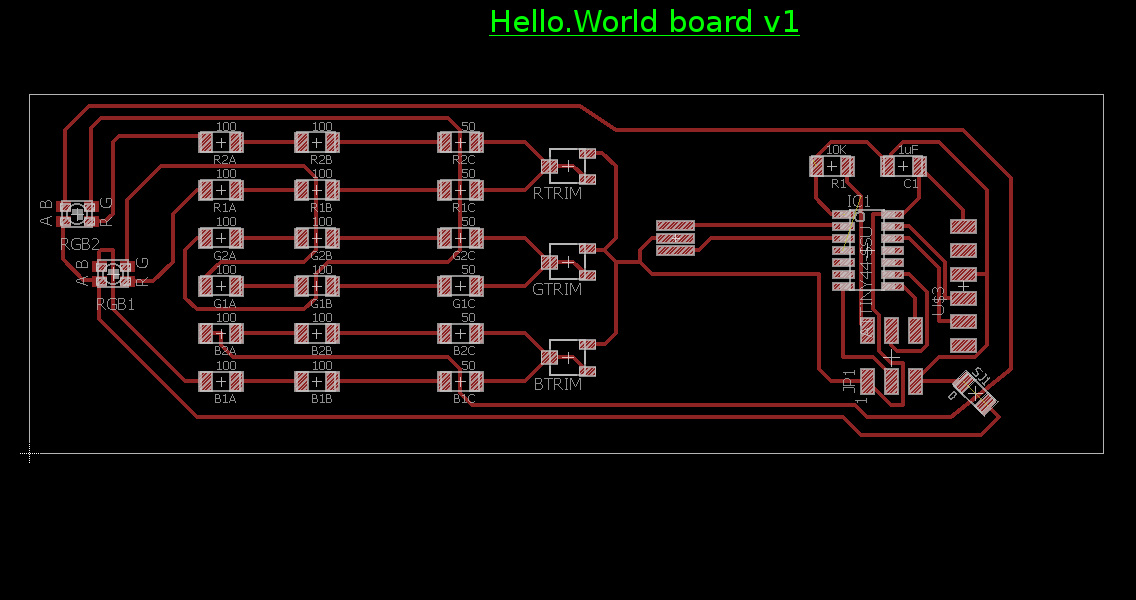
I had difficulties routing the board, and finally decided to add a solder jumper (a 0Ω resistor) to jump over a trace I just couldn't get around. I layed out the board in a 1.5" x 4.5" rectangle, and arrayed the components so they would fit in 3 distinct 1.5" x 1.5" squares, which could be milled and joined at 90 degree angles to make half of the box.
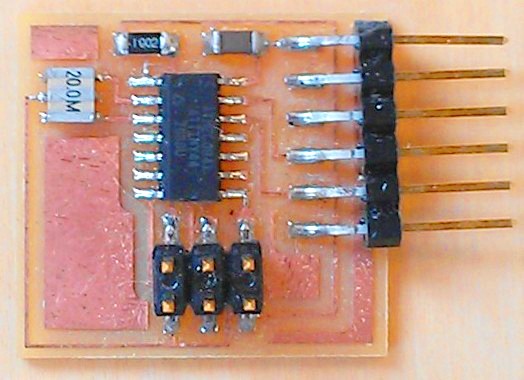
With this, I felt I was ready to begin milling and mounting the board.