Final Project: Wireless microphone
My (redone) final project concept
Originally, I'd thought of making a desktop CNC mill for my final project. Quickly, I realized that this was an idea doomed to fail, as it would take me much more time than I had available. The concept CAD files are still on my website, if anyone wants to see them. I might still make a CNC mill for myself in the future, but if I do I'd probably just make one of the MTM CNC designs (the MTM-LJ or the snap-lock) and mostly focus on doing the electronics myself.
After input devices week, when I first started playing around with the Knowles SPH0645LM4H-BMEMS I2S digital microphone, I realized that a high-resolution (16 bits) microphone like that could be really useful for a lot of things. The sort of wireless microphones that people wire up on actors so that they can be heard need to be high-quality, but mostly have capabilities that can be thrown together from the kinds of things we have lying around: this MEMS mic, the nRF24L01+ 2.4GHz wireless transceiver, and AVR microcontrollers. The technical challenge of learning to use multiple SPI peripherals in tandem would be an enjoyable one, as I'd be pushing the performance of the AVRs and doing something really cool with them.
Another type of product that this suggested to me was a voice recorder, the kind that journalists use to record interviews. Doing some brief research, it became clear that an SD card's SPI interface mode makes it pretty easy to interface it with an AVR. Here's something I read that gave a lot of context for SD card interfacing.I probably won't end up implementing this because of longer-development questions about storage, mostly having to do with file size, given that the size of the file >> size of RAM on the microcontroller. Also, I'd have to learn how FAT works.
The second iteration of this concept was a wireless USB microphone--using LUFA (drivers for built-in USB on some AVRs), I could interface from the microphone chip to wireless and from the wireless to USB. LUFA contains a built-in interface for USB Audio Class 1.0, which allows use of the built-in drivers for microphones on most computers.
It's pretty clear to me that the best route for getting started is to begin with the USB mic idea (much easier to debug, as it won't have a wireless chip as a (slow-to-develop) middleman.
The microphone project: My idea was to create a wireless microphone, potentially the kind that can clip onto your shirt.
Learning LUFA
LUFA: The Lightweight USB Framework for AVRs
LUFA, I'm told, is the most powerful and usable tool for adding (Full-Speed) USB (up to 12 Mbit/s) to an AVR project, and especially if you want it to use one of the built-in USB classes (HID--Human Interface Devices, which have standardized drivers and therefore don't require the user to write a driver). As I'm hoping to have a USB microphone mode, I'd need this capability just to be able to avoid writing drivers. Furthermore, the hardware USB is necessary for high-speed data transfer--at the data rates I'm using (upwards of 1Mbit/s), software serial would use up all the processor time, and it's much too fast for UART. That's because Shannon tells us that to effectively sample a 20-20kHz signal, we need to sample at at least 40kHz (usually one samples at 48kHz for 20% oversampling, which improves the signal). At the absolute minimum sampling rate for high-quality audio, that gives a data rate of 40kHz x 16 bits = 640 kbps, which is much too high for the 115-ish kbps of high-speed UART.
Anyway, the build system for LUFA is pretty complicated and mostly involves using a serious stack of Makefiles to choose source code. Luckily, its developer, Dean Camera, ported it to Atmel Studio, which should make it moderately usable for my purposes. Although Atmel's ASF has pretty poor AVR8 support, LUFA has a lot of custom small drivers which make it easier (i.e. for peripherals). It looks like it's going to be pretty difficult to work out the layers in between the main program and the drivers--it seems like there are a lot of things that need to be developed separately (especially because Dean Camera's code involves the design paradigm of really tall heirarchies of libraries).
The ATmega16U2
I'm trying to learn to use the ATmega16U2 microcontroller beginning with the basics of reading the datasheet. A couple things popped out at me immediately: first, the fact that there's bootloader support, and second, that there's an onboard 3.3V regulator for powering the USB part. For the onboard regulator, I wonder whether it can source the current I need for the RF chip (some 11-13mA) and whatever other things I'd want to have onboard (say, LEDs). For the bootloader, I want to know whether they were nice enough to preload it with one, or whether I need to figure out a way to program the board (frankly, I really don't want to have to fit an ISP header onto this board, especially considering that I'll want to use the same pins for the RF chip).
Update! Prof. Gershenfeld sent me over to Andrew Mao's work on this from last year, which tells me that the mega16U2 chips do, in fact, come preloaded with Atmel's DFU bootloader. Also a couple important notes I got from there: The USB data pins need impedance-matching resistors at a value of 22 ohms (which we don't have, so I'm approximating with 20 ohms), and the dfu-programmer module only allows wiping the entire memory and rewriting it, so I'll have to work with that as best I can.
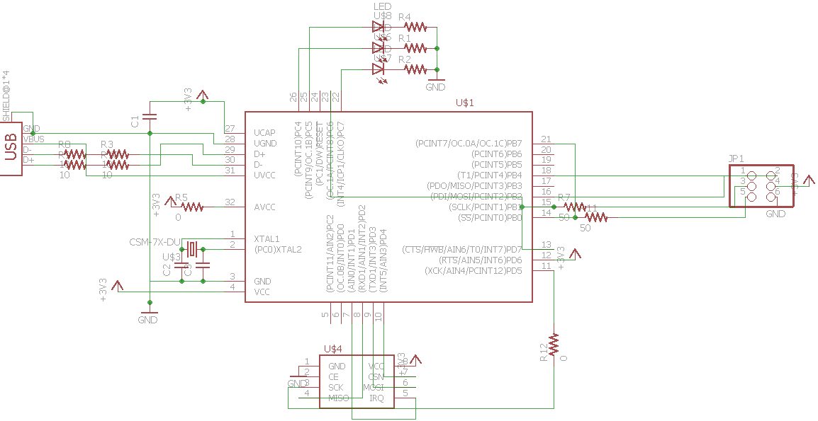
Final board schematic: The design of the final board was tough because of the uncertainty about crystals--more on that later.
First boards: Challenges
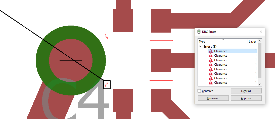
DRC failure: Aah! Apparently I still failed to fix the MEMS microphone pads after I decreased their size. Here they are setting off DRC errors.
Manual PNG editing: I had to manually edit the PNGs for the traces because they were too close to machine with the 1/64" end mill for both the RF module and the MEMS microphone.
I started out trying to make a Fabduino optimized for breaking out SPI headers, then realized that this idea was pretty pointless as I need to have the specific pinout for the wireless module in order for that to work. Then, I moved on to making a first USB board, focusing on fitting on the microphone and wireless module. That was much more successful, except for my repeated failure to put in necessary parts: I forgot about the series resistors for the USB.
Then, I began to read through the datasheet. Unfortunately, it became clear that my plan for interfacing with the finnicky I2S audio interface was bound to fail. Unlike the USI interface on the ATtiny line, the built-in SPI and USART (either SPI mode or synchronous mode) are both made to send bytes as packets, not as continuous streams. The microphone (as I discuss in my input devices post), is very finnicky and wants to have a continuous 2-4 MHz bit clock and carefully synchronized word select strobe. This suggests that the best way to take in the data without bit-banging is to use the SPI module in slave mode, using the timer/counters to run the clocks and have the WS (I2S word select) and SS (SPI Slave Select) pins connected, so that the microcontroller's blind-master Timer/Counter pins control both the microcontroller's SPI module and the microphone as I2S slave devices. I think I need mode 1 on the SPI slave to correctly synchronize bytes, as it shows the rising edge as the first edge with SS low, and also has the falling edge of SCK as the sampling edge, which is what the I2S bus requires.
At first, I was worried about two possibilities: first, that the microcontroller would lose the last byte of the audio data (as its eighth falling edge is the one on which SS toggles), and second, that the frequency would be too high for the SPI module. Turns out, the SPI module does lose the last byte of the 32 bits while SS is low, but that byte is junk because there are only 18 bits of data anyway. Furthermore, it's not too fast for the SPI module because that can capture at up to 1/4 system clock speed, and I was hoping to use a 16 or 20MHz system clock anyway.
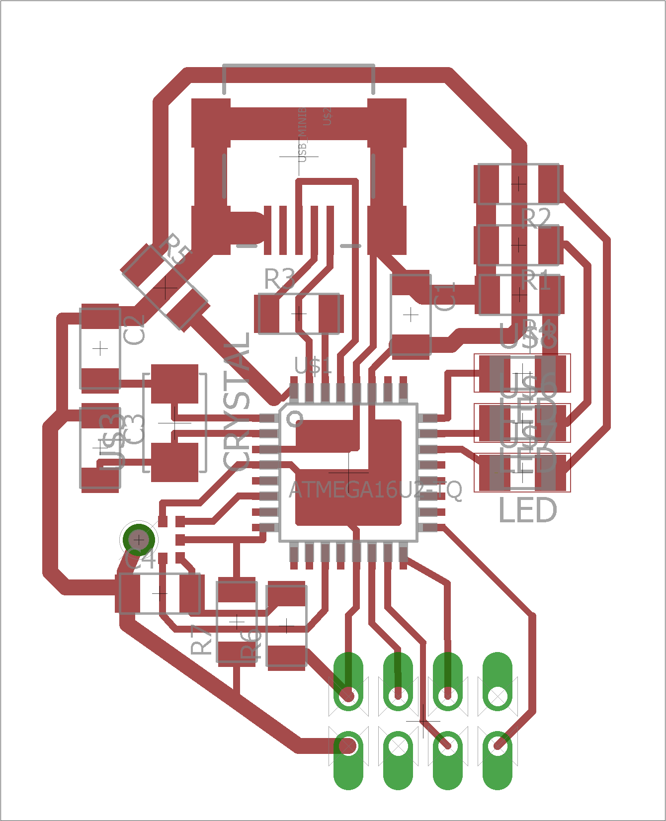
First USB attempt: In the first attempt, I managed to fit everything in a really small area (I think around 1.5x1.5 in), but put the microphone on the USART port and the RF module in almost the worst possible position: on top of the board and covering up the LEDs. Most importantly, and what I noticed first, I forgot the series resistors for the USB port.
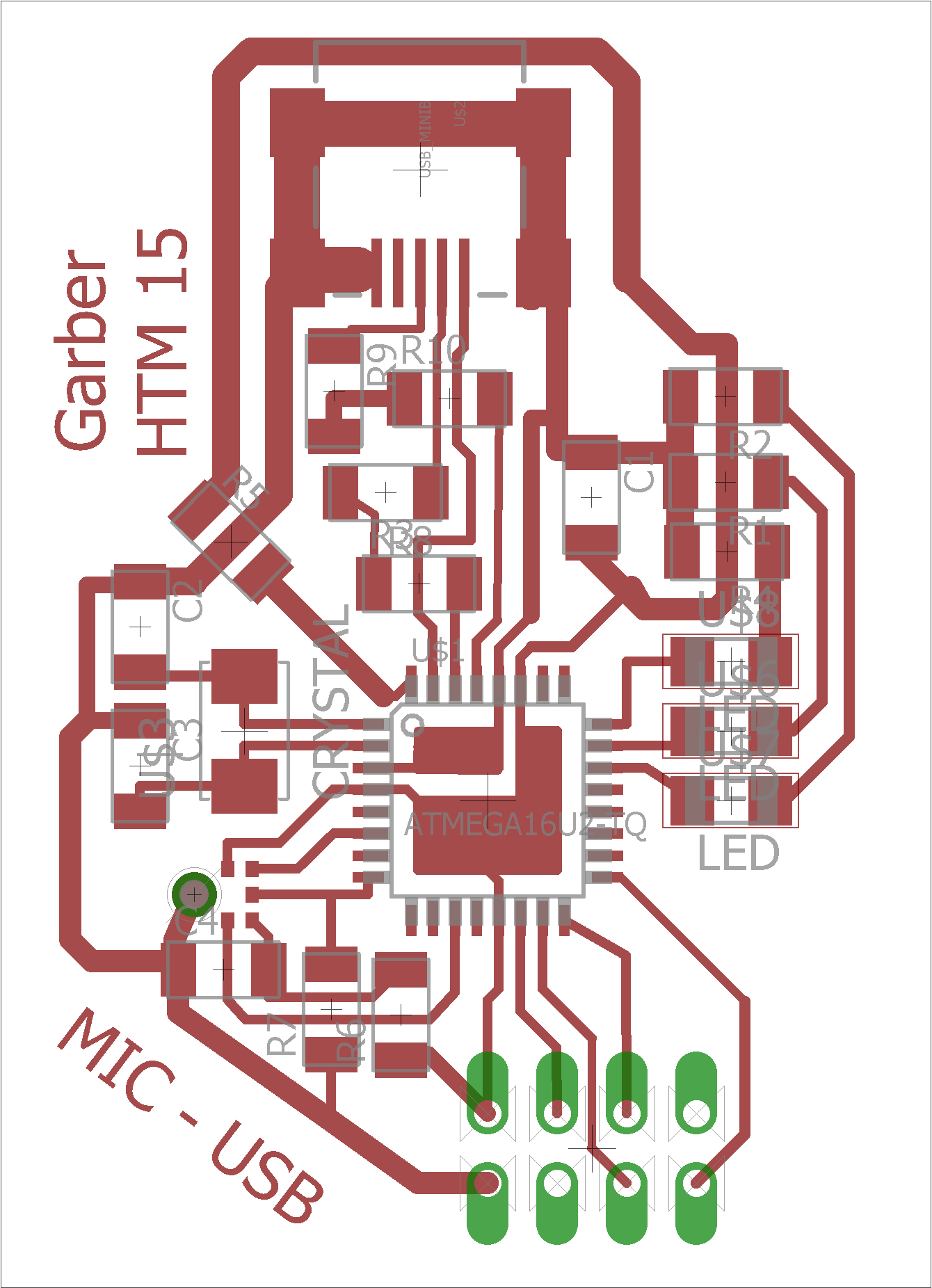
Another try: This time, I successfully added the series resistors, unfortunately lengthening the board a bit. Luckily, I didn't have to do a complete redesign--slight redesigns are mcuh faster.
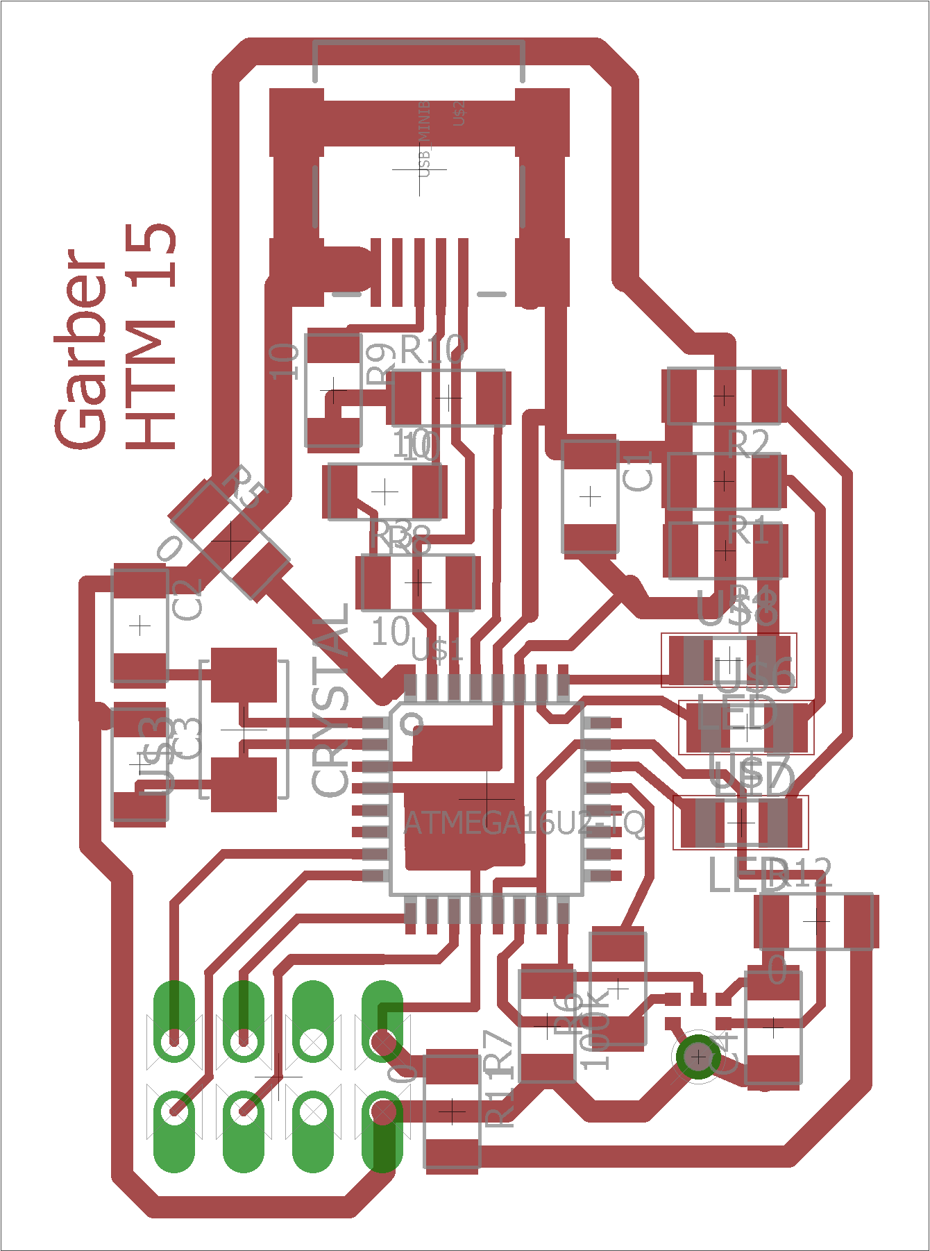
Third try: In the third attempt, I switched to the approach described above, where both the SPI and microphone are treated as slave devices by the dumb clocks. Also, I switched the RF module to be behind the board.
The final (I hope) redesign is at least as dense as before, but is changed to do clocking right.
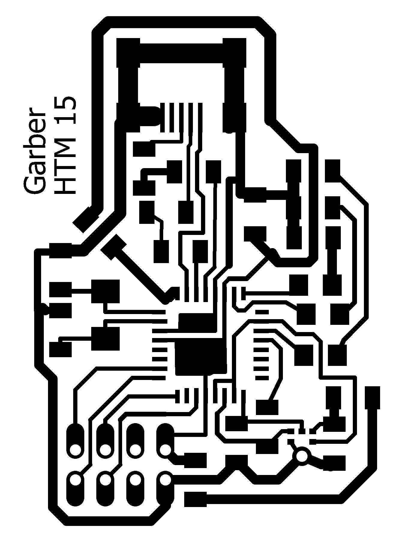
Traces: Pretty clean, lightly cleaned up as above.
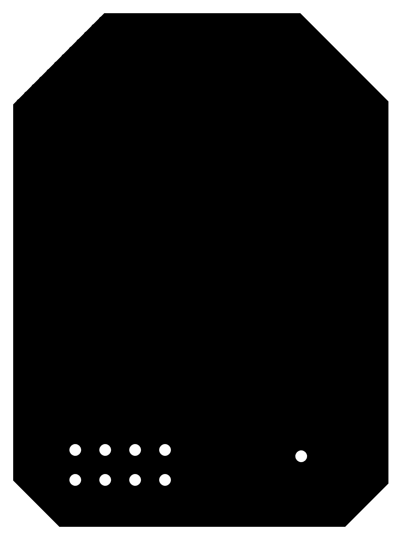
Outline, holes: This requires very little editing, just a couple of paint buckets in MS Paint to make it a solid shape except for intentional holes.
As promised, you can also download the Eagle files.
Some scares
I freaked out a bit Sunday night when I realized that, to use Full-Speed USB (which is necessary for the USB audio to work at the audio quality I want), I need a 16MHz crystal: the ATmega16U2 strictly requires either a 8MHz or a 16MHz crystal, and the maximum data rate for the SPI module is 1/4 system clock, which prevents me from using an 8MHz crystal with 4MHZ bit clock. Also, I won't be able to use the 20MHz crystal as a clock source on the wireless board either, as the Timer/Counters can only generate frequencies that divide sysclk/2. I could do 10MHz/3 for a 52.083 kHz bit rate, but that's an ugly number so I'd rather not use it.
This wouldn't be a problem, except that the Harvard shop only has 8MHz and 20MHz crystals. Luckily, Dan is saving me by bringing a 16MHz crystal from the CBA shop for me.
Unfortunately, I'm still in trouble for the wireless board, which also can't produce the right clock signal for the microphone with its 20MHz crystal. One possibility I've thought of is to use an ATtiny45 as an I2S clock source, using an 8MHz crystal as the tiny45's clock source and then using the same Timer/Counter setup to generate the required output clock frequencies. Either the entire mic+clock source setup could be powered from a single pin of the main microcontroller, or INT0 could be used as a waking pin (I'd want to idle the processor almost always, to save power on the battery-powered part). The main microcontroller will still be able to listen on its SPI port, because it'll be running at 20MHz.
Update! I've been saved again: They sent both a 16MHz crystal and a 16MHz resonator--I can use the latter for wireless if I get there.
LUFA struggles
LUFA is hard to learn. Not only are there hundreds of files and thousands (or maybe tens of thousands) of lines of code, but also the documentation is a spec, without any real guide or datasheet that could be used to help develop a project. The example projects exist, but they don't seem remotely adequate for the type of development I was doing. After trying and failing to open an example project in the ASF in Atmel Studio (which would, ideally, be the best setup for me to use LUFA), I ended up downloading and reading the source files for the Audio Input Device example.
In writing my program, I had a lot of trouble getting things to compile. Although basic programs tended to work, ASF and LUFA are barely compatible, and both try to force you to write board files in their own directories. Ultimately, as I'm not making extensible boards, I chose to have all of the definitions in the local directory (for my final code, the one that compiled.)
Test program: Here's a video of the test program I loaded to test out Atmel FLIP, which uses the bootloader to upload new code over USB.
Finally making the boards
After finally giving up on my fear of breaking my one 16MHz crystal, I ended up redesigning my board to put the microphone on a different, little board that could be more easily embedded in a microphone stick or shirt clip. Unfortunately, I forgot that the ISP header takes up a lot of vertical space, so to make up for that I glued that into the top of a piece of PVC pipe, which I was planning to turn into the handle of a colorful semi-3D-printed show-style microphone.
The first iteration of the board didn't work--I think that my difficulty soldering the microcontroller led me to heatgun it to death, so I had to make another board. This one worked better, except that twice I forgot to solder necessary parts, including a jumper on the ground line that disconnected the microcontroller. This one was successfully recognized by my computer, so I opened up the device programming part of Atmel Studio to try to load a blink program over the bootloader, and it... fizzled. I didn't have time to debug Atmel's DFU programmer, so I downloaded their basic GUI DFU programmer, Atmel FLIP. This was very convenient to use, and I successfully loaded the blink program. However, with a program running it can't recognize the bootloader! In the end, I realized that the only way to reprogram was to manually short the RESET pin to ground.
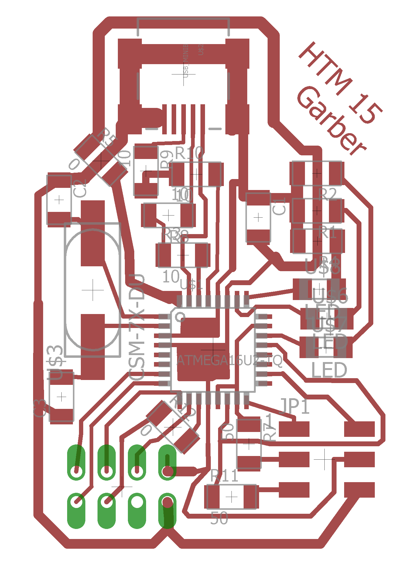
Final board design: Now with separate board for the microphone, notice the resistors for impedance matching on the line to the mic.
Or go to the files directory.
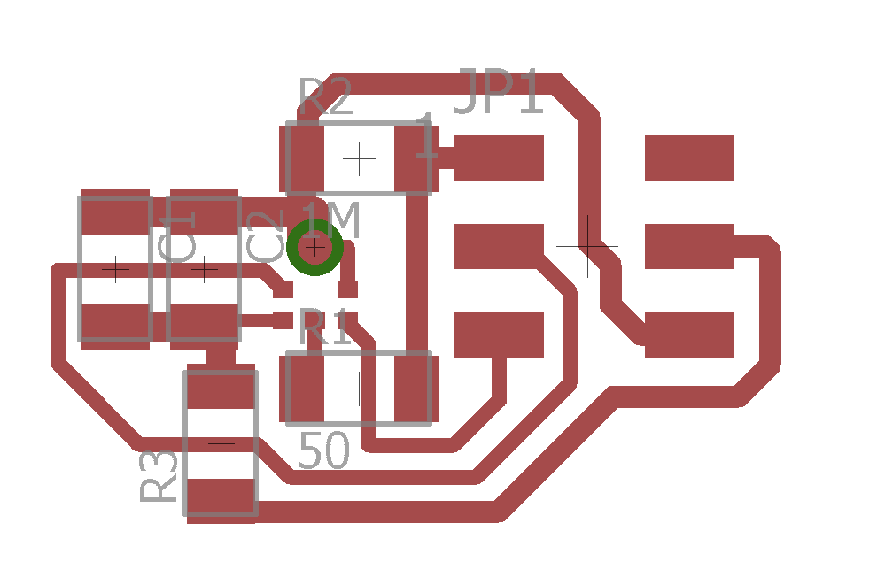
Microphone board: Now with extra capacitors and an impedance-matching resistor for the data line.
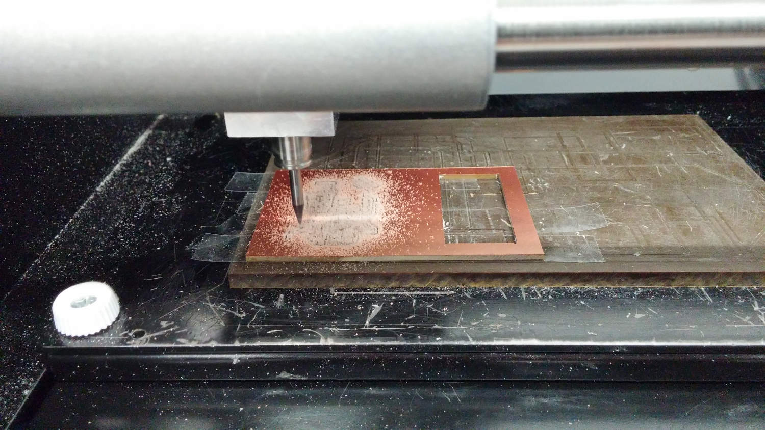
PCB milling: No surprises in the PCB milling process--although the board took some 22 minutes to mill, setup and cutting went really nicely.
Final board programming
More on the code development: I ended up working a lot just trying to figure out how to get the program to build with LUFA. My first attempt, I tried to take the files from the audio input LUFA demo file and meld it with custom ASF-style board definition and initiation files, adding in the LUFA files as needed to add USB functionality into the microphone code. Unfortunately, this didn't work as hoped--no matter how much I fiddled with the code, I couldn't prevent a bunch of errors.
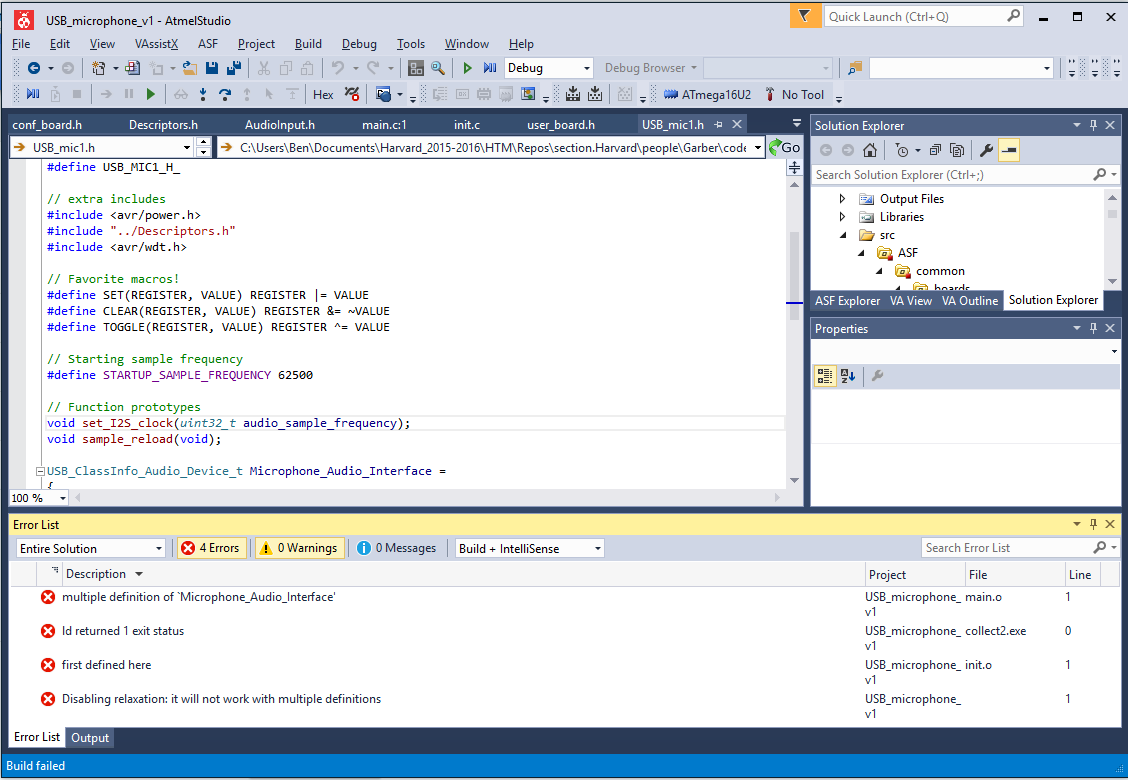
Compiler errors: This was the best I could do after a few hours of fiddling.
I ended up needing to start again from scratch, importing only the LUFA modules used by the demo program and reducing my files to 5: a main program file, two headers, and two included .c files. It took a lot of cleaning to get all of the functions set up in the right header files, but in the end it compiles nicely. You can find the code here or download the entire Atmel Studio solution file here.
Starting up the bootloader: I needed to manually ground the RESET pin to get the bootloader to launch instead of the user program. The FLIP program is basic, but very easy to use.
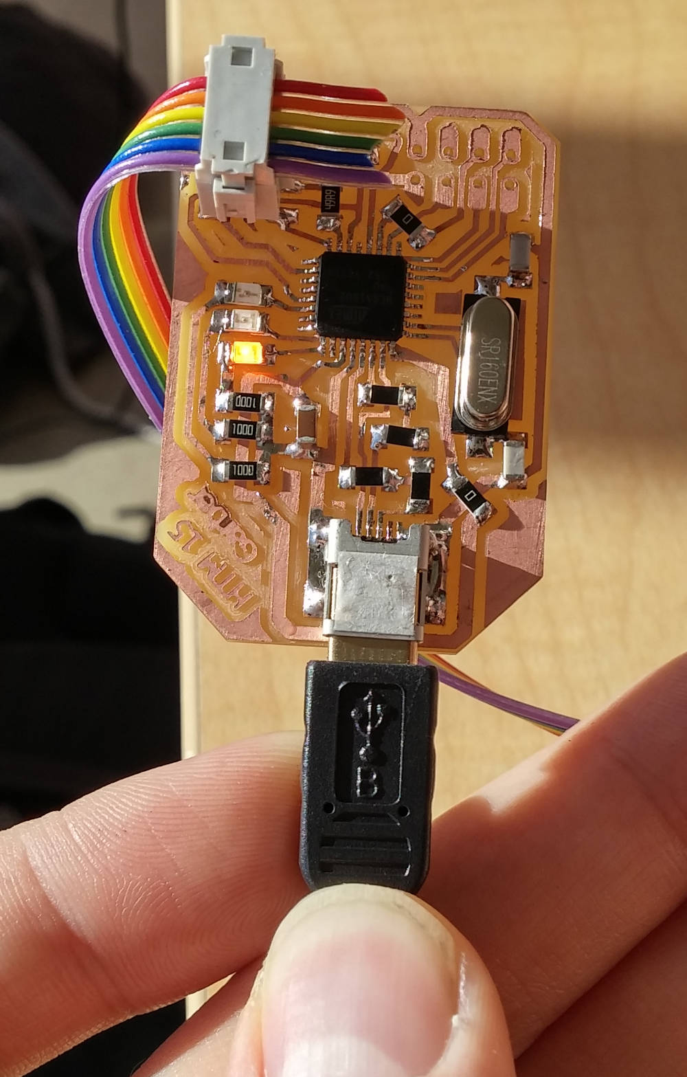
Running USB: The LEDs change patterns depending on what the USB is doing--this pattern is LED Working.
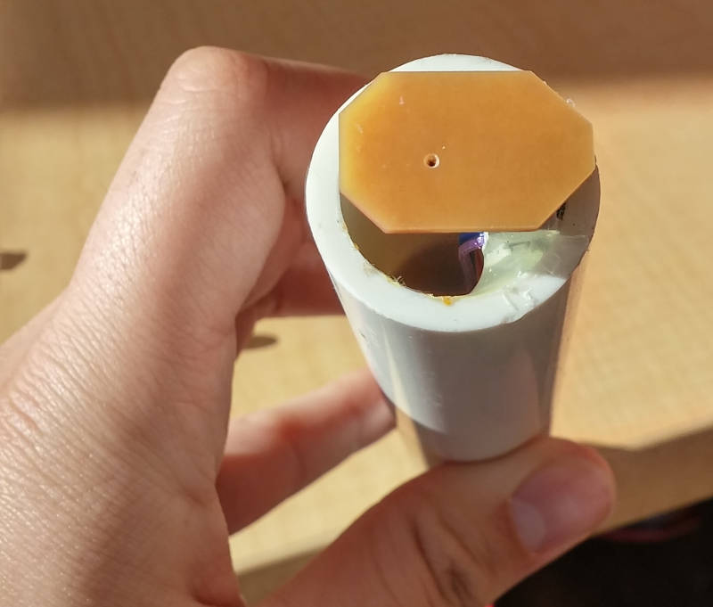
Microphone in a pipe: I had intended to 3D print a cool cage for the top of the microphone, as well as casting another microphone board into a clip. However, Solidworks stopped working on my computer and I wasn't able to design it before the deadline.