How to Make (almost) Anything
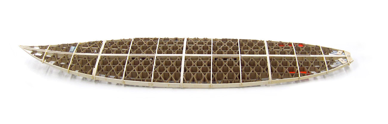
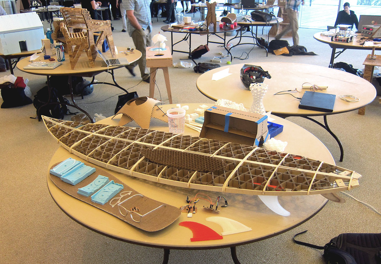
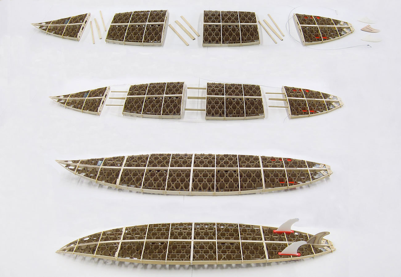
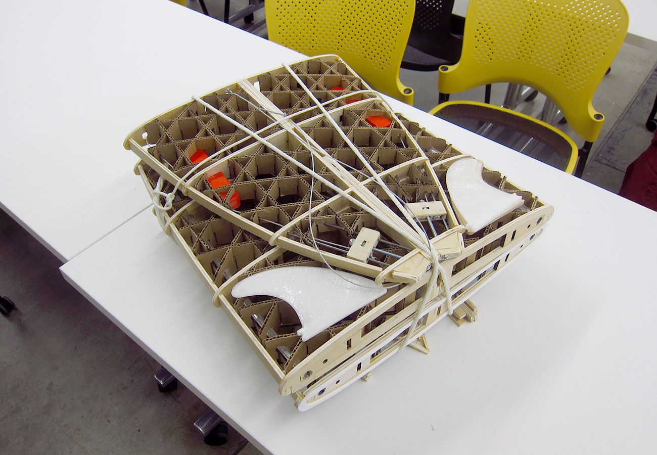
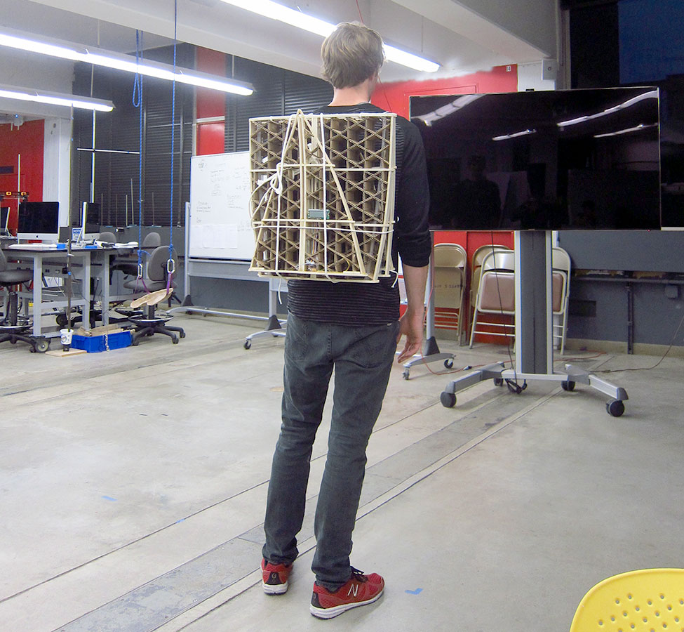
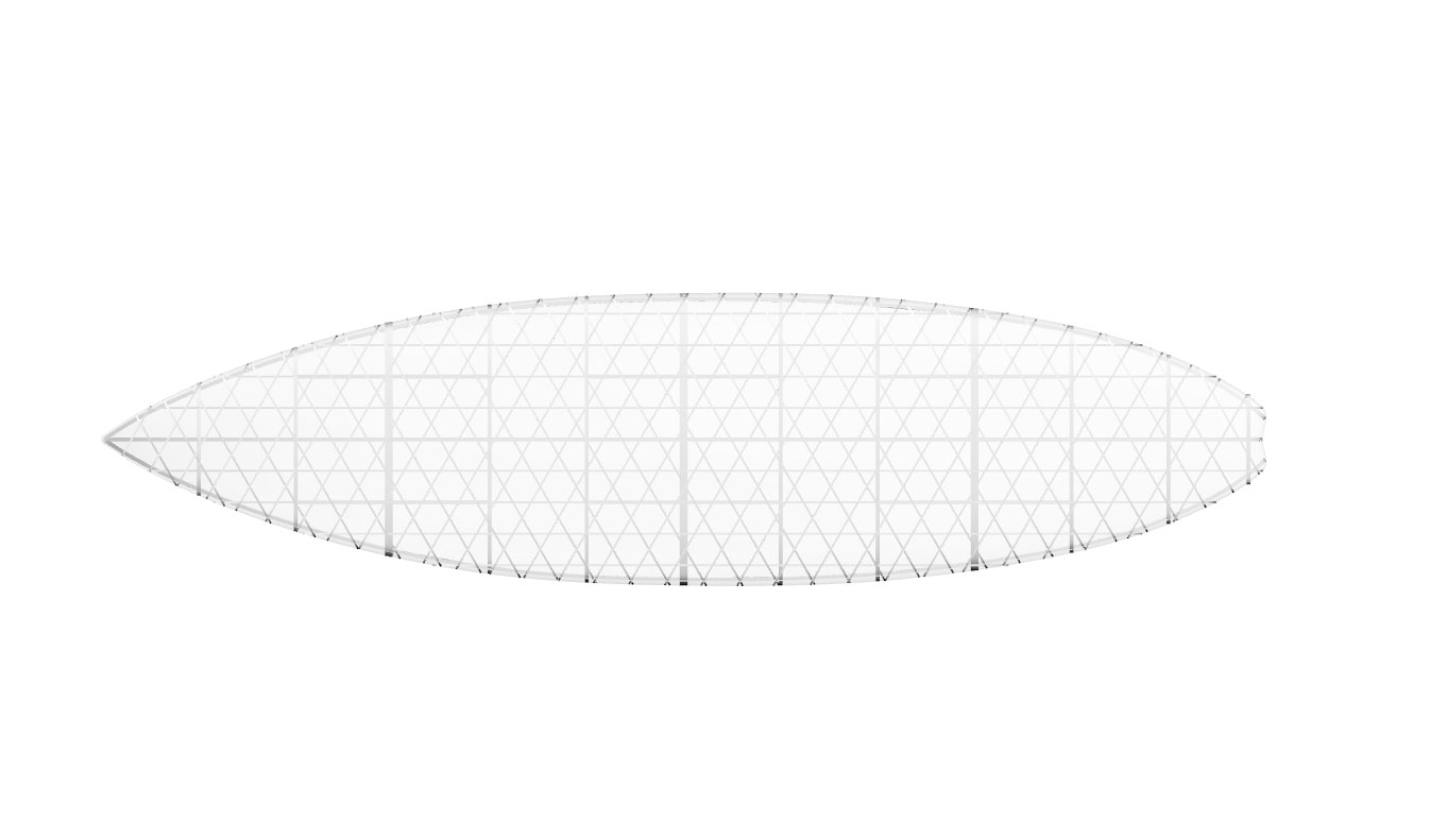
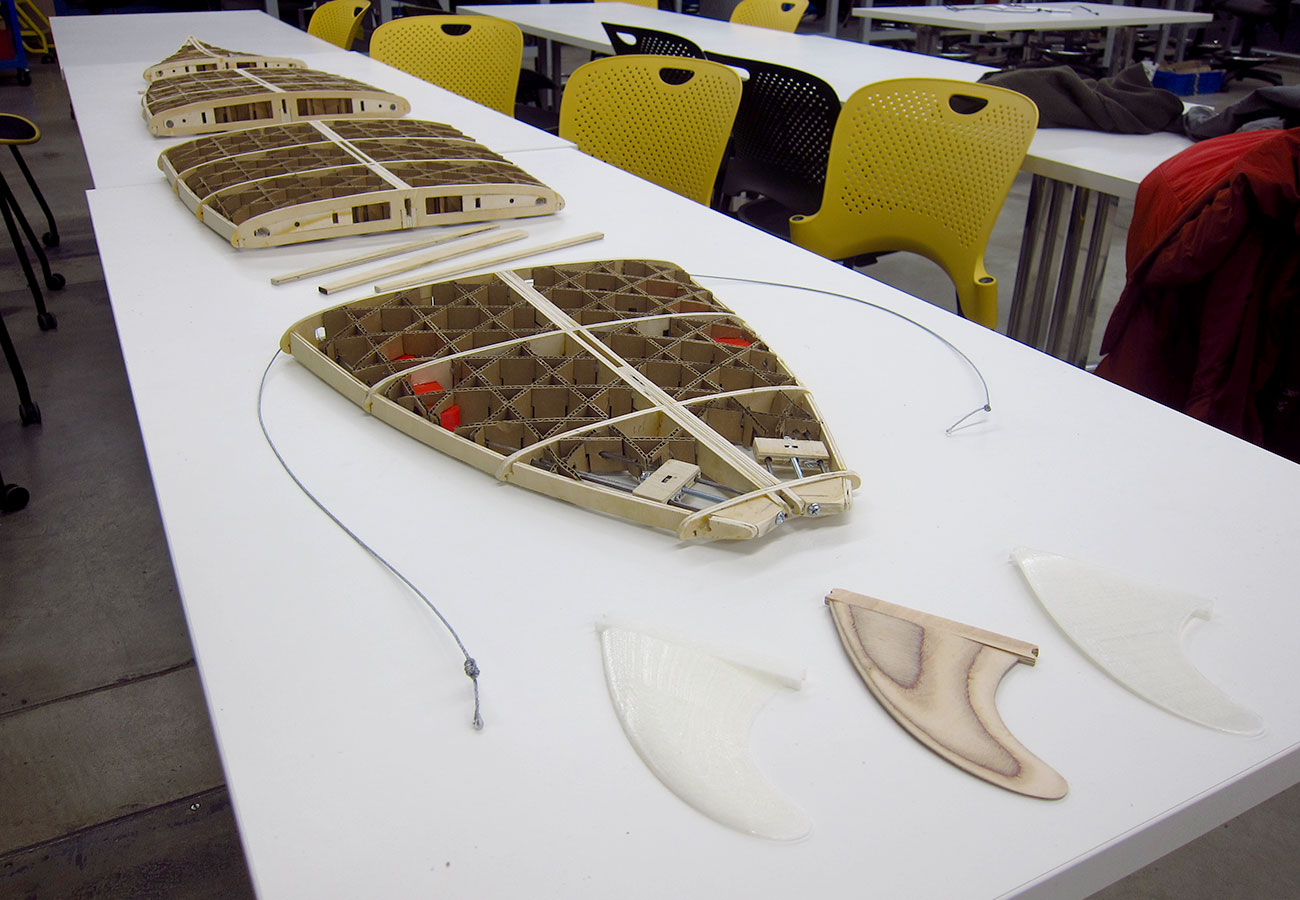
For my final project I was able to build upon some of the work completed earlier in the semester to create a modular surfboard. The design goals for this surfboard are portability, interchangeability, and aesthetic quality. In its fully assembled state the board is 74" long, 18.5" wide, and 2.25" thick, and when broken down into four segments and stacked the overall dimensions are 18.5" x 18.5" x 8.5". This is about 3" too wide to be taken onto a plane as a carry-on item, but easily fits into a checked bag and can be worn as a backpack. Air travel with a surfboard is a common pain point in the surfing community due to potential for damage and airline board bag fees. Domestic airlines such as United and Delta charge $150 each way to transport a roughly 10 pound object which nearly amounts to the cost of a new board for a round trip. My modular board design circumvents this issue for air travel and enables the possibility of carrying your board on your back while riding a road bike or motorcycle and generally transporting in tight spaces such as an ultra compact car.
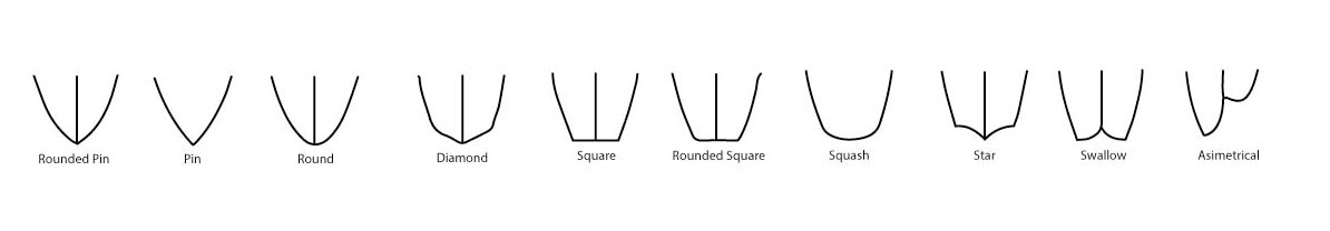
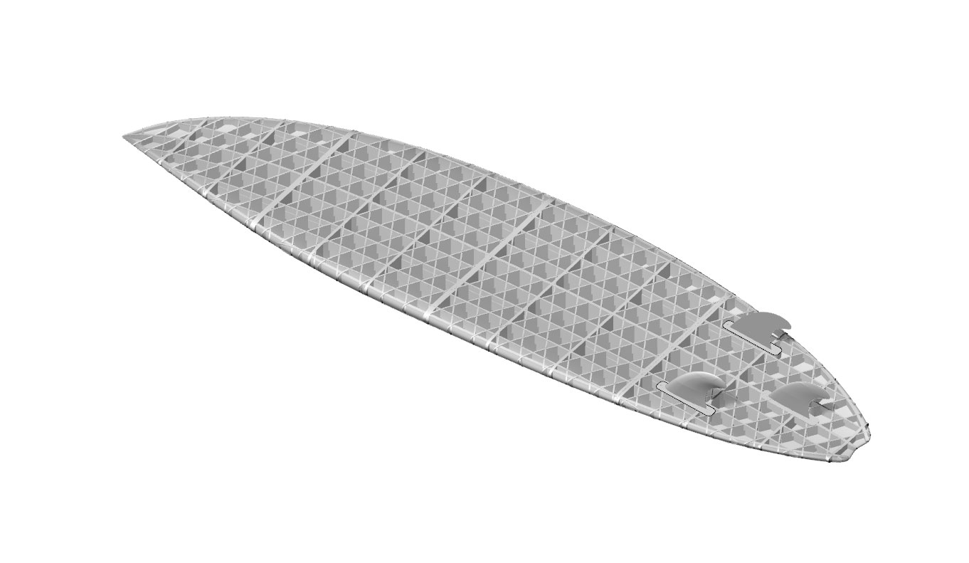
The modular nature of the design also enables swapping pieces out for different shapes and profiles. The tail section is a good example for why this may be useful. There are many different tail shapes that are created for specific types of waves and hydrodynamic performance characteristics. As a surfer's skill level progresses or when location or conditions change, a different tail shape may be optimal and the modular board can easily interchange with another piece. There is also the possibility of replacing the front half of the board with 3 pieces instead of 2 if the waves are smaller and more bouyancy and paddle speed is desired. Board modules can also be replaced individually if they get damaged and there are also opportunities to have dedicated embedded circuits for different purposes. An example is if a surfer wants to use a board mounted GoPro video camera they might choose the module that has embedded flexible solar panels on the deck of the board which charges a li-po battery to power the GoPro.
The design for this board is based on several references and sources of inspiration. Mike Sheldrake is a surfer in Southern California who has developed a carboard surfboard production system. He provides an excellent build guide for cutting and assembling a cardboard surfboard on his website here. His board design is focused around the quarter isogrid pattern, which one can find more info here. I also drew inspiration from a board design by Kevin Cunningham of Spirare Surboards which implements a thin wood honeycomb structure enclosed with solid wood rails.
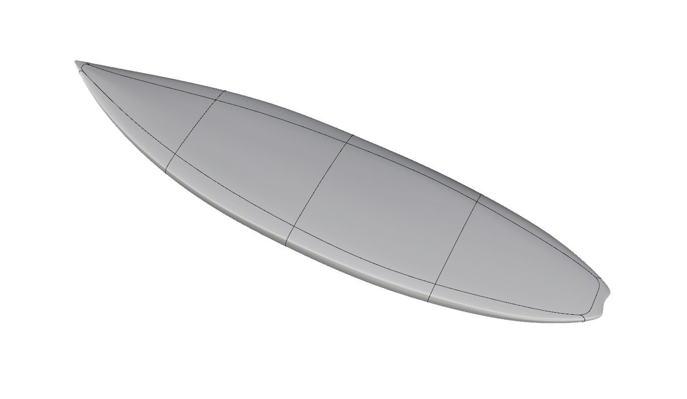
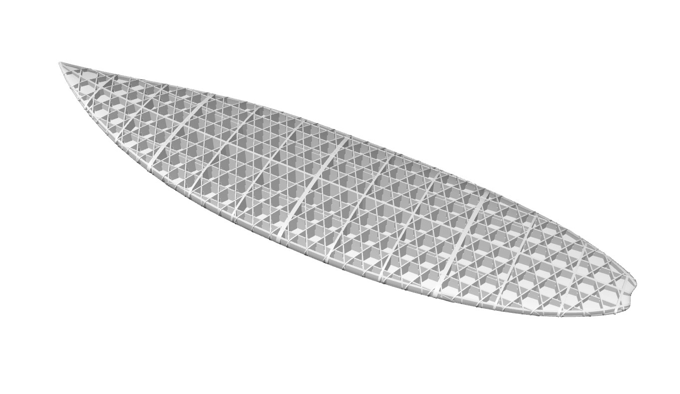
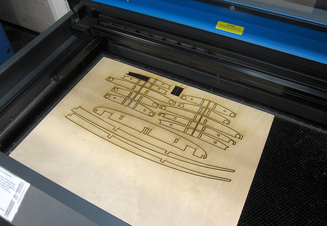
The design for the shape of the board and primary plywood structure is documented on my Week 5 page. I then generated the secondary infill structure which is the quarter isogrid cardboard. For this I worked with Rhino and Grasshopper to create a script which will generate the correct pattern positioning and the correct notch sizes based upon a given material thickness, which in this case is 1/8th inch cardboard. I then edited the two independent structual systems so that they would fit together and allow for pass-through holes for the stringer struts and tension wire tubes.
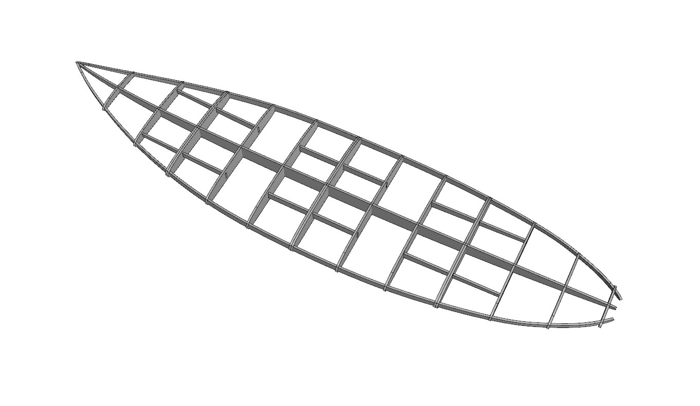
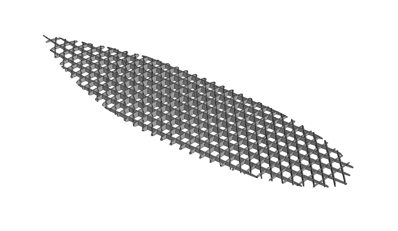
After lasercutting the cardboard and a handful of plywood insert pieces, I wood glued each segment together while clamping each peice to ensure orthoganal orientation. The plywood that I am using is low/medium grade and some pieces were significantly warped which added to the necessity for careful positioning while gluing. I was then able to assemble the cardboard puzzle pieces and infill the plywood frame.
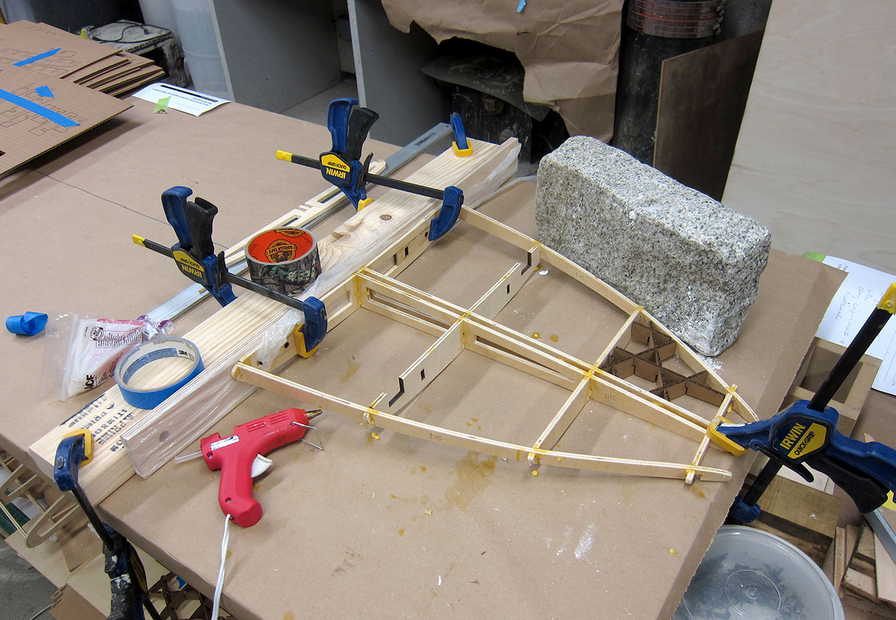
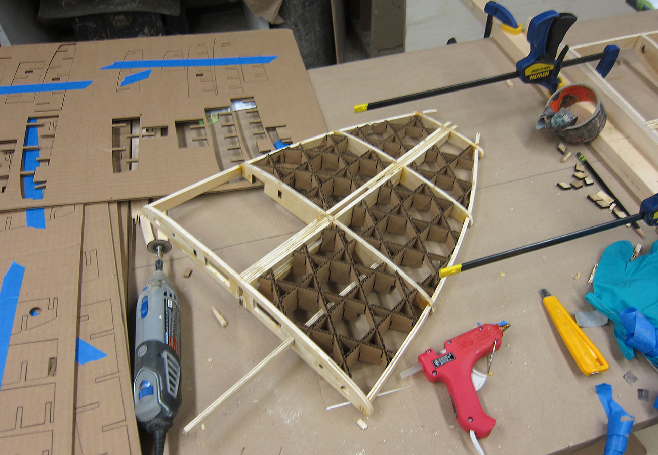
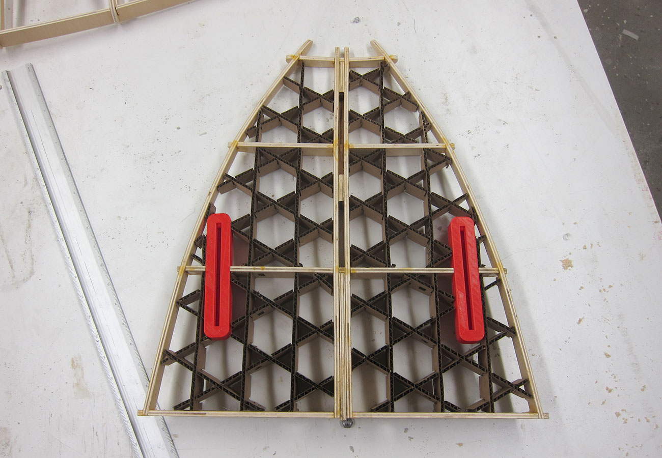
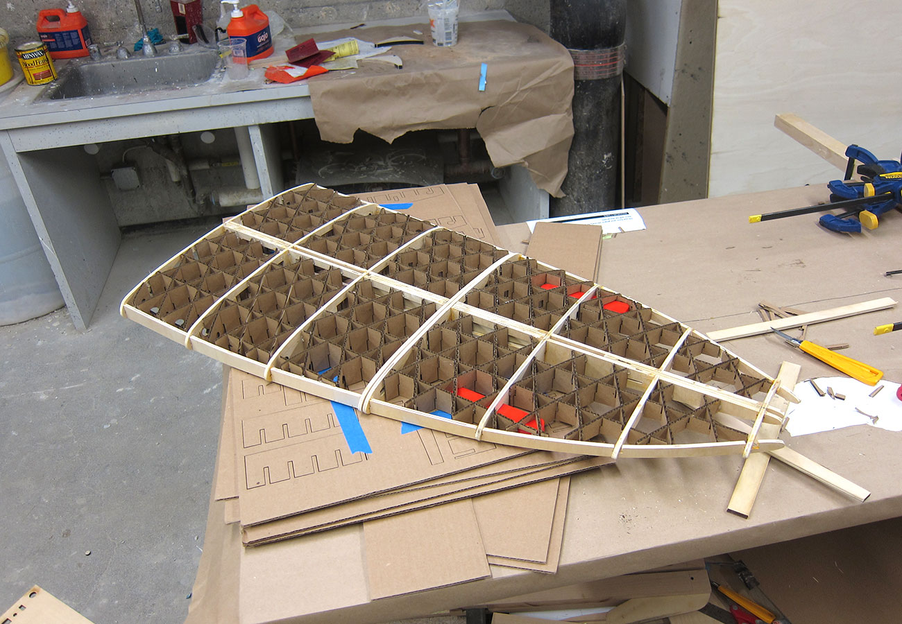
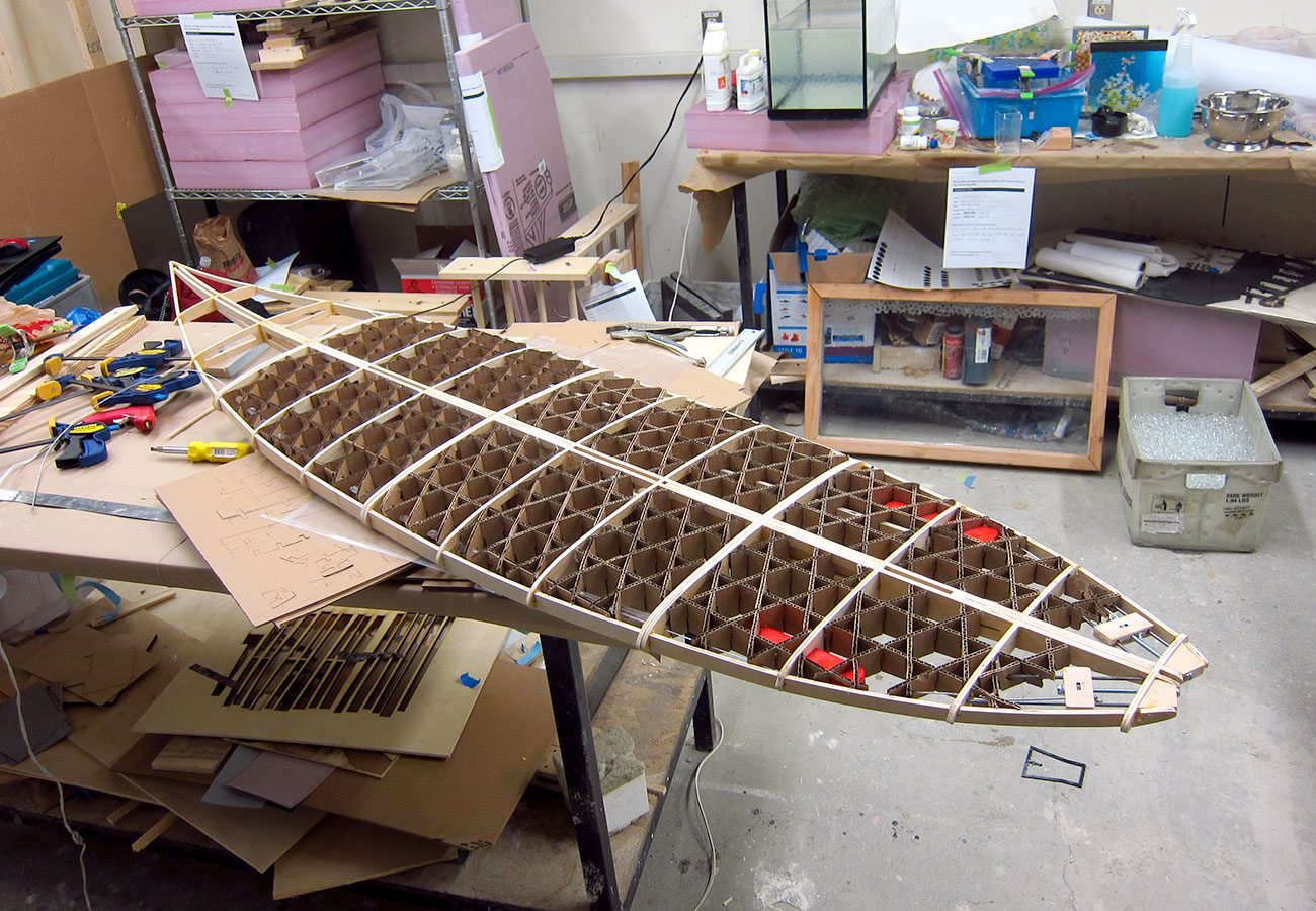
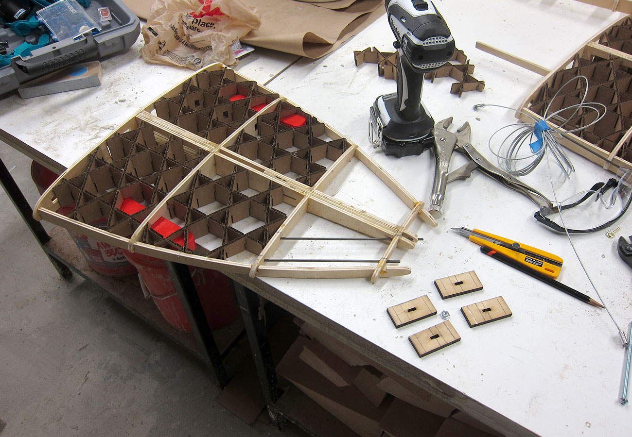
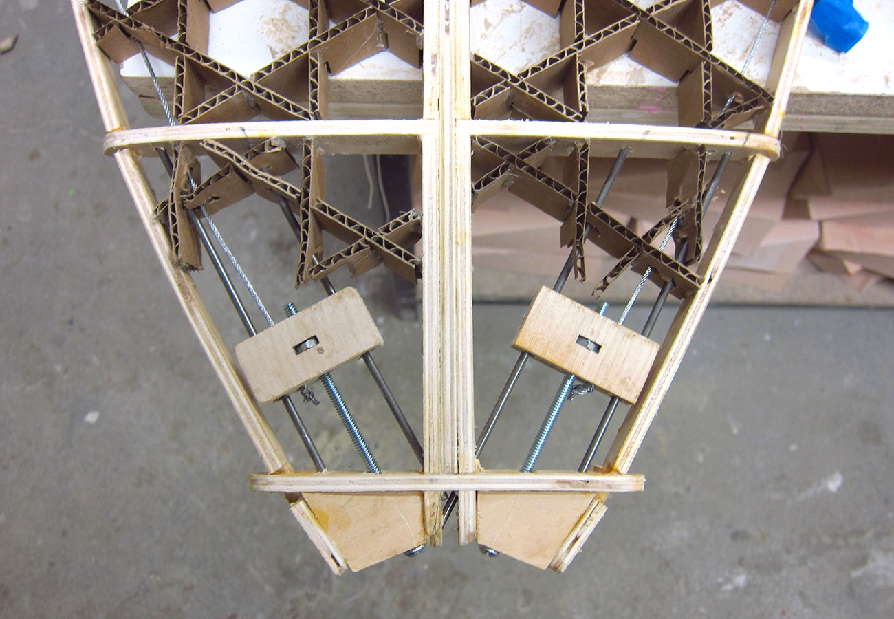
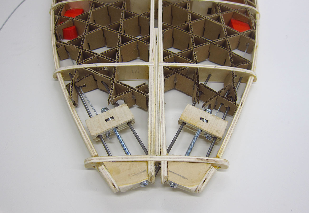
The assembly design uses plywood stringer struts which span across the connection joint of two adjacent pieces. These are necessary to align each piece with its neighbor during the assembly, but also work to resist the bending that occurs where two pieces meet. The four elements now have to be held securely against one another to prevent a break in the seam which would allow water to get inside. This is accomplished by cables which run along the edges and are held in tension by a carriage on a track that pulls as a bolt is turned.
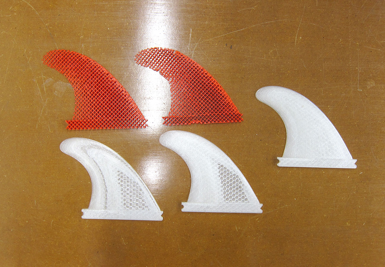
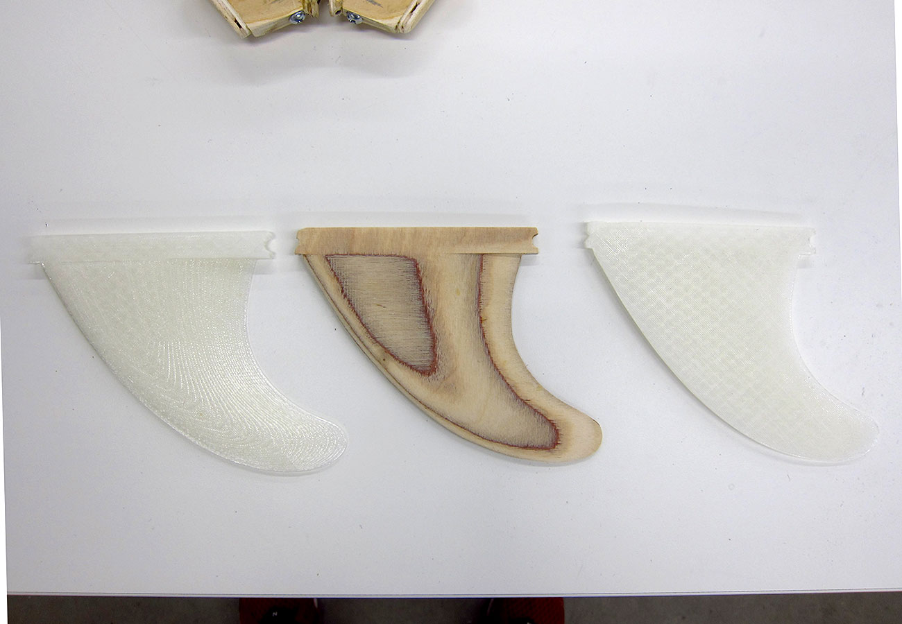
I found a surfboard fin set 3D model online which I used as a reference to create 3D print and cnc mill files for my fins. The center fin was milled out of plywood as two halves on the shopBot and then lamninated back together. I sent the side fins to the MakerBot and tried a print on the Ultimaker where I set the shell thickness to 0. My plan is to fiberglass over these fins and so all I really need from the 3D print is the interior lattice structure.
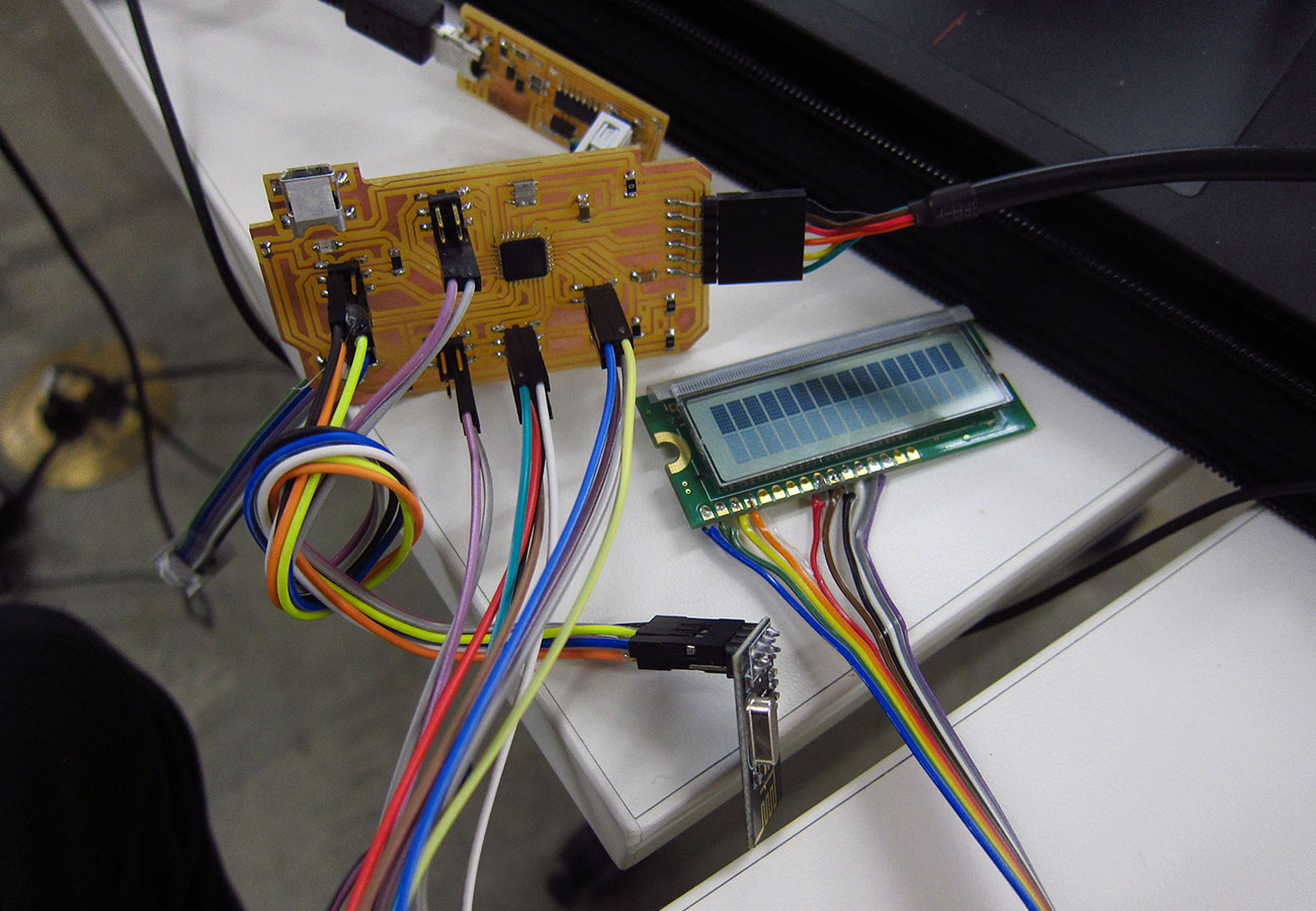
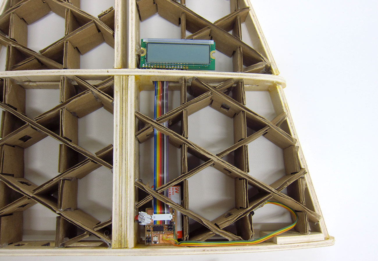
The electronics design component of this project is a circuit which reads voltage from a temperature sensor and prints the converted value to an LCD screen. I originally produced a mash-up board of the helloTemp and helloLCD and was able to print values gathered from the NTC thermistor to the LCD screen. However, I was only getting an ADC value and when I tried to use the conversion code that exists in the helloTemp python program, my numbers give a general pattern either increasing or decreasing upon touching the sensor, but they were inconsistent and did not represent a Celsius value which was the intention. I struggled with this for quite a while and came to the conclusion that I do not understand the proper variable types that I should be using in order to get the conversion from ADCL and ADCH to Celsius. I needed to make further progress, so I switched from the NTC thermistor to a TMP36 temp sensor which provides a voltage output that is linearly proportional to the Celsius temperature without requiring any external calibration. Once I had this working I wanted to send the temp sensor value using the nrf24 module with the idea that another surfer with a reciever board could tune to your channel and get water temperature. I was able to get the sender and receiver boards to communicate and read the temp value, but my trouble occured when trying to attach the LCD to the reciever board. I mapped the pin setup that I was using for the helloLCD board but I was never able to get any characters to print, only solid rectangles. As my time was running thin, I reverted back to the helloLCD board and soldered some ribbon wires to VCC, ground, and Pin6 to read the signal from the TMP36. This worked perfectly and was able to satisfy my minimum viable product.