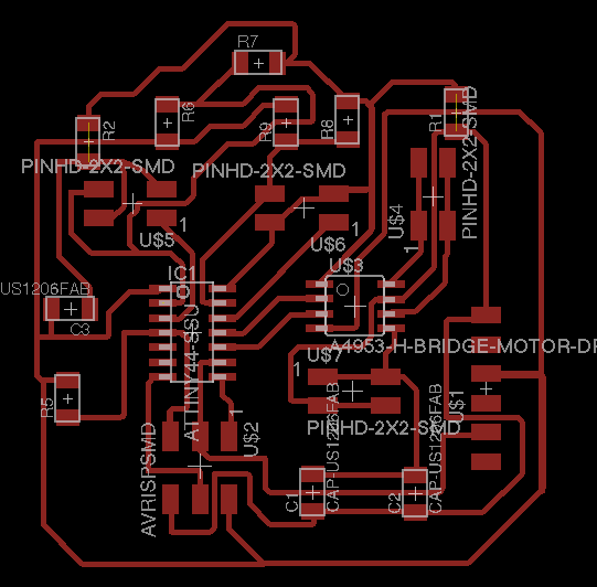
and my traces, with two jumper resistors to avoid drilling holes in my board:
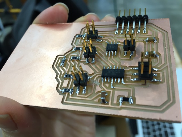
printing the board was more of a headache than it should have been! my design was pretty big so i had to be careful about the orientation of my 2x3 pcb. it took me some time to realize that the size preview on fabmodules is horizontal by vertical, like printing paper but it had been so fixed in my mind that it should be vertical by horizontal (like matrices!).
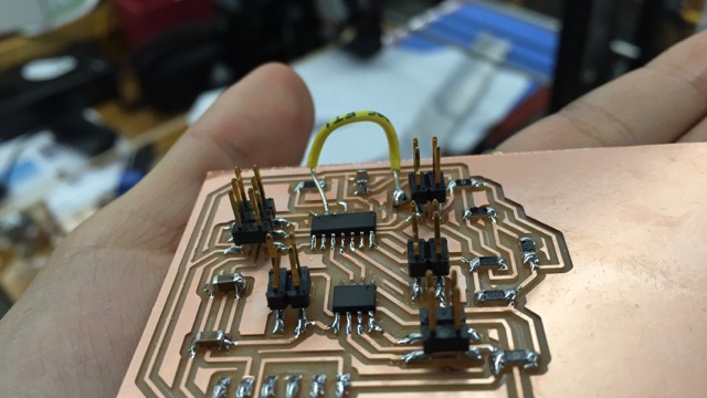
anyway, i eventually succeeded in printing and stuffing my board:
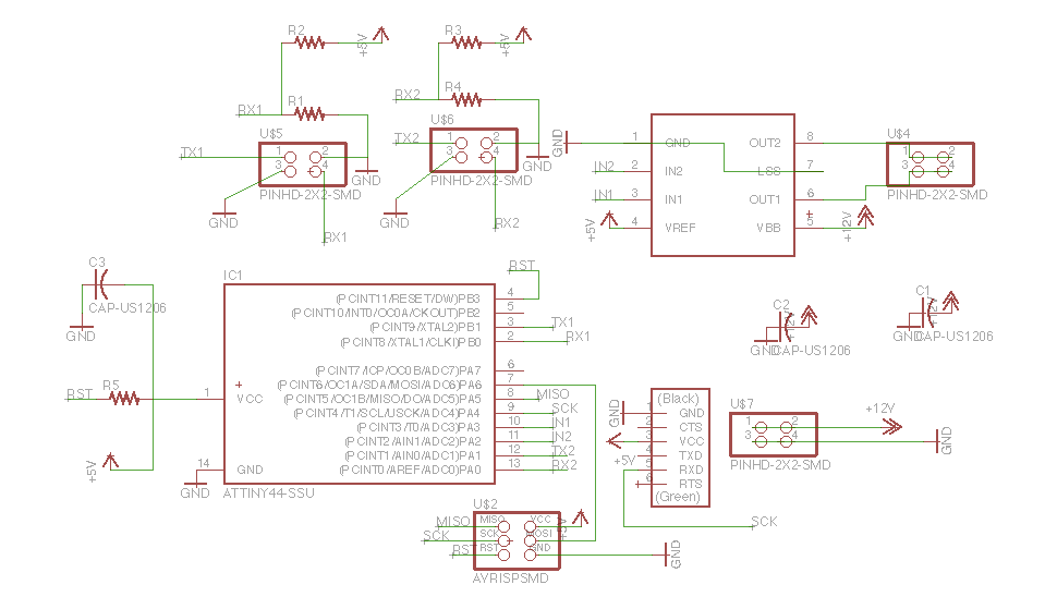
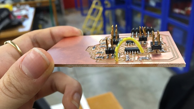
but rob explained to me later that only the PA0-PA7 ports on the attiny44 can be programmed to receive analog signals (and also how that is done through MUX settings). i had one of the rx pins connected to a PB port but the fix was easy: i cut the line with a knife and soldered a little wire bridge to make an appropriate connection:
in the code, i alternated between the MUX settings for one rx port and the other within the while loop and sent all values to be read in the interface (see next week's interface and application programming).
the two step response devices working side by side:
video
as a simple start, i placed rubbers between the copper sheets and programmed the motor to turn on when the designated step response senses a greater force than the other and to stop otherwise. here's the set-up:
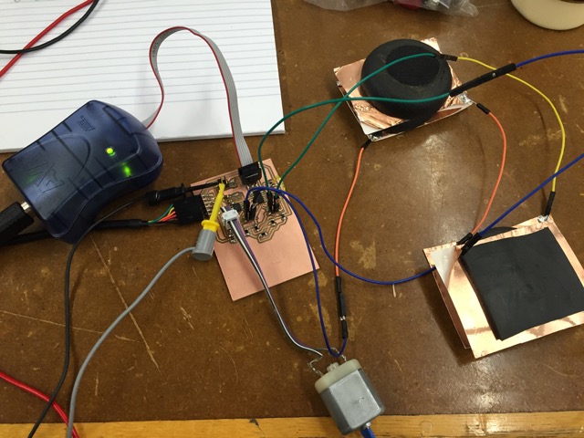
and video (link to dropbox). notice that the change in the bars on the interface are barely perceptible at this distance between the copper sheets although the magnitudes do change considerably.