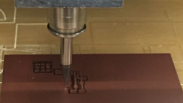
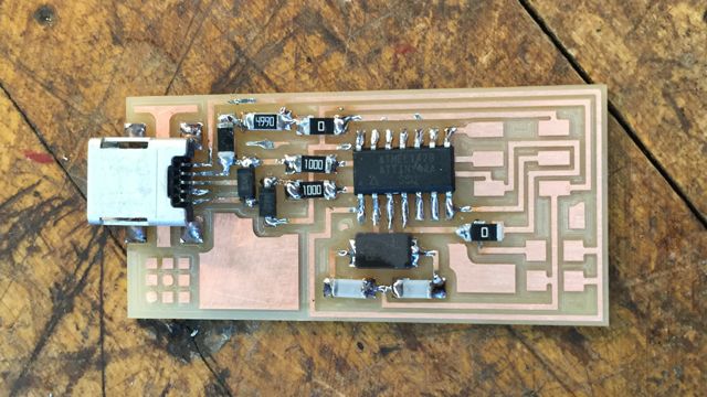
i milled my printed circuit board according to the trace and interior templates given but unfortunately the settings seemed to be a little off although i had loaded the correct ones. there was residual copper between the offsets and i feared that either the machine wasn't cutting deeply enough or that there was another parameter off. my first card ended up like this:
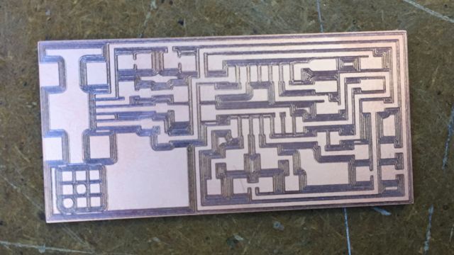
a few boards lying around had the same problem, but only partially on the board, so it seems maybe that our taping job wasn't smooth and flat enough or the sacrificial layer suffered damage enough that the normal cut depth becomes insufficient. cutting with .2mm depth instead of .1mm, however, solved the problem. i later found out that the most likely problem was actually a broken screw that remained loose.
i don't have any pictures of soldering in action unfortunately because my both hands were occupied. next time, for better documentation, perhaps i could ask a buddy to snap a few shots. i believe my documentation is missing the snazziest part!
i didn't quite follow the inside-to-outside order because i wanted to tackle the two most challenging pieces first (and also because i forgot). i soldered very carefully each leg/tooth one by one, brushing away any solder meddling in between with my solder wand, which seemed to work out. this way i didn't use the copper braid method (flooding a tight spot with solder and using copper braid to remove excess solder) because i was rather maladroit with the removal step. next time i work on this though, i will try again to tame the copper braid.
more messy progress... this is so much fun!
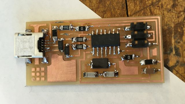
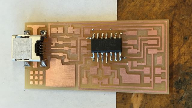
and the complete board! now to make my ribbon cable (i kept thinking it was called a "rainbow cable" haha!) connecting that lil guy to an existing FabISP programmer:
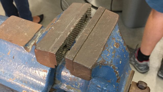
oops. i had to chop off this head that i had crushed. sorry, clearly i sometimes cannot control my strength. just kidding, i used the wrong vise:
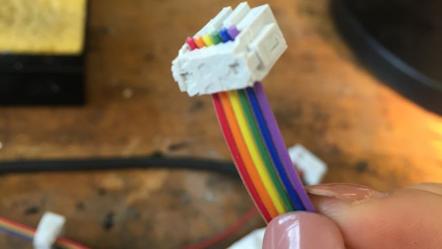
what a monster! here is the finished piece with healthy heads snapped in place:
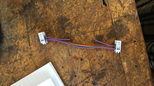
i should have probably bent the cable closer to the ends...
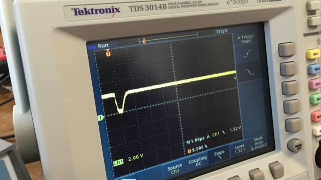
the final step is to program my board. "make fuse" and "make program" both resulted in success messages yet my board is not recognized as a USB on the computer. i did a complete check for overlapping connections, checked voltage and resistance, and fixed up some "cold" solder joints, but to no avail. Rob helped me try to debug: the crystal clock was at the correct frequency and the signal displayed on the oscilloscope is similar to that of Nils' working board:
a potential next step is to remove, possibly replace, and resolder the microcontroller and the USB connector. but i think i will just redo this week's project and try to get a working programmer in preparation for electronics design in two weeks! i am quite thankful for this buffer period...
also, i understand very little of how all of this works. hopefully in some time, i will be able to demystify each piece and interaction.
but now onward to 3D scanning and printing!