Week 2: Electronics Production
Fab ISP In-Circuit Programmer
Fall 2015
What is this in-circuit programmer of which we speak? Wikipedia has a few things to say about “programmer (hardware)”: “Usually device programmers are connected to a personal computer through a printer connector, USB port or LAN interface. A software program on the computer then transfers the data to the programmer, selects the circuit and interface type, and starts the programming process.” This project took a few days, mostly because my soldering skills would have made even Mr. Bean or Inspector Clouseau of the Pink Panther wince. At any rate, persistence mostly prevailed. Here are some breadcrumbs as to how I did it. Enjoy! Overall project flow as described at http://academy.cba.mit.edu/classes/electronics_production/index.html
Make the board: http://academy.cba.mit.edu/classes/embedded_programming/hello.ISP.44.interior.png Look at the components: http://academy.cba.mit.edu/classes/embedded_programming/hello.ISP.44.components.png Use the traces: http://academy.cba.mit.edu/classes/embedded_programming/hello.ISP.44.traces.png Use the outline: http://academy.cba.mit.edu/classes/embedded_programming/hello.ISP.44.interior.png
Use firmware (see comment below)
Solder on the components. Check that solder didn't go where it wasn't supposed to and that there is continuity, that the difference between ground and the power is 5 volts right as it comes out of the USB connecting to your computer and 3.3 volts after it's been through the diodes in your set up.Program it!
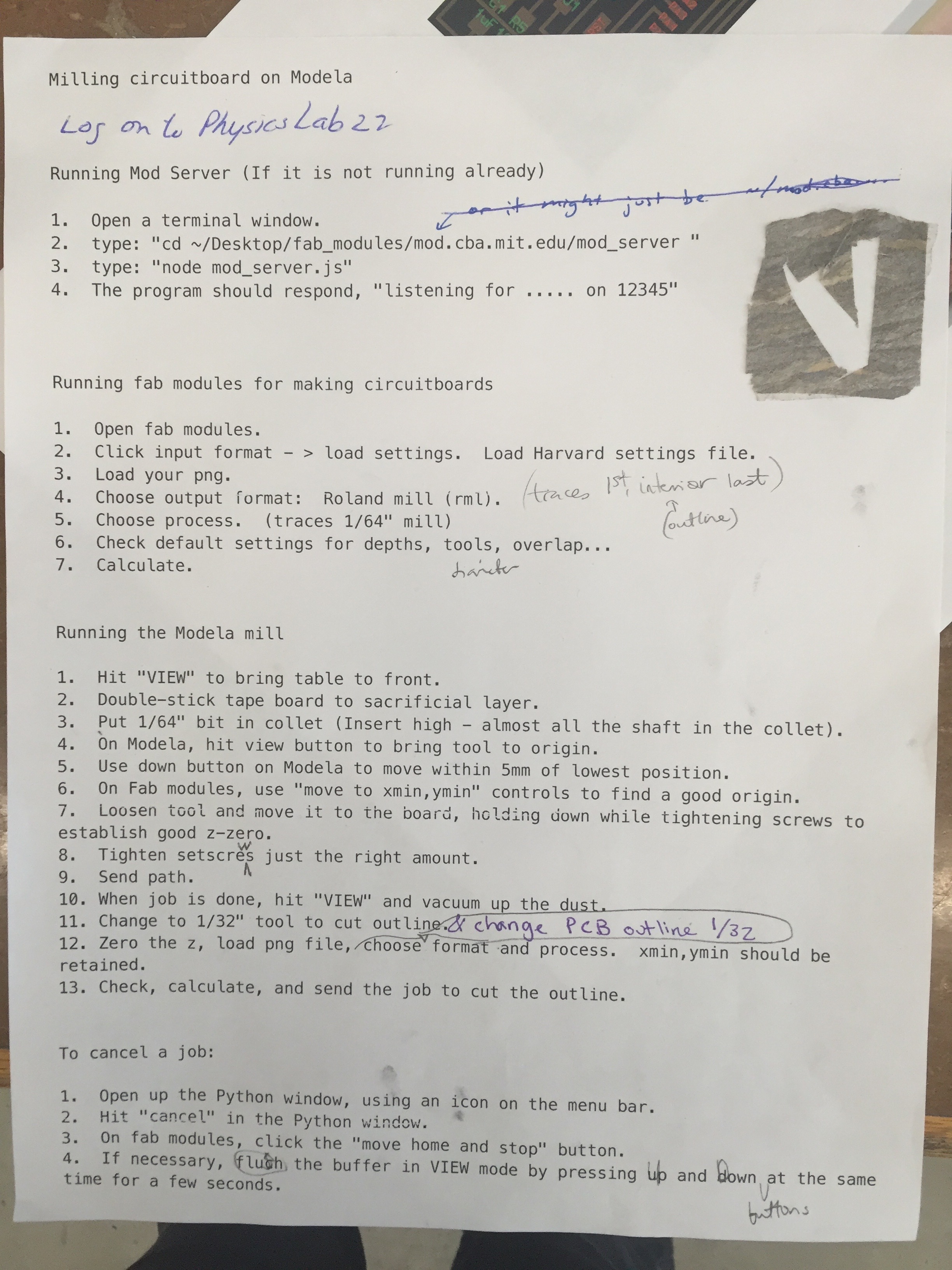
put in the USB power type into the Terminal (on the computer you're connecting your newly made creation with a USB cord): make clean make hex (sudo) make fuse (check programmer in Makefile, may need to repeat) (sudo) make program Last bit of hardware work desolder SJ1 and SJ2 make IDC ISP cable, connecting header pin 1 to pin 1, check wiresInstructions for Roland milling part of it (refer to the links in the excerpt above for the actual image files for the board, traces, and interior of the circuit design)
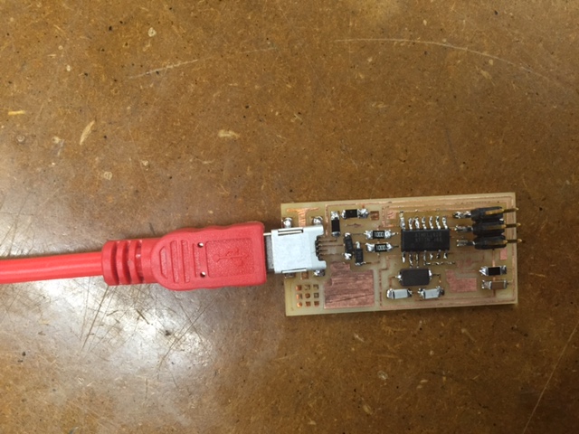
 This is what I ended up creating! Hooray!
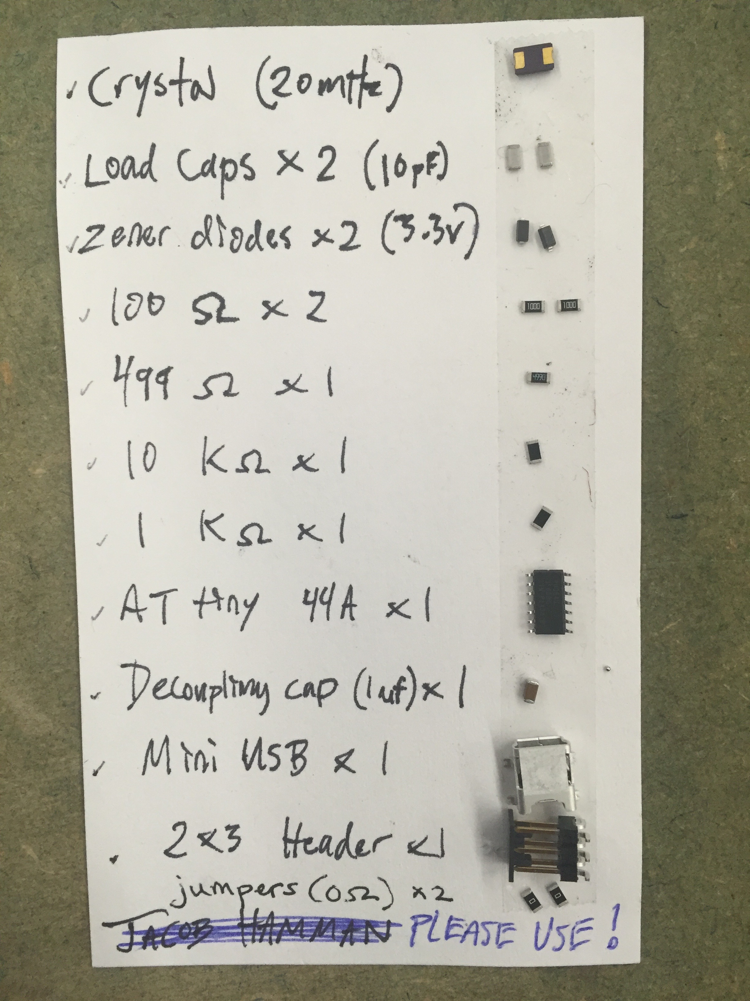
 Next up was putting on the components. Here is the components ingredient list:
 Soldering tips: use double sided tape to hold down the circuit and keep it still, do your soldering under a microscope so you can see what you’re doing, put a bit of solder on the target area before you put down the component. Once the component is down, place the soldering iron and the wire (solder) near but not touching the component or each other. Wait for things to heat up and soon they will start flowing in a beautiful stream of silvery goo. If it takes you a lot of practice to be able to do this consistently, we’re in the same club.
The finished product for the hardware looked like this (once a FabISP cable was plugged in). Hooray!
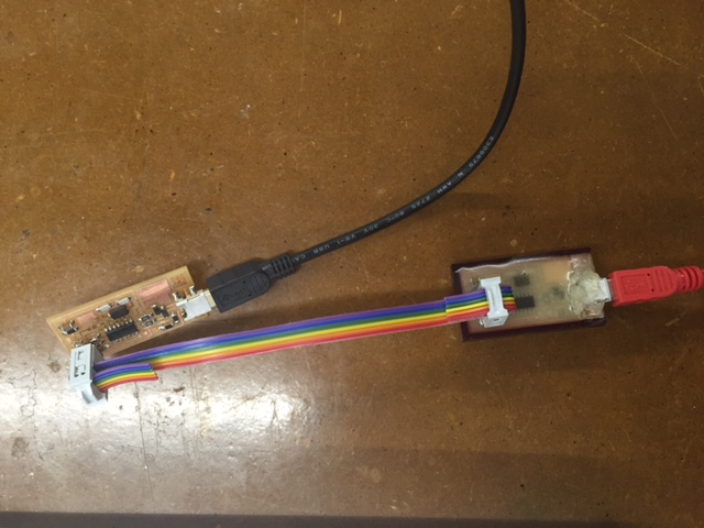 Hooray!
But then, connecting it to the computer and trying to program it…not so hooray. I (and others in lab at the same time) got the same error message: “Did not find any USB device”
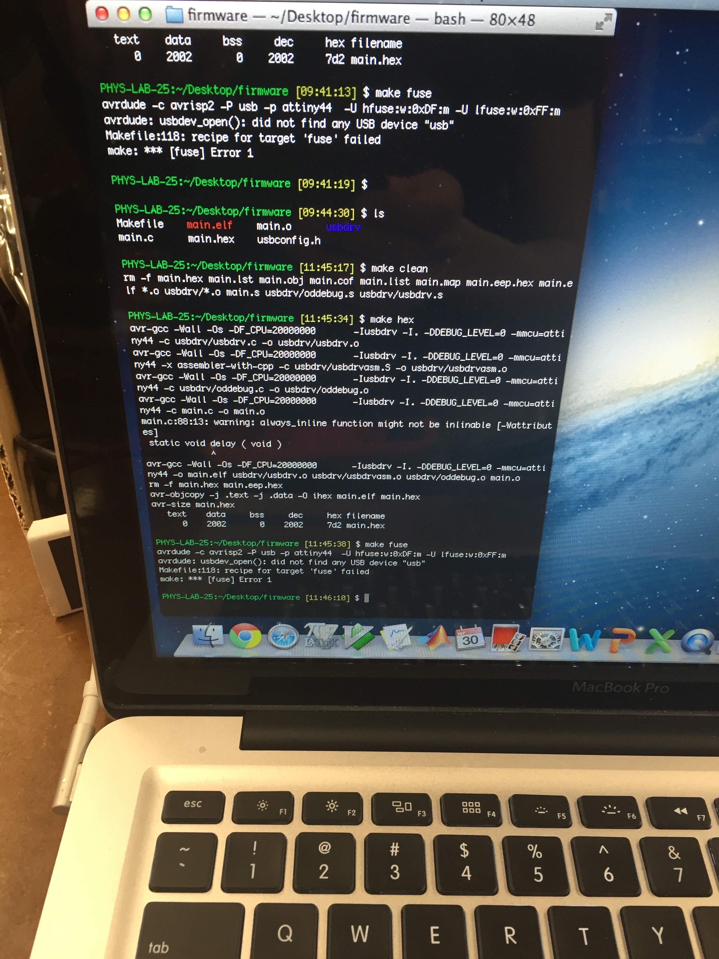 Glenn Bogardis wrote this follow up to the same problem I was having:
It needed a different firmware package. This is the correct_firmware
“Additionally, a mistake I was making last night was to have my board plugged into the computer while the programmer was plugged into the charger – this is the reverse of how it should be, the programming board needs to be plugged into the computer.
Also, make sure you’re plugging in the 6-pin connecting cables in the same orientation, not in mirror orientation (which is tempting to do because of the design of the cable). “
Then…with the correct firmware, you’d think that there would be magic!
No.
Let’s talk about the debugging process…
The voltmeter provided insight (as did Tiffany Cheng–thank you!) into the fact that power was not flowing from the computer through the usb and into the board: the voltmeter did not detect a 5v difference between the pins on either side of the usb as it should have. With the microscope, I discovered that one of the pins on the usb was basically hanging in midair and not actually touching the wires below it. So, I resoldered that pin and, voila!, the voltmeter detected a differential across the USB pins.
Then, I made my big mistake of the night.
I was checking the board with the voltmeter — just some final checks before programming it. All seemed good! I wanted to take an awesome, victorious photo with the voltmeter touching the newly created board, so I placed the two points lovingly on random sides of the board. Pfzzz!! Sizzle! Phfoo! Smoke and a crunch. Yup, I shorted it. In my moment of glory. Fail.
Daniel Windham pointed out that the attiny44a was probably the culprit; it’s small, complex, and sensitive to small current differentials. I’d likely connected two parts of the board that ordinarily should be protected by a resister in between them, but by connecting them, I’d driven 5v through an area that was only prepared to handle far less. This was further confirmed when I plugged in my laptop, and I got this error message:
 That is Macbook Pro for “you have a short in your board and I am going to protect you foolish human by disconnecting from this dangerous USB”. In hindsight, I should never have connected that, it was just a case of "I've been here too long, and now I'm going to do random things and hope something works'".
So, I replaced the attiny44a. Then, there was another issue when I checked the connections on the board with the voltmeter. I noticed that there was no current flowing through one of the pins and a wire on the 2×3 head fabisp connector. So, I replaced that, too.
Back to the present: At this point, I cannot not find any shorts with the multimeter. Yet, it still errors out when I try to program it. It even has the gall to put out this error: “”initialization failed, rc=-1 double check connections and try again, or use -F to override this check. done. Thank you. *** [fuse] Error 1″
“Thank you”…really? No, no thank you.
Print out from the terminal is below, with the charming error
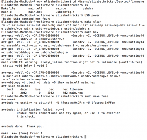 But then…Rob came in with a bold suggestion, the kind of risky, unprecedented, Hail Mary pass of an idea that just might work: connect to the power source.
Yeah. In my excitement, I neglected to provide my board with a source of its own power...
After getting over my embarrassment (and actually plugging it in this time), I re-ran the instructions from the command line. Then, I checked in my About this Mac preference to confirm that it was detecting the USB. Finally, I just needed to de-solder the jumpers from it:
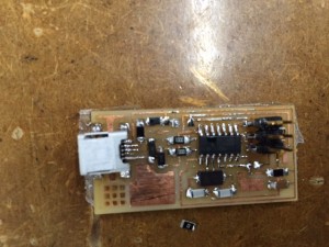 Here ends the ballad of the creation of my first FabISP in-circuit programmer!