Building the FabFTDI
Introduction
FabFTDI is a DIY replacement for FTDI cables that can be fabricated in fablab. It uses V-USB for software-only implementation of a low-speed USB device and is based on V-USB CDC example. FabFTDI support baud rate from 1200 - 4800.
Schematic Diagram
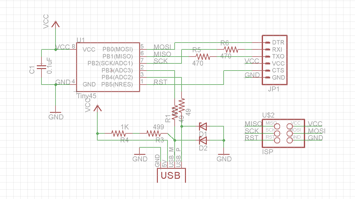
The figure above shows the schematic diagram of the FabFTDI circuit. The circuit is powered by a USB port and can provide 5V voltage and up to 500mA current.
A USB port has four lines: 5V, D-, D+ and GND. The line D- and D+ are called data lines and used to for communication. These data lines can tolerate only upto 3.3V voltage, and therefore, two Zener diodes are used to limit the voltage to 3.3V. The line D- is connected to 5V using 15k (10kohm + 499ohm) which is used by the host (your computer) to determine that the connected device is a low speed device. Resistors R5 and R6 are used to protect TxD and RxD pins.
Board Design
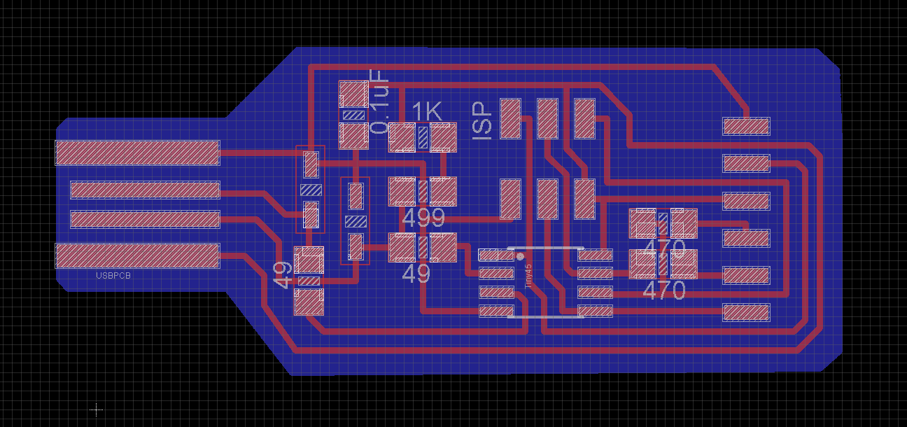
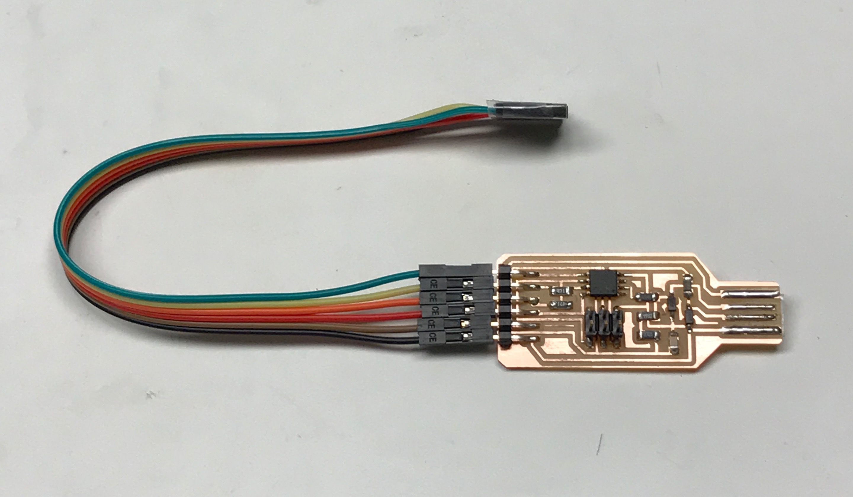
Use the above image as a guideline for solder components.
If you would like to edit original eagle files, here is the link for the schematic and board files.
PCB Fabrication and Assembly
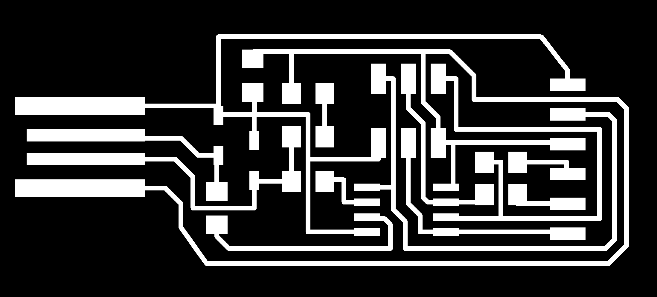
- Download the PNG files for trace and board outline from links below -
- Use the standard PCB milling process to fabricate PCB.
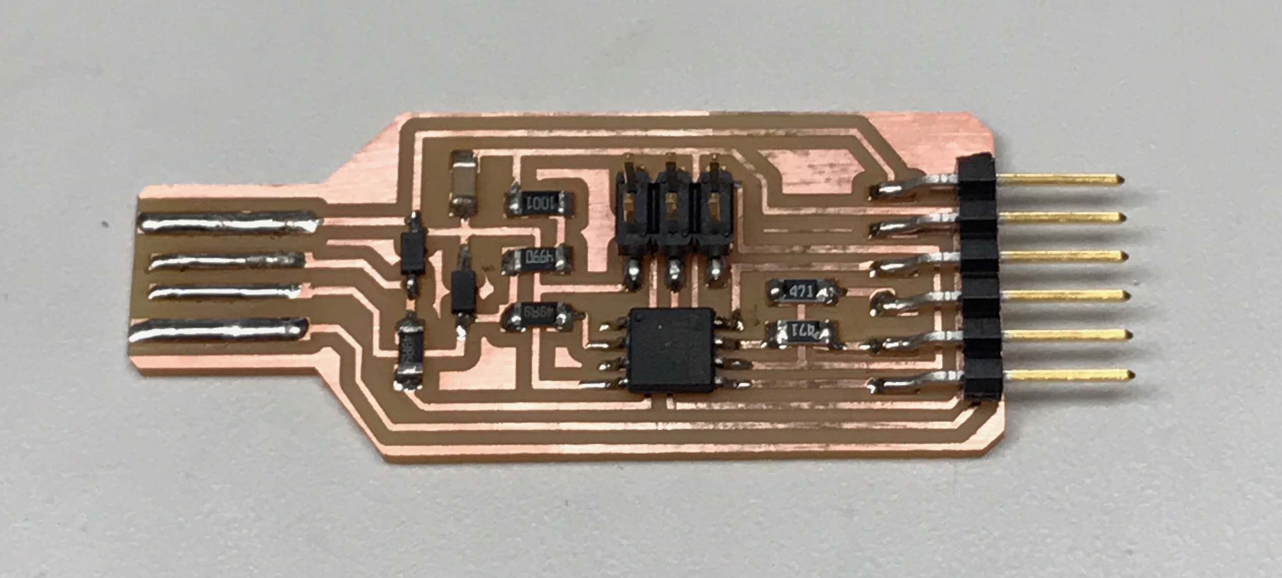
- You will need following components: Attiny45, two 3.3V Zener diode, 0.1uF capacitor, two 49ohm resistors, two 470ohm resistors, 1K resistor, 499ohm resistor, 2x3 pin header and 1x6 pin header.
- Make sure to solder zerner diode in the right orientation. The anode (A) should be connected to GND and cathode (C) should be connected to D- or D+.
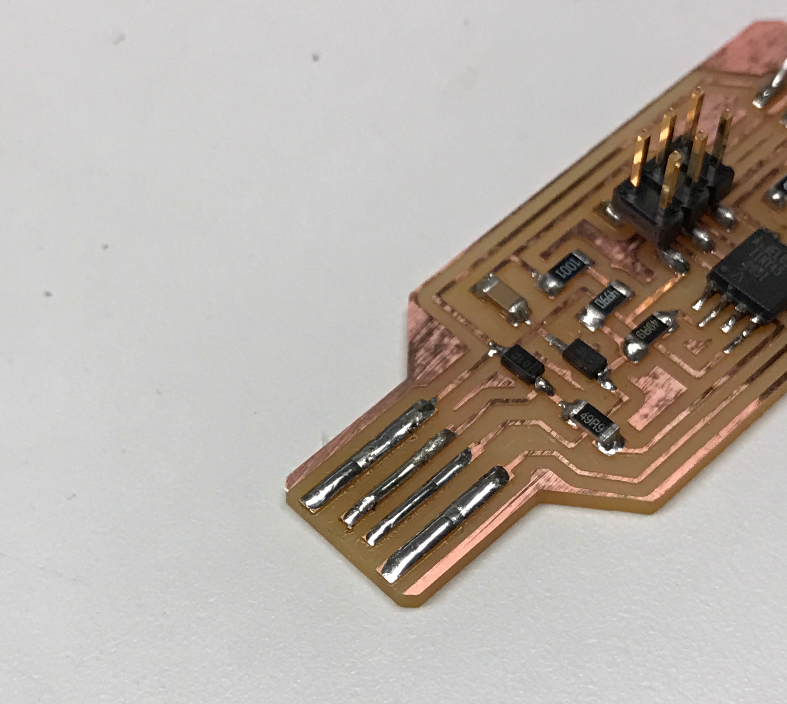
- If there is any access copper left in front of the middle two pads of USB footprint in the board, remove it using a knife and apply some solder to all the pads of USB lines as shown below-
Flash Firmware
- Download the firmware file from here. Flash it using the following command (replace avrisp2 with usbtiny if you are using fabisp)
sudo avrdude -p t45 -c avrisp2 -P usb -U flash:w:cdctiny45.hex:i
- Flash fuses using following commands
- sudo avrdude -p t45 -c avrisp2 -U lfuse:w:0xF1:m
- sudo avrdude -p t45 -c avrisp2 -U hfuse:w:0xCE:m
- sudo avrdude -p t45 -c avrisp2 -U euse:w:0xFF:m
Note that the current version of firmware does not support hardware flow control using RTS/CTS. If you would like to edit the firmware, here is the link to original files.
Testing your FabFTDI
- Connect your FabFTDI to a computer. Mac/Unix operating system should be able to detect it without any driver. For Windows, download driver from here.
- For testing FabFTDI, we will use Neil's hello.ftdi.44.echo board. Since our cable support baud rate up to 4800, we need to specify this baud rate in hello.ftdi.44.echo.c file. Open this file and change bit_delay_time = 208.3, compile and flash it into hello.ftdi.44.echo board.
- Next step is same as what you did in Embedded programming week. Connect FabFTDI to hello.ftdi.44.echo and execute command
python term.py /dev/ttyACM0 4800
if you can see the typed character in term.py window echo'ing back then you have a working FabFTDI. Congratulations!!
Troubleshooting
If things don't workout, try following things
- Double check the polarity of the two Zener diodes.
- Consider using other USB port on your computer.
- Check if the FabFTDI is connected in the right orientation. Match GND pin of FabFTDI to GND pin of hello.ftdi.44.echo board.
- Make sure FabFTDI is plugged-in properly and not loose.

This work is licensed under a Creative Commons Attribution-ShareAlike 4.0 International License.