FabISP: Programming
- To program the FabISP, you first need to install the necessary software for your operating system and download the firmware.
- Then you edit the Makefile
- Set the fuses / program the board
- Verify that the board is working properly
- Then you need to open up the jumpers to make it a programmer.
Install Necessary Software for AVR Programming:
For the electronics units in the Fab Academy, you will need:
- Avrdude (for programming AVR microcontrollers)
- GCC (to compile C code)
Jump to the instructions for your Operating System:
Ubuntu Software Install
Get and install avrdude / GCC software and dependencies:
Open Terminal and type:
sudo apt-get install flex byacc bison gcc libusb-dev avrdudeThen type:
sudo apt-get install gcc-avr- type "y" when asked to do so by your system
Then type:
sudo apt-get install avr-libcThen type (may already be installed):
sudo apt-get install libc6-dev
Download and Unzip the Firmware:
Move to the desktop
cd ~/Desktop
Download the firmware from the Fab Academy Electronics Production page.
wget http://fab.cba.mit.edu/classes/863.16/doc/tutorials/fabisp_programming/fabISP_0.8.2_firmware.zip
Unzip the firmware
unzip fabISP_0.8.2_firmware.zip
Mac OS Software Install
Get and install avrdude / GCC software and dependencies:
- Download and Install Crosspack AVR - Has an installer.
- Get Make (via XCode):
- If you are running Lion or higher - you can download XCode from the Apple App store.
- If you are running a pre-Lion OSX - Get the install disks that came with your mac and install the developer tools.
Download the firmware (right click on the link below and save it to your desktop):
Open terminal navigate to the desktop:
cd ~/Desktop/
Unzip the fabISP_0.8.2_firmware.zip directory:
unzip fabISP_0.8.2_firmware.zip
Move into the newly created firmware directory on your desktop
cd ~/Desktop/firmware
Windows Software / Drivers Install
Get and install avrdude / GCC software and dependencies and drivers:
- Warning, WinAVR is abandoned.You can use the installer, but before you start, take note of your current system path.
Installing it can destroy your systems path variable! - Furthermore, WinAVR may require additional packages to function on Windows 10. (Some programs are broken and do not run.) avr-gcc and other development tools can be installed in the Bash on Ubuntu on Windows 10 environment, follwing the same instructions as Ubuntu. However, I don't think a working avrdude can be installed this way. Using a Linux machine (or a Linux virtual machine) might be the easiest option for Windows 10 users right now. (If you have discovered better ways to make this work, please update this documentation!)
- Download and Install WinAVR - Has a (broken) installer.
- Here is a step-by-step set of instructions
- After installing check your systems path variable, if it only contains the path to the winavr installation:
- copy those values
- restore your old path
- add the windavr path back to it
- close any commandprompt window you may have open
- Download the drivers for your version of Windows
- Download the FabISP Firmware
- Plug in another FabISP or USBtiny programmer.
- Install the drivers:
Go to the Start menu -> Control Panel -> Device Manager (or run "mmc devmgmt.msc")- Locate "FabISP" under "Other Devices"
- Right click on the "FabISP"
- Select "Update Driver Software.."
- Select "Browse my computer"
- Navigate to the drivers folder you downloaded at step 4 and click on the folder.
- Hit "ok" to install the drivers for the USBtiny / FabISP
Power the FabISP Board
The board needs power:
- Make sure that the mini USB connector for the FabISP you are trying to program is plugged into your computer.
- AND that a separate pogramer is plugged in to the 6-pin programming header. (this could be another working FabISP or the ATAVRISP2, a USBtiny, an AVR Dragon, etc.)

If you are using the ATAVRISP2 programmer, you can skip step 7, you do not need to edit the Makefile, it is already set up to work with the ATAVRISP2 If you are using another programmer you will need to edit the Makefile.
Helpful ATAVRISP2 Programmer Light Indicator Messages
If you are using the ATAVRISP2 programmer only. If you connect the programmer to the 6-pin programming header on your FabISP board and you get:
- Green Light: means that the header is soldered correctly, the board is getting power.
- Yellow Light: means that the board is getting power, but most likely the 6-pin programming header is not soldered correctly (re-flow your solder joints / check for cold joints, check for shorts).
- Red Light: means that the board is not getting power - check for shorts.
Edit the Makefile
The Makefile is in the firmware directory that you downloaded. The Makefile is set up to work with the AVRISP2 by default. If you are using another programmer, you will need to edit the Makefile.
Ubuntu:
nano Makefile
Mac:
Open the Makefile with TextEdit.
Windows:
Open the Makefile with Notepad++.
Make Changes - All OS:
A window will open containing the Makefile. Go to the line that says:
#AVRDUDE = avrdude -c usbtiny -p $(DEVICE) # edit this line for your programmer
AVRDUDE = avrdude -c avrisp2 -P usb -p $(DEVICE) # edit this line for your programmer
- If using the USBtiny programmer or another FabISP
- Remove the "#" in front of the line with "usbtiny" in it
- Add a "#" to beginning the line with the "avrisp2" in it to comment it out.
- save the MakefileProgram the FabISP (All OS):
Navigate to the directory where you saved the FabISP firmware. If you followed the instructions above, this will be the desktop.
Open your terminal / command line interface and move to the firmware directory.
Ubuntu / Windows type:
cd Desktop/firmware
For Mac users who downloaded the modified firmware:
cd Desktop/fabISP_mac.0.8.2_firmware
Next you need to compile the firmware.
Type:
make clean
If you are successful - you will see this response from the system:akaziuna@Titan:~/Desktop/firmware$ make clean
Type:
rm -f main.hex main.lst main.obj main.cof main.list main.map main.eep.hex
main.elf *.o usbdrv/*.o main.s usbdrv/oddebug.s usbdrv/usbdrv.smake hex
If you are successful - you will see this response from the system:
akaziuna@Titan:~/Desktop/firmware$ make hex
avr-gcc -Wall -Os -DF_CPU=20000000	 -Iusbdrv -I. -DDEBUG_LEVEL=0
-mmcu=attiny44 -c usbdrv/usbdrv.c -o usbdrv/usbdrv.o
avr-gcc -Wall -Os -DF_CPU=20000000	 -Iusbdrv -I. -DDEBUG_LEVEL=0
-mmcu=attiny44 -x assembler-with-cpp -c usbdrv/usbdrvasm.S -o usbdrv/usbdrvasm.o
avr-gcc -Wall -Os -DF_CPU=20000000	 -Iusbdrv -I. -DDEBUG_LEVEL=0
-mmcu=attiny44 -c usbdrv/oddebug.c -o usbdrv/oddebug.o
avr-gcc -Wall -Os -DF_CPU=20000000	 -Iusbdrv -I. -DDEBUG_LEVEL=0
-mmcu=attiny44 -c main.c -o main.o
avr-gcc -Wall -Os -DF_CPU=20000000	 -Iusbdrv -I. -DDEBUG_LEVEL=0
-mmcu=attiny44 -o main.elf usbdrv/usbdrv.o usbdrv/usbdrvasm.o usbdrv/oddebug.o
main.o
rm -f main.hex main.eep.hex
avr-objcopy -j .text -j .data -O ihex main.elf main.hex
avr-size main.hex
   text	   data	    bss	    dec	    hex	filename
      0	   2020	      0	   2020	    7e4	main.hex
Next, you need to set the fuses so your board will use the external clock (crystal)
Type:
make fuse
If you are successful - you will see the following response from the system:akaziuna@Titan:~/Desktop/firmware$ sudo make fuse avrdude -c usbtiny -p attiny44 -U hfuse:w:0xDF:m -U lfuse:w:0xFF:m avrdude: AVR device initialized and ready to accept instructions Reading | ################################################## | 100% 0.01s avrdude: Device signature = 0x1e9207 avrdude: reading input file "0xDF" avrdude: writing hfuse (1 bytes): Writing | ################################################## | 100% 0.00s avrdude: 1 bytes of hfuse written avrdude: verifying hfuse memory against 0xDF: avrdude: load data hfuse data from input file 0xDF: avrdude: input file 0xDF contains 1 bytes avrdude: reading on-chip hfuse data: Reading | ################################################## | 100% 0.00s avrdude: verifying ... avrdude: 1 bytes of hfuse verified avrdude: reading input file "0xFF" avrdude: writing lfuse (1 bytes): Writing | ################################################## | 100% 0.01s avrdude: 1 bytes of lfuse written avrdude: verifying lfuse memory against 0xFF: avrdude: load data lfuse data from input file 0xFF: avrdude: input file 0xFF contains 1 bytes avrdude: reading on-chip lfuse data: Reading | ################################################## | 100% 0.00s avrdude: verifying ... avrdude: 1 bytes of lfuse verified avrdude: safemode: Fuses OK avrdude done. Thank you.
Next you want to program the board to be an ISP.
Then type:
make program
If you are successful - you will see the following response from the system.akaziuna@Titan:~/Desktop/firmware$ sudo make program [sudo] password for akaziuna: avrdude -c usbtiny -p attiny44 -U flash:w:main.hex:i avrdude: AVR device initialized and ready to accept instructions Reading | ################################################## | 100% 0.01s avrdude: Device signature = 0x1e9207 avrdude: NOTE: FLASH memory has been specified, an erase cycle will be performed To disable this feature, specify the -D option. avrdude: erasing chip avrdude: reading input file "main.hex" avrdude: writing flash (2020 bytes): Writing | ################################################## | 100% 5.68s avrdude: 2020 bytes of flash written avrdude: verifying flash memory against main.hex: avrdude: load data flash data from input file main.hex: avrdude: input file main.hex contains 2020 bytes avrdude: reading on-chip flash data: Reading | ################################################## | 100% 3.36s avrdude: verifying ... avrdude: 2020 bytes of flash verified avrdude: safemode: Fuses OK avrdude done. Thank you. avrdude -c usbtiny -p attiny44 -U hfuse:w:0xDF:m -U lfuse:w:0xFF:m avrdude: AVR device initialized and ready to accept instructions Reading | ################################################## | 100% 0.01s avrdude: Device signature = 0x1e9207 avrdude: reading input file "0xDF" avrdude: writing hfuse (1 bytes): Writing | ################################################## | 100% 0.00s avrdude: 1 bytes of hfuse written avrdude: verifying hfuse memory against 0xDF: avrdude: load data hfuse data from input file 0xDF: avrdude: input file 0xDF contains 1 bytes avrdude: reading on-chip hfuse data: Reading | ################################################## | 100% 0.00s avrdude: verifying ... avrdude: 1 bytes of hfuse verified avrdude: reading input file "0xFF" avrdude: writing lfuse (1 bytes): Writing | ################################################## | 100% 0.00s avrdude: 1 bytes of lfuse written avrdude: verifying lfuse memory against 0xFF: avrdude: load data lfuse data from input file 0xFF: avrdude: input file 0xFF contains 1 bytes avrdude: reading on-chip lfuse data: Reading | ################################################## | 100% 0.00s avrdude: verifying ... avrdude: 1 bytes of lfuse verified avrdude: safemode: Fuses OK avrdude done. Thank you.Wooo! Success!
Errors
- If you get errors - read the errors and follow instructions.
- If avrdude cannot connect to your board's microcontroller - you should follow the "Troubleshooting Short Circuits" instructions and ask your instructor for help.
To Verify That Your ISP is working correctly:
Ubuntu:
Type:
lsusb
If your FabISP has been successfully programmed, you should see a list of the USB devices plugged into your computer. The FabISP will be listed in a line like the following:Bus 002 Device 004: ID 1781:0c9f Multiple Vendors USBtiny
Mac:
Go to the System Profiler > Hardware > USB > Hub:
Step - By - Step:- Click the "apple" menu in your main toolbar
- Select "about this mac"
- Select "more info"
- Under the "Contents" menu in the left hand navigation
- Click "Hardware" to expand the hardware menu (if not already expanded)
- Click "USB"
- Under the "USB Device Tree"
- Click "Hub" to expand the hub menu (if not already expanded)
- "FabISP" should be listed in the hub menu - Your FabISP device has been successfully programmed and is recognized by your computer.
Windows:
Go to the Start Menu > Hardware and Sound. The FabISP should be listed.
After You Have Programmed the Board:
Remove the 0 ohm resistor and solder bridge as shown in the picture below. Now you can use it as a programmer to program other boards.

Notes on USB and Timing
The USBtiny (on which the FabISP is based), the original FabISP, and all of the many variants and improvements use a library called V-USB to handle the USB communication. USB is a fairly complex protocol, and usually is implemented with dedicated hardware on a microcontroller with USB support. V-USB implements USB entirely in software, which enables USB on practically any AVR microcontroller just using the GPIO pins. The timing requirements are met by using hand-optimized assembly code.
V-USB works incredibly well, considering how much of a hack it is. However, USB still has fairly stringent timing requirements in order to work properly. V-USB implements a low-speed USB device, with signaling at 1.5 MHz, which is the least demanding type of USB device. However, if the timing is too far off, this can cause USB communication problems.
Over the years, many people have iterated on the FabISP design to reduce the component count, use cheaper components, and use more readily available values. For example, a ceramic resonator isn't something you'd usually find on a microcontroller that's speaking USB, since the frequency might be too inaccurate for reliable communication. Yet several FabISP designs use ceramic resonators, and appear to work. This raises questions about how far tolerances can be stretched before a programmer is no longer a reliable USB device. As USB ports get faster and faster, USB controllers can also be less tolerant of timing and frequency variations.
To investigate whether some of the FabISP designs have deviated far enough from the USB spec to start causing widespread problems, I probed several different FabISP variants with a high-speed oscilloscope. The results are below.
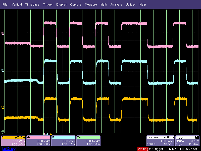
The oscilloscope capture shows the differential USB signals from three different FabISP variants. The vertical lines are a 3MHz reference clock. Since low-speed USB signaling occurs at 1.5MHz, each bit should last for two vertical lines. If the timing is accurate, the transitions should happen right on the lines, not before or after.
These captures show the beginning of a packet on the USB bus, sent from the FabISP to the computer. This starts with a synchronization sequence (the high/low/high/low/high/low pattern) followed by four bits identifying the type of packet (in this case, it's an acknoweldgement from the FabISP that the last message from the computer was received).
The three traces, from top to bottom, are:
- An original FabISP, which uses a 12MHz crystal. The 12MHz crystal can be divided evenly down to the low-speed USB 1.5MHz clock. All of the bit transitions occur precisely in sync with the reference.
- A FabISP built with a 20MHz crystal instead. 20MHz is a more standard part in the fab inventory, but it does not divide evenly down to 1.5MHz (there's a third of a cycle left over.) This introduces a little bit of jitter; some of the signal edges are just a little bit late or early. The average frequency is still accurate, but the jitter reduces the tolerance for frequency error just a bit.
- A FabISP built with a 20MHz resonator. In addition to the jitter due to the non-integer clock divisor, resonators are not quite as accurate as crystals in terms of the frequency they generate. This can be seen particularly at the last bit on the screen, where both edges are now late. Over many bits, this error can accumulate.
The transitions for the original FabISP, which used 49Ω bus termination resistors, are noticeably faster and more square. In later designs, the termination resistors changed to 100Ω for some reason, leading to the more rounded edges.
Conclusions
While the timing has gotten measurably worse from the original 12MHz design, the current 20MHz crystal versions shouldn't cause any problems. Crystal resonators are still probably not the best idea for a USB device (the frequency inaccuracy is easily seen on the bottom trace), they do seem to work in most cases. The risk is the luck of the draw getting a resonator that's far enough on the edge of its tolerance that it causes problems.
Fortunately, all of the USB transfers used by the FabISP are very short; there isn't very much time for the error to accumulate.
If you're making a new FabISP design, I'd strongly recommend using a crystal. The slight extra cost is well worth the accuracy.
Another option: Zaerc's FabTinyStar is perhaps the best combination of minimal component count, lowest cost, and timing accuracy. It uses the internal RC oscillator—normally, a rather inaccurate frequency reference—but calibrates it on-the-fly. A new USB frame begins precisely every 2 ms—by tuning the RC oscillator in software based on the start-of-frame packets every 2ms, the microcontroller's clock can be fairly well synchronized to the host's. A scope capture from the data lines on the FabTinyStar is shown below, and the timing is spot-on.
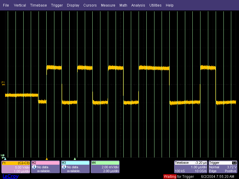
Note the nice sharp edges. In part this is due to the 49Ω resistors rather than 100Ω, but also due to a much shorter cable.
Revision history
- 2016/09/28
- imported from here (bmayton)
- removed separate firmware files; firmware for all platforms is identical. Removed "mac" from folder name inside zip archive. (bmayton)
- Added notes about installing tools on Windows 10; need to look into how this should be done now. (bmayton)
- Added informative section about USB timing; might later move to a separate page (bmayton)
 All content © 2013 Anna Kaziunas
France with editing and additions by Brian Mayton (except where otherwise noted) Some rights reserved.
All content © 2013 Anna Kaziunas
France with editing and additions by Brian Mayton (except where otherwise noted) Some rights reserved.
Licensed under a Creative Commons Attribution-NonCommercial-ShareAlike 3.0 Unported License - Download and Install WinAVR - Has a (broken) installer.