Final project: Light Sensitive Eye
--I can't feel your heartbeat, but I can feel your light.
Based on my prototype in week 0, I finalized my idea and started to design and make. The main purpose of this sensitive eye is to detect the light environment and transform it into both computational data and physical movement. By tracking the light, this eye can react and rotate. In other word, this eye works as a light compass.
Prototype:
|
There are some projects beforehand as good reference.
In Ege's page, he generated a camera which can classify apple and non-apple images. He wrote a random image generator script which can creates patterns similar to the images generated by the board.
Also I found a lot of examples about computer vision and eye mechanism.
A Turing test for computer vision. Human eyes are better at detecting surrounding environment than computers. So vision and eye mechanism are studied in the field of computer vision.
In instructables, there is a project of animatronic eye. 2 mini RC servos are used to control the eye, let it move side to side. Lynxmotion SSC-32 controller is used to generate the code of movement. SSC-32 takes a cmd file to send commands to the servo controller.
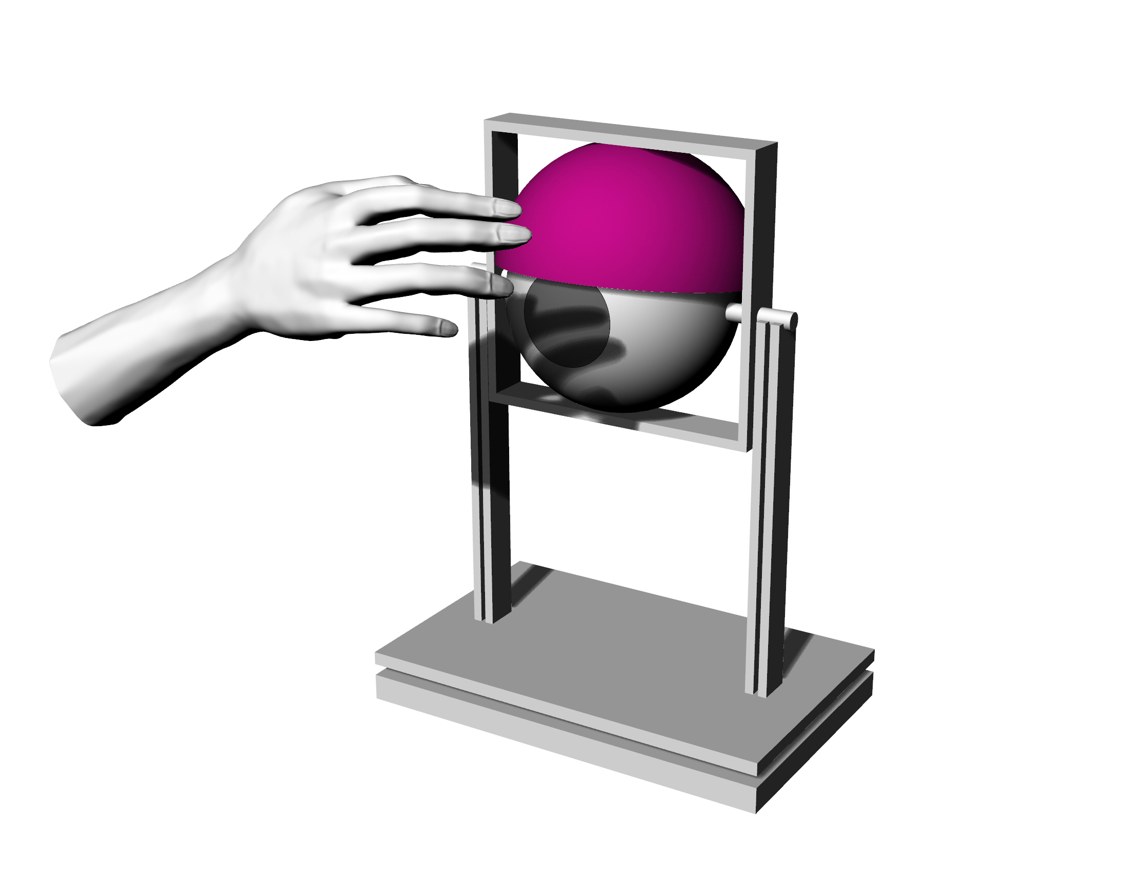
Basic design and mechanism
First I started from eye mechanism design. I modified based on my week 0 prototype. The eyeball has a vertical axis to make it rotate from side to side. Meanwhile the eyelid has a horizontal axis, by which the lid can move up and down.
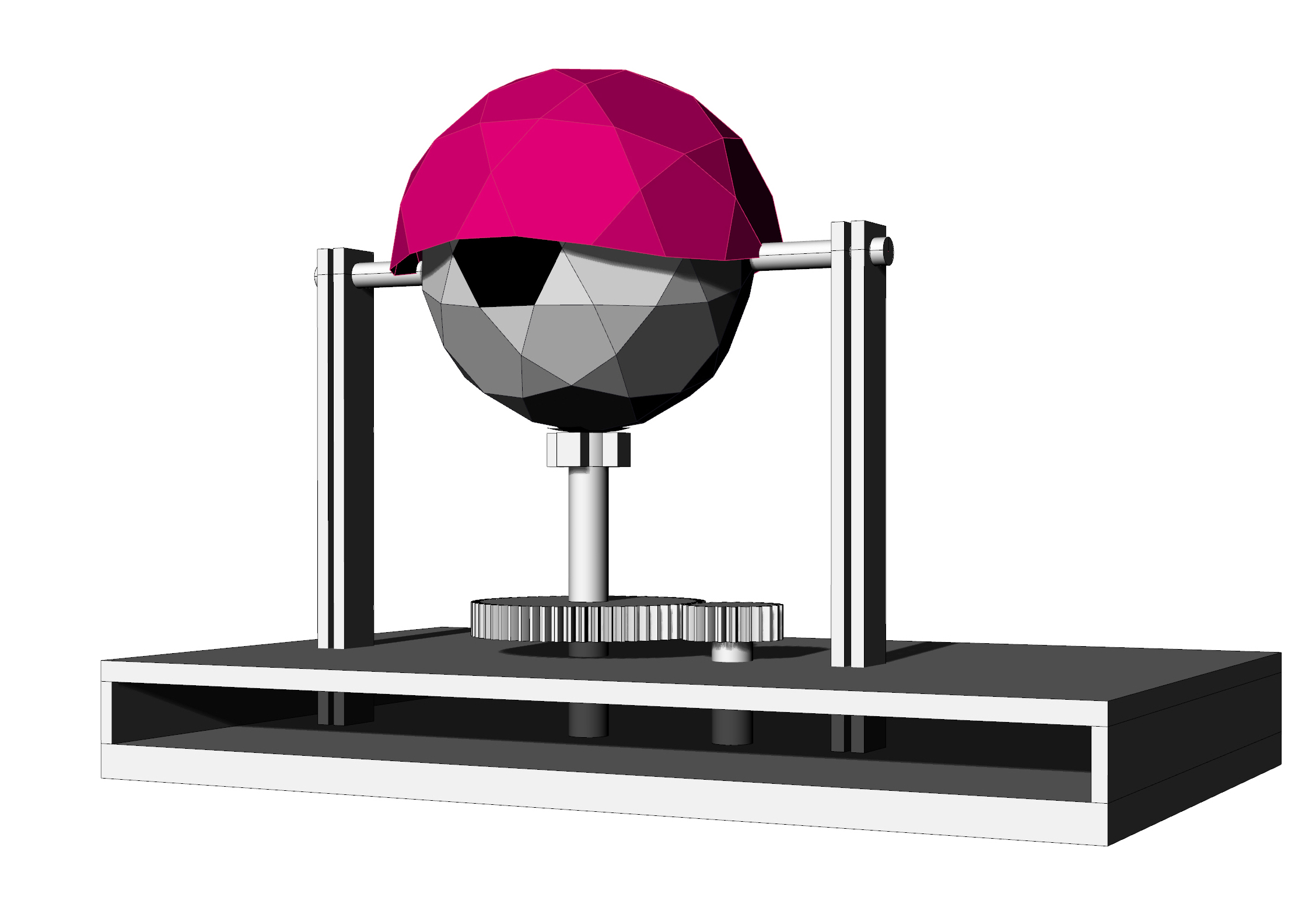
Also, as a designer, I looked at into the form of eyeball and eyelid, made several adjustments, and ended up with a polygon. By far the mechanism is rough because I want to adjust it after designing the electric control system.
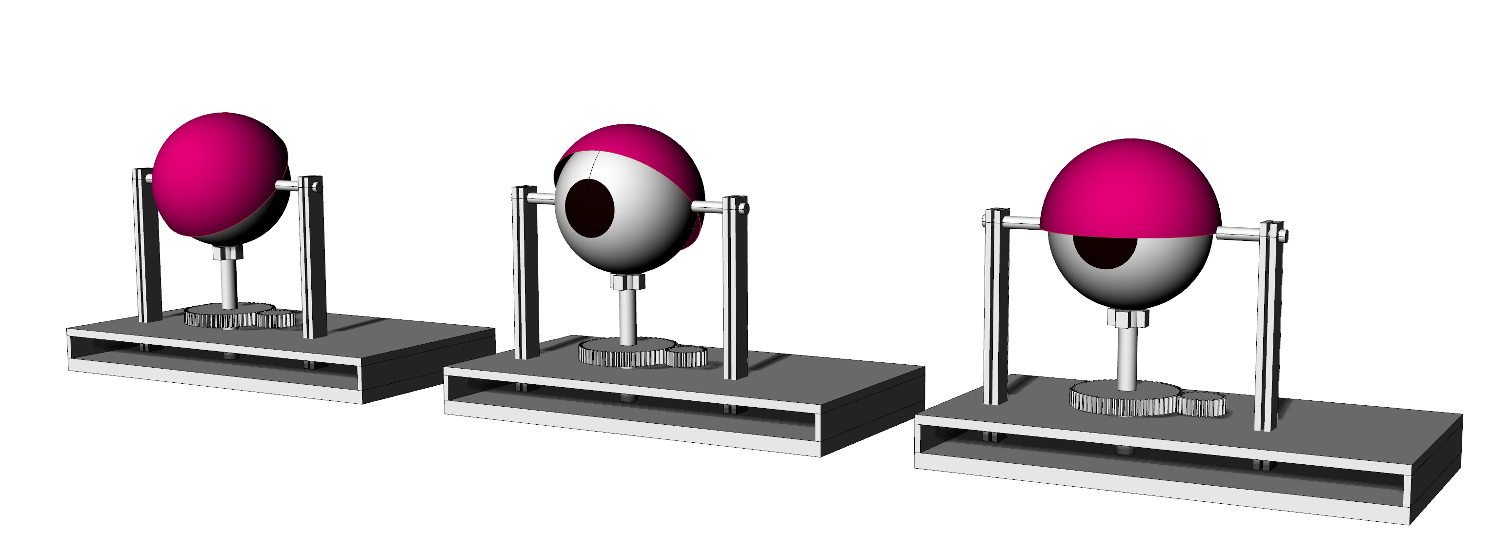
Three eyelid modes:
|
Eyeball generation:
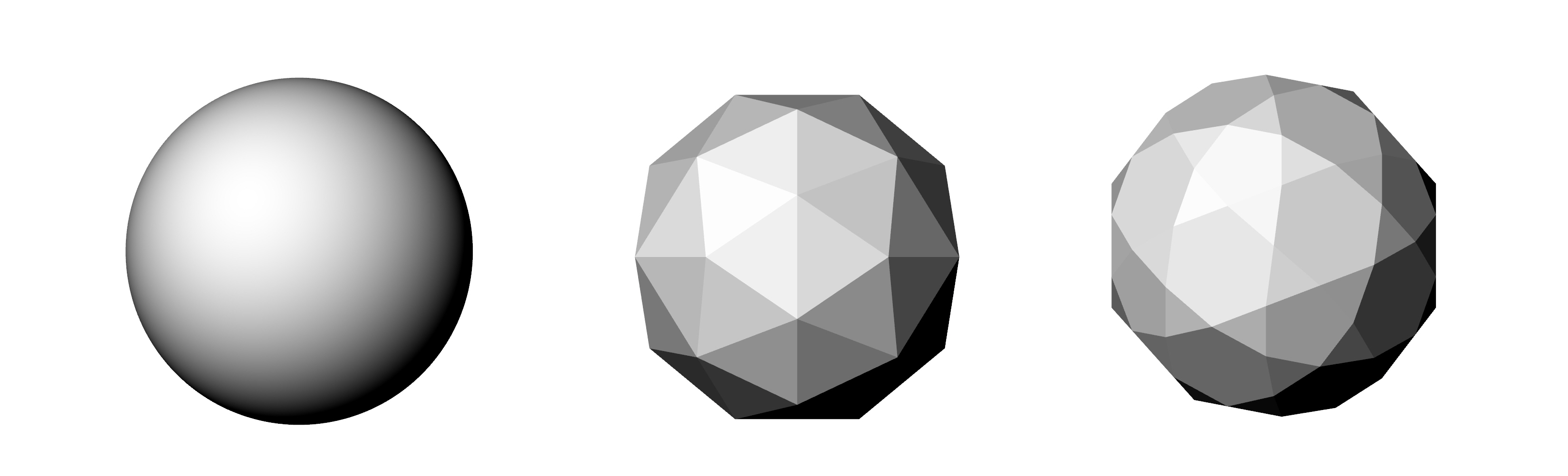
|
|
Electric control system design
Processor: atmega 328. The final board design was based on the board I designed in the input devices week. I used a FTDI cable to give the board power supply from my laptop.
Input sensor: phototransistor.
Output devices: servo motors.
In my input devices week, I switched from attiny44 to atmega328, and added a phototransistor on it. At first I had some problem with the serial communication, in the next couple weeks, I figured it out and fixed that by burn bootloader before programming. Details are in the page of that week.
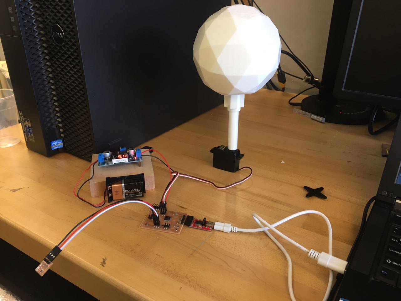
I tested servo motor in output devices week, and figured it out in interface and application week. It is important to connect the negative of external power supply to the GND of the board. My lab mate Yijiang helped me to make the external power supply. The voltage for servos is 4.8- 6V, and meanwhile I had 9V batteries and its cell box. My small 6V batteries don't work well because of bad contact (can't find proper cell box for it), so with Yijiang's help and advices, a small voltage converter and a switch were added to the 9V battery and thus become the final external power supply.
In networking and communications week, I started to build my electric system. I need 4 sensors to control 2 axis. In that week, I managed to adjust my board design, let it be able to connect 4 sensors and 2 motors.
Below is the process of boards design and fabrication. More details are in networking and communications page.
Final scheme:
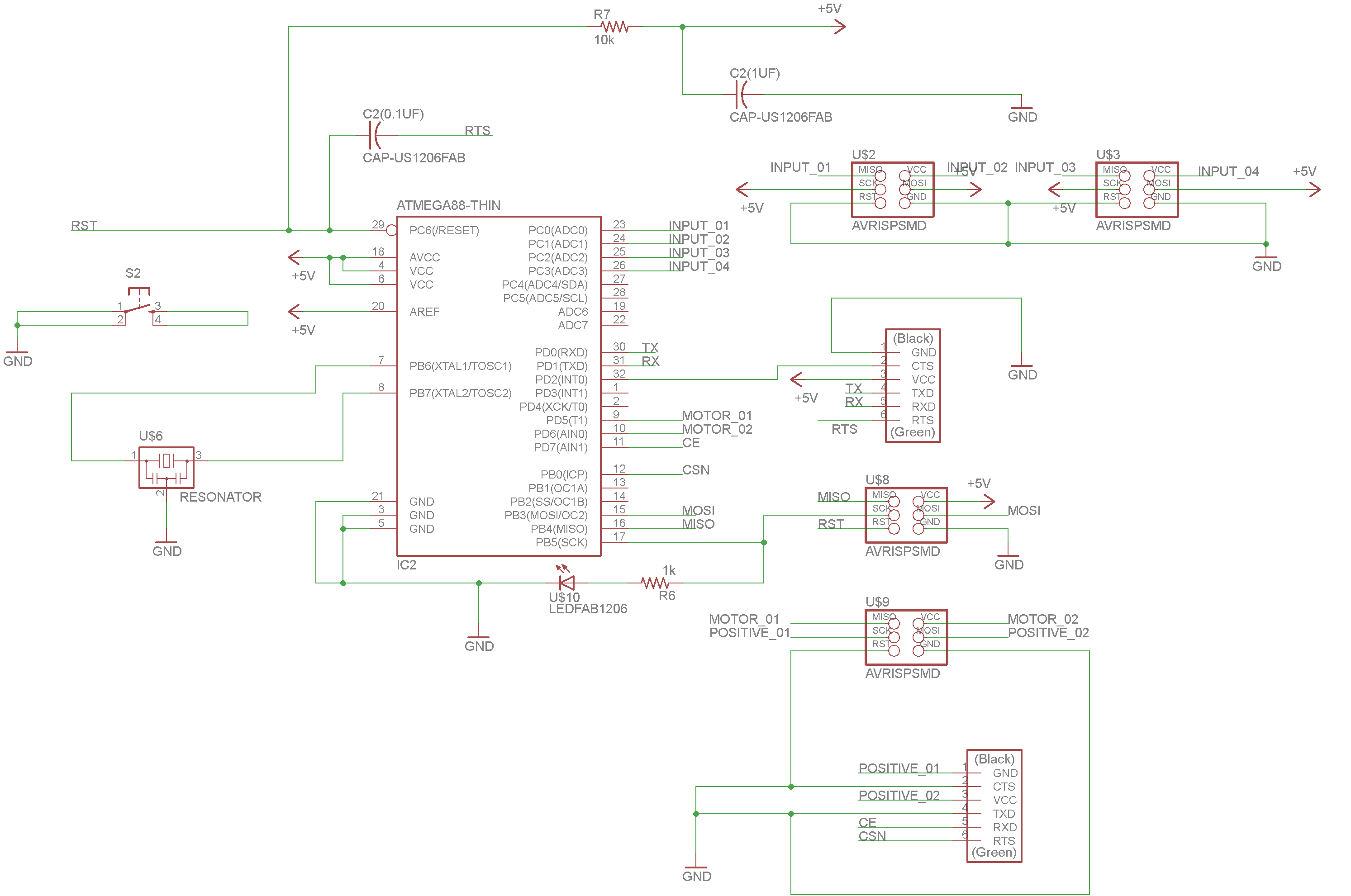 |
Final board:
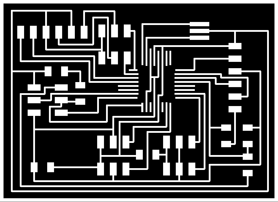 |
Phototransistor scheme and board:
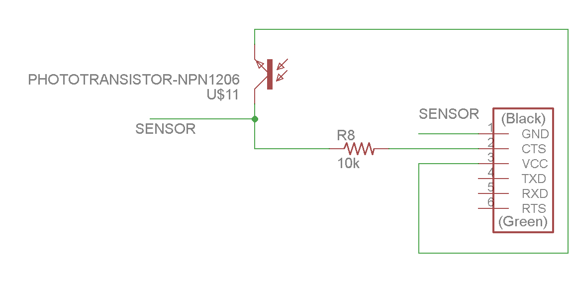 |
 |
Milling and soldering went smoothly. The PCB boards are not perfectly flat, I spent quite a while on adjusting the plane and endmill, testing it on three points instead of one.
PCB milling:
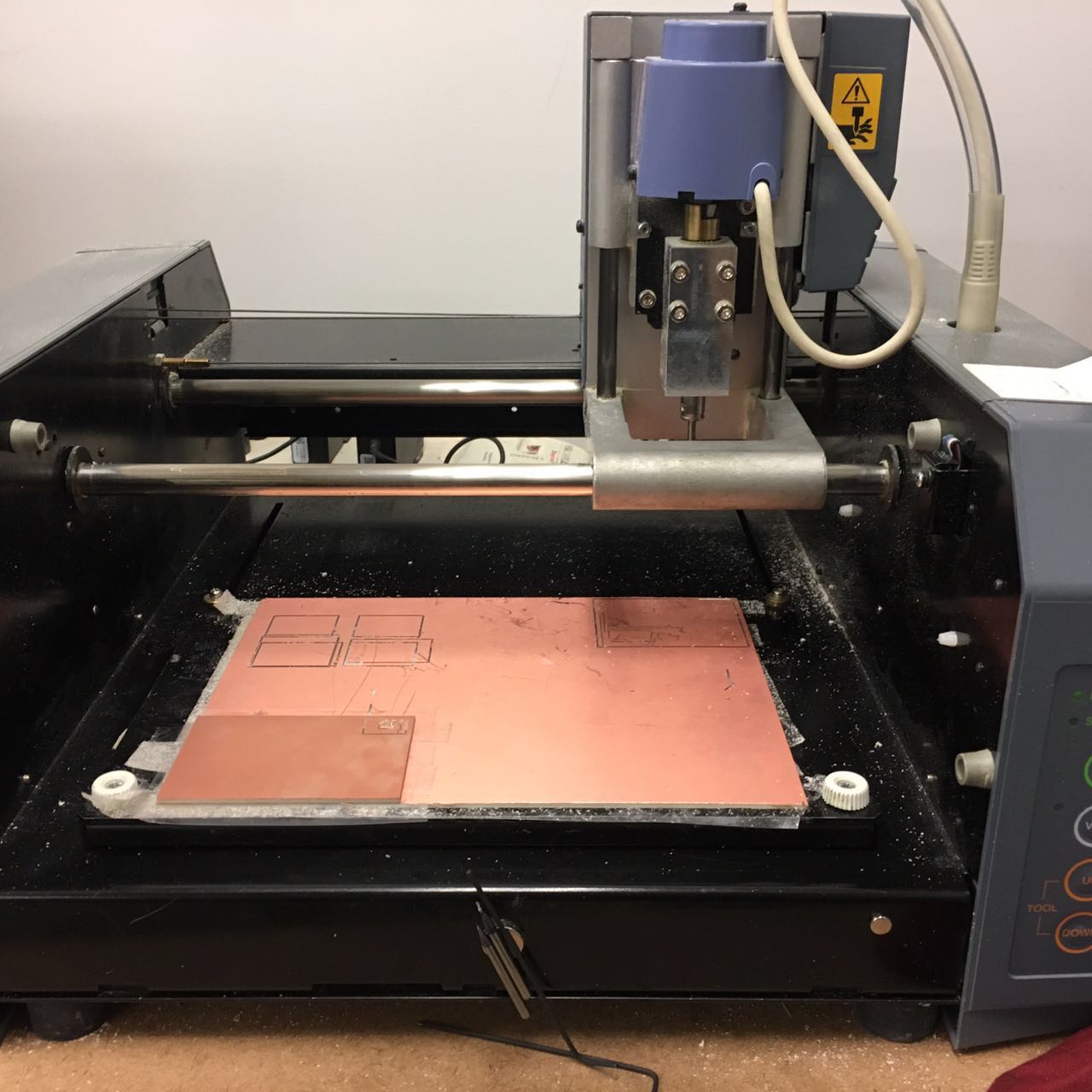 |
Main board:
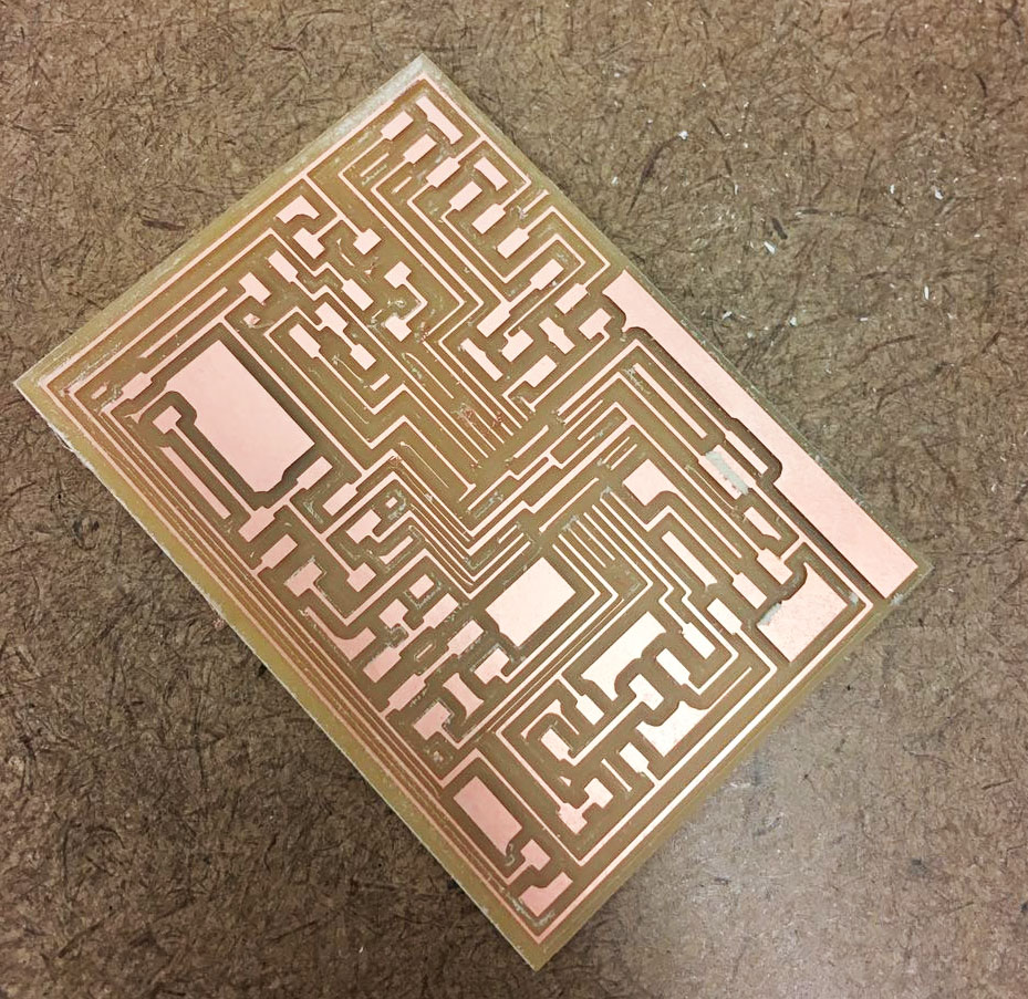 |
Phototransistor board:
 |
Soldering accomplished. Below is the final main board and my 4 sensors.
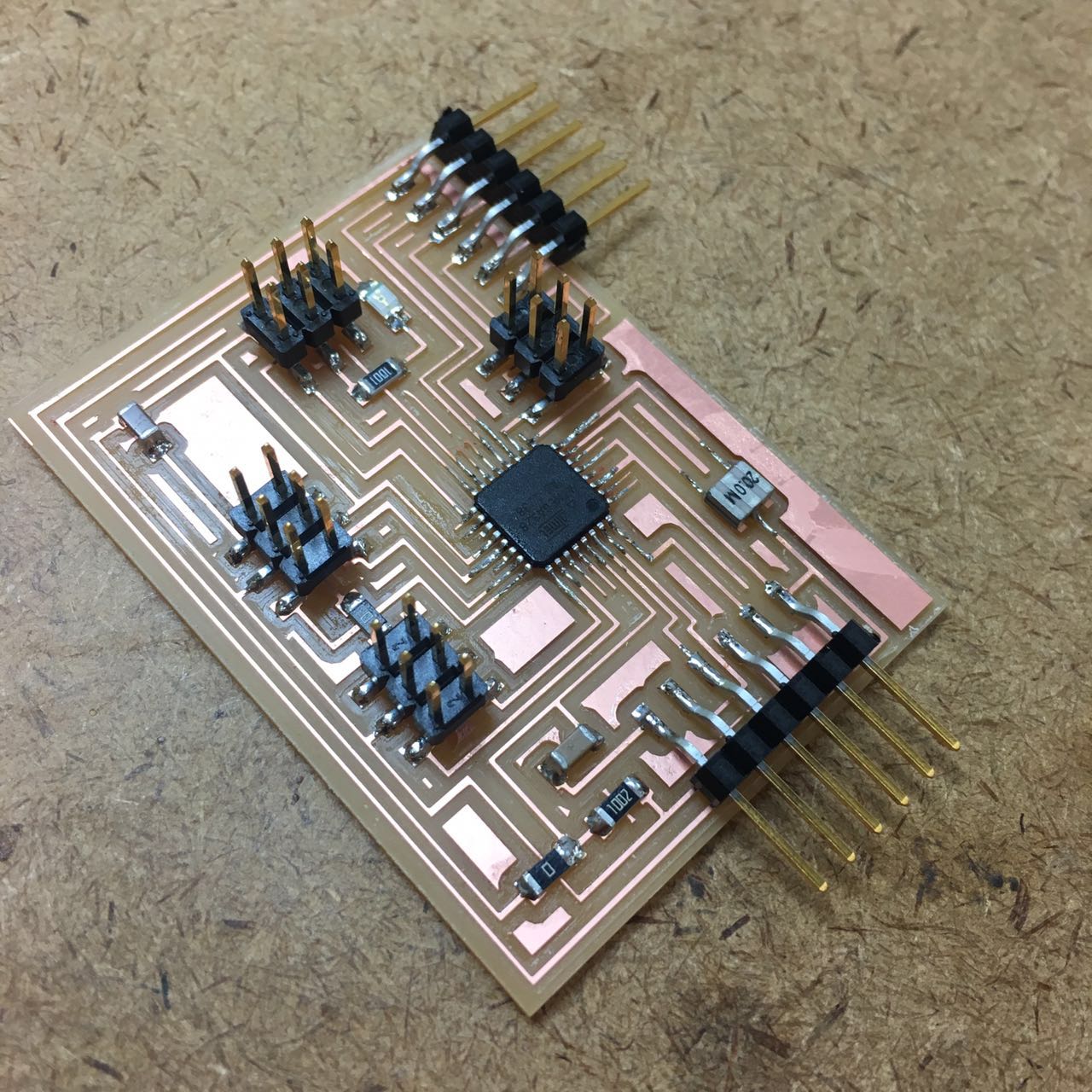 |
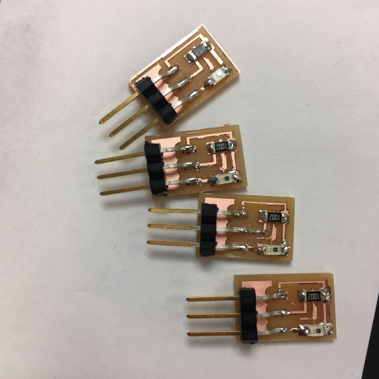 |
Then I started to test in Arduino IDE. I first tested with my 4 phototransistors and 2 servo motors individually, all the ports worked!
Phototransistor wiring up:
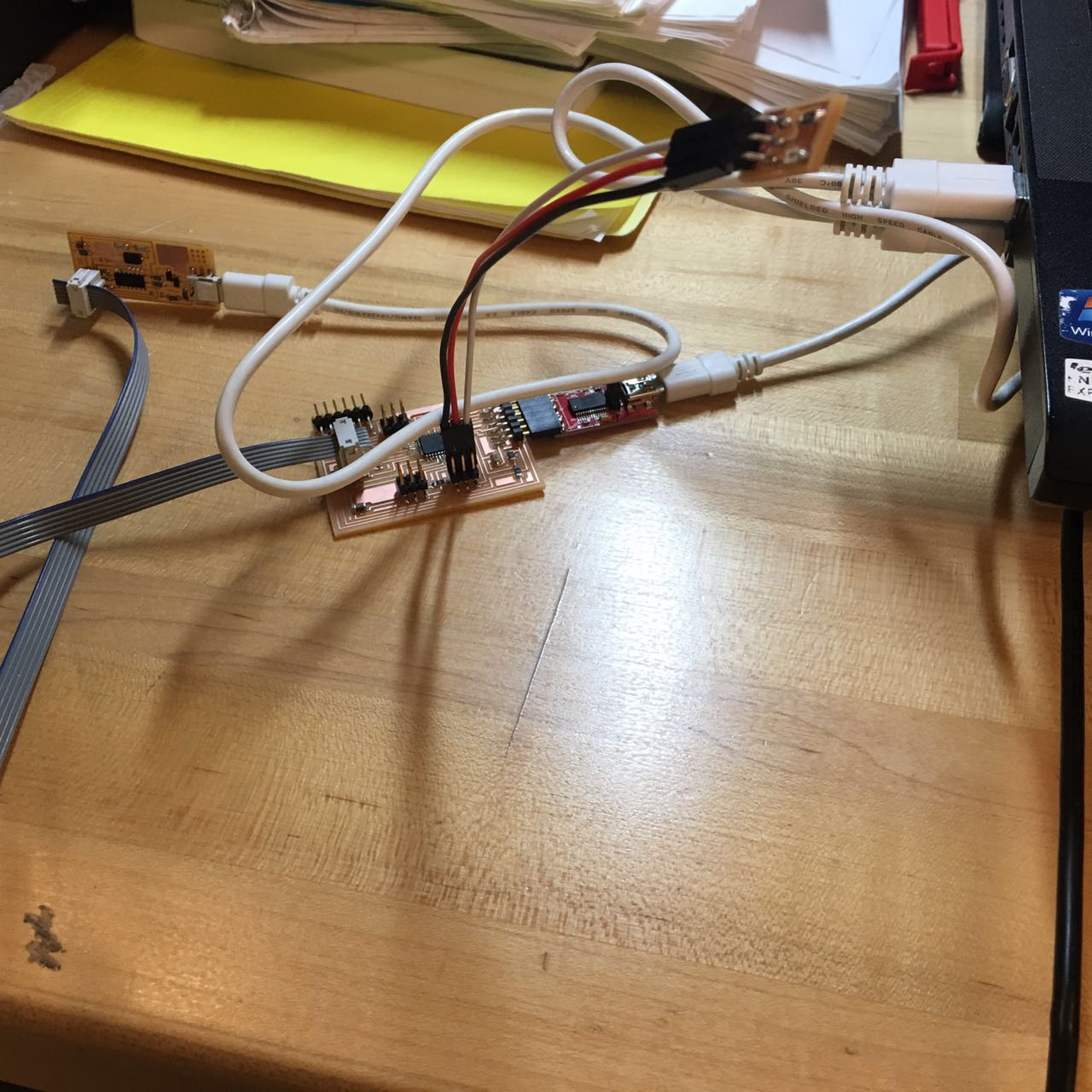 |
Motor wiring up (with the external power supply).
 |
| |
After prepared my board and all the phototransistors/motors, I did a quick test to see if the phototransistor can control the motor.
My code:
#include
//basic set up
Servo servo_ball; //create servo object
int pos_ball = 90;
int photoTran_left = A1;

void setup() {
  pinMode(photoTran_left, INPUT);
  servo_ball.attach(6);

  Serial.begin(9600);
}

void loop() {
  int reading_left = analogRead(photoTran_left);
  if (reading_left < 100){
    pos_ball = 0;
    servo_ball.write(pos_ball);
  }
  if (reading_left > 500){
    pos_ball = 90;
    servo_ball.write(pos_ball);
  } }
I made a mistake connecting the phototransistor at this time. Collector should be connected to VCC and an analog pin, while Emitter should be connected to GND. I connected Collector to GND while Emitter to VCC, and this led to the serial keeping reading 0. Luckily I found this bug. It worked when I run my code again! The servo reacted as the light condition near the phototransistor changed.
| |
Further design and wires system
After basic test of my electronics system, I went back to the model, further designed and adjusted the physical shape and all the mechanics details. The red parts are the positions of motors and sensors.
 |
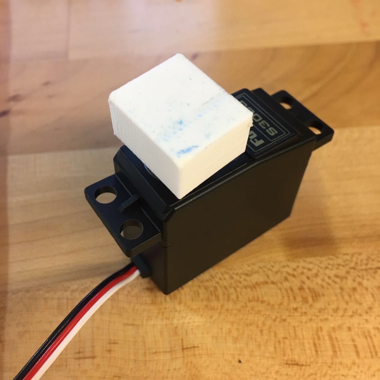
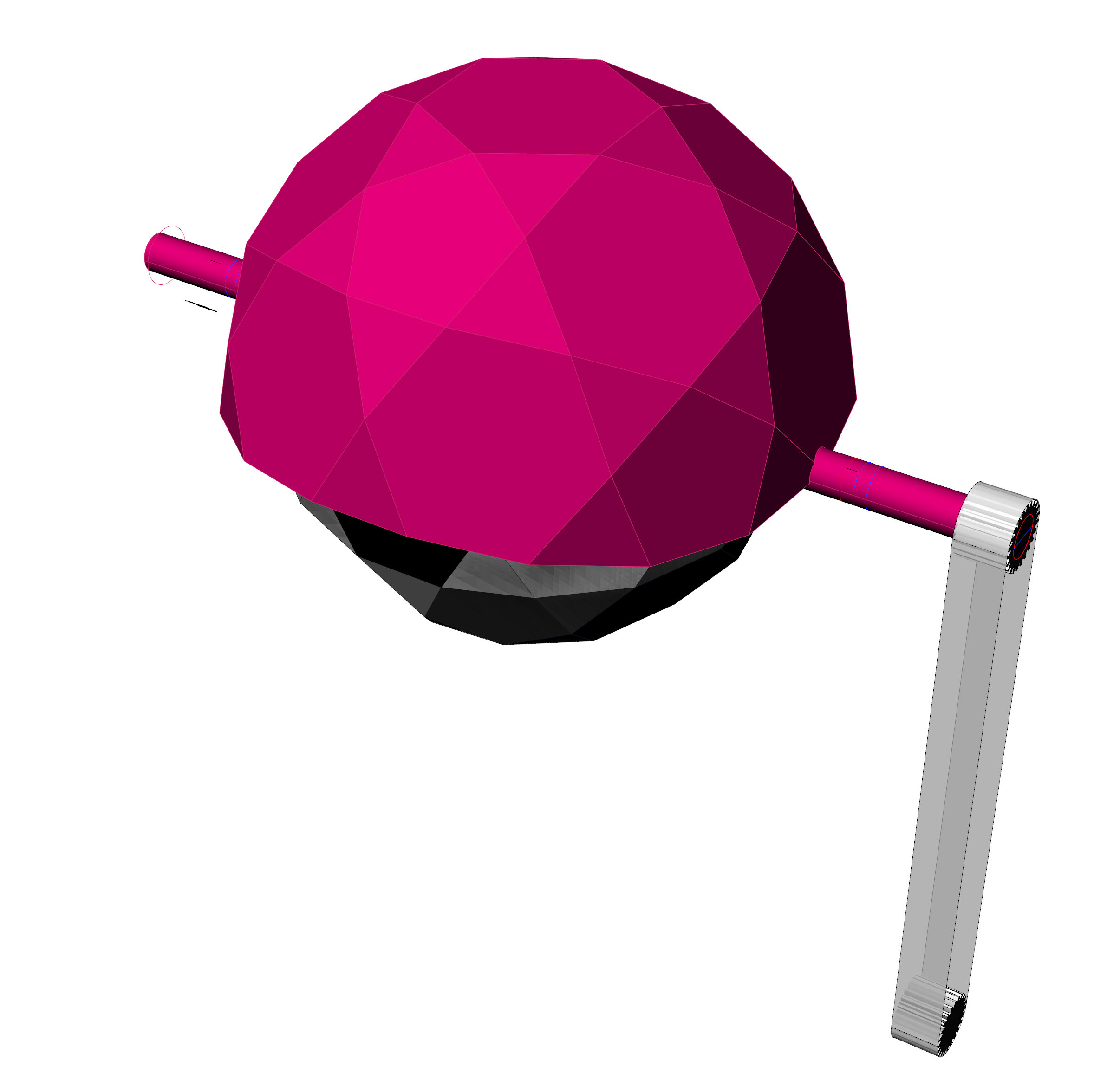
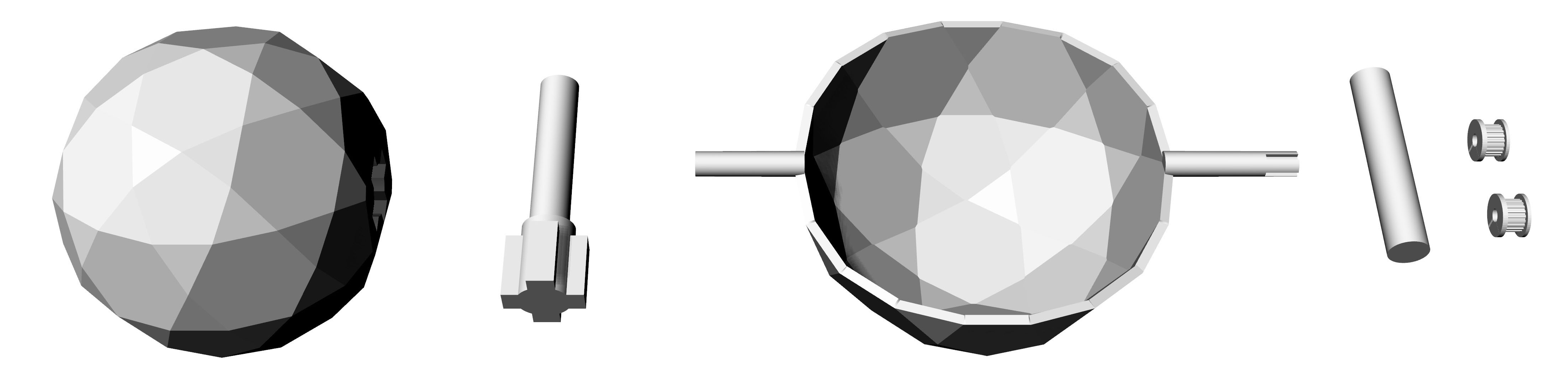
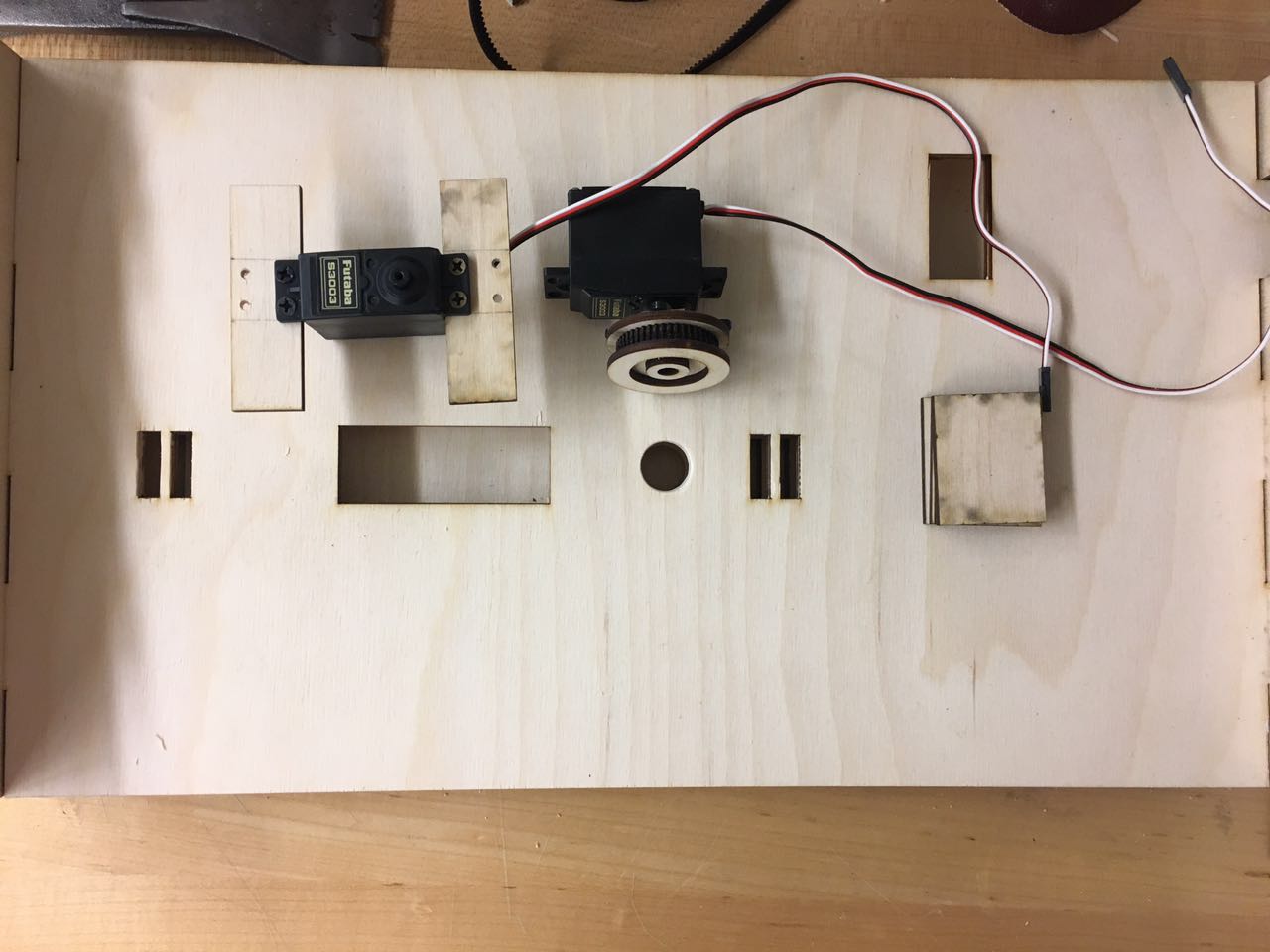
For the eyeball, I designed a cross shaped connecter. Also, since I needed to connect the axis to the motor, I did several tests. The precise model of my motor Futaba S3003 can be downloaded from grab cad.
On the head of this motor there is a small gear with teeth. I decided to connect the axis on the top of this gear, so I made a Boolean difference, first printed a small box to see if they can be connected. At first, I chose "normal quality" in 3D printing, and the teeth inside the box could not be printed successfully. It turned out to be the issue of resolution. Then I chose "high quality" with the resolution of 0.1mm, and this time the print can be connected to the motor tightly and stably! I also designed two gears to stable the eyeball and prevent shaking when rotating.
 |
Precise servo model from grabcad:
 |
Connecting test:
 |
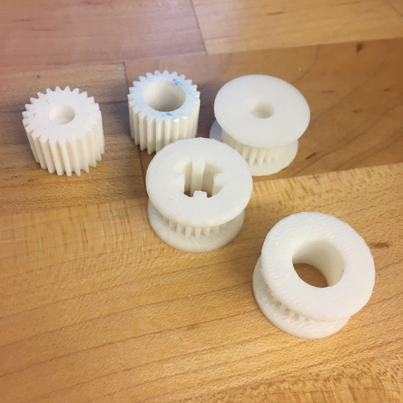
Eyelid needs a motor to drive the horizontal axis. At first I considered to connect a motor directly to the horizontal axis, but soon I found thus I can not arrange most of the wires inside the base box. So I reconsidered the design of this part, and tried to use a belt as a force conveyor. I designed two pulleys which can be 3D printed.
 |
All the tests of the pulley. Finally I decided to use the larger one because they are more stable.
 |
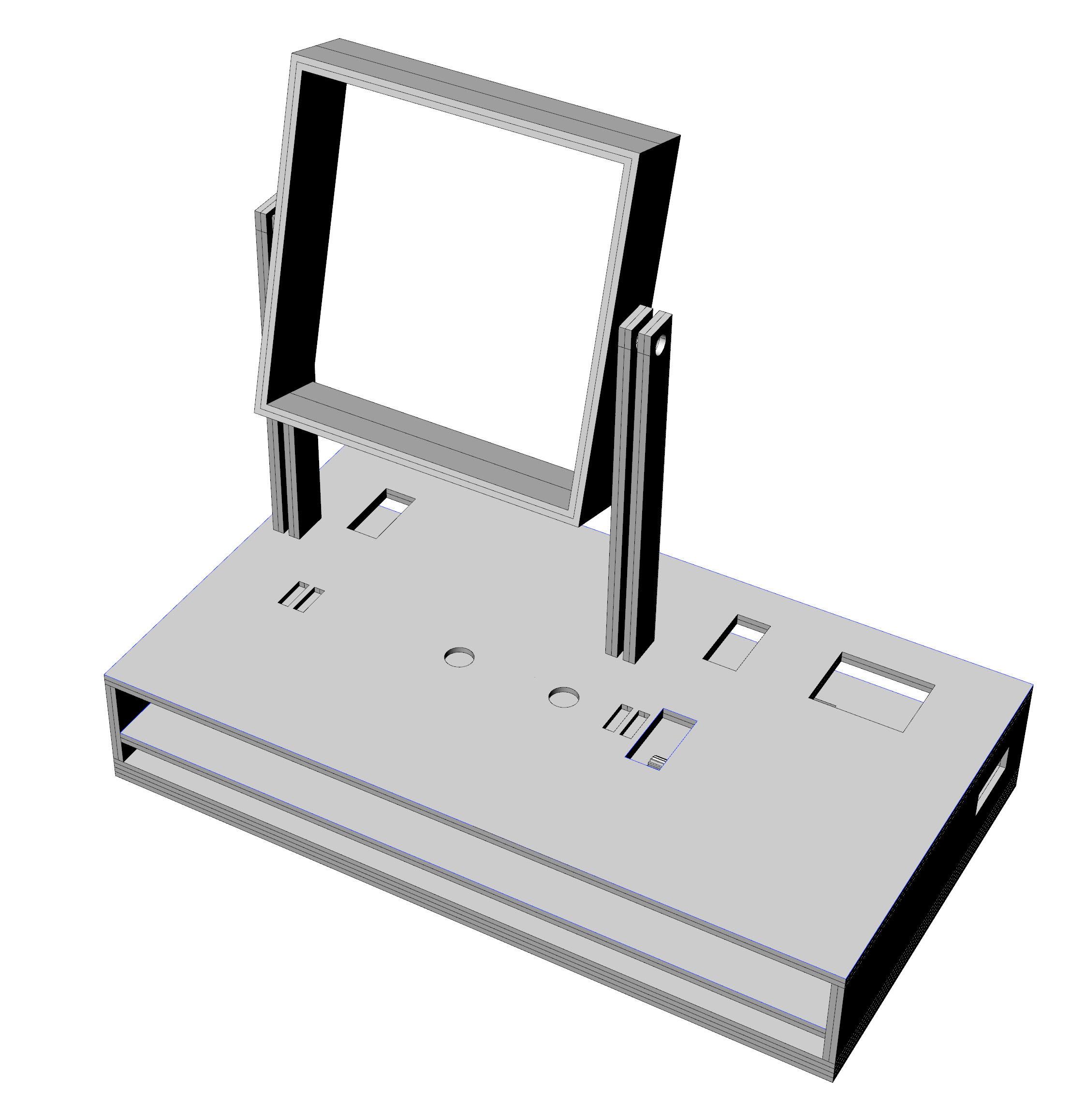
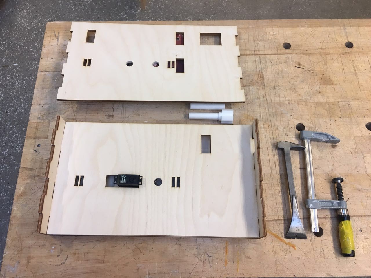
Wires are arranged in an open box below the eye. I want this box open because it may be more convenient for me to test and adjust. This box contains two layers in order to fix two motors in different height. On the top layer, I designed two openings to let the wires of phototransistors go through. Also I designed an opening on the right side of the box, in order to let the power supply USB for my board go through. The whole base box is pressed-in structure, which is what I learned in the laser cut week.
Sensor frame: I designed a square frame to hold the sensors. The frame is also pressed in, which can make the assembling easier. Frame is connected to the vertical column.
Base and frame:
 |
Components fabrication
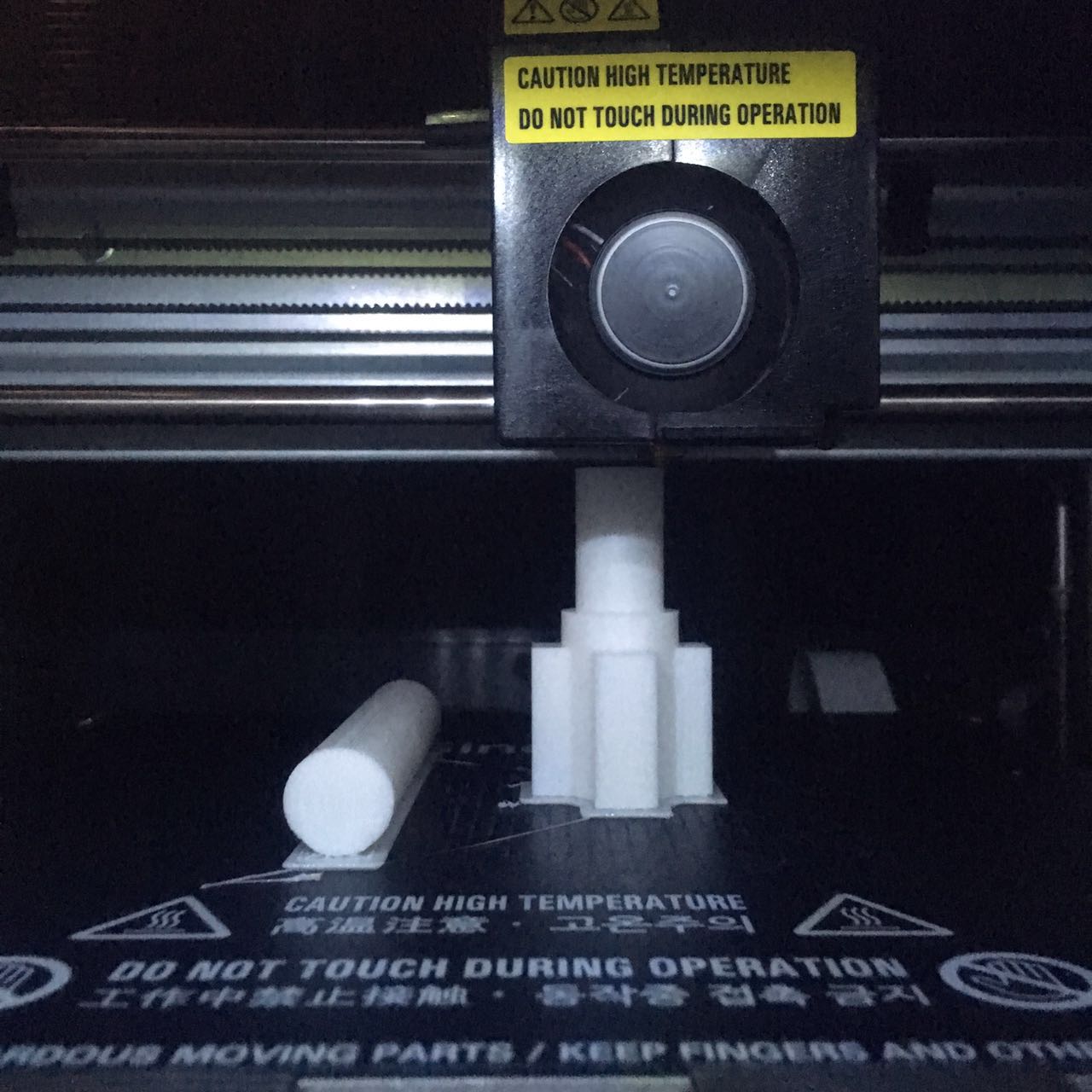
After carefully considered the details of my design, I started to fabricate all the components. The methods I used in fabrication are 3D printing, laser cut, and a little bit sewing (in assembling). For 3D printing, I had 6 major components, including eyeball, eyelid, two vertical axis and two pulleys. My first 3D print of the eyelid failed. Instead of 3dwox in architecture shop, I first tried makerbot in my lab. This machine is faster, and the setup is similar to 3D WOX. I set up the file and run the printer, but soon found due to the imperfect plane, the filament could not be adhere to the model. I rebuilt the plane, adjust the distance between it and the printing head by using a piece of paper, but I still failed several times. Then I went back to 3D WOX in shop, since this printer has a heated plane and more precise control, I succeeded to print the eyelid finally. 3D printing of other components went smoothly. Since 3D printing is slow, this step took a lot of time.
 |
Axis during printing:
 |
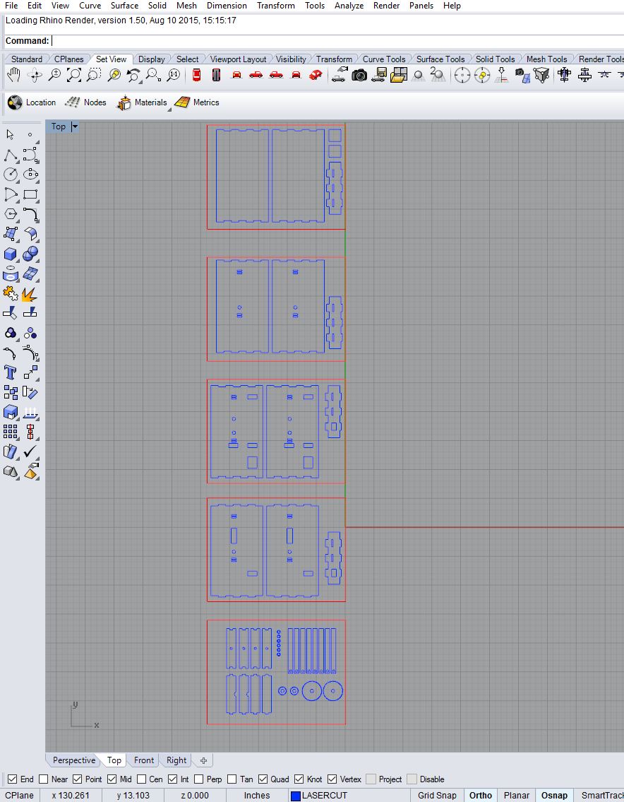
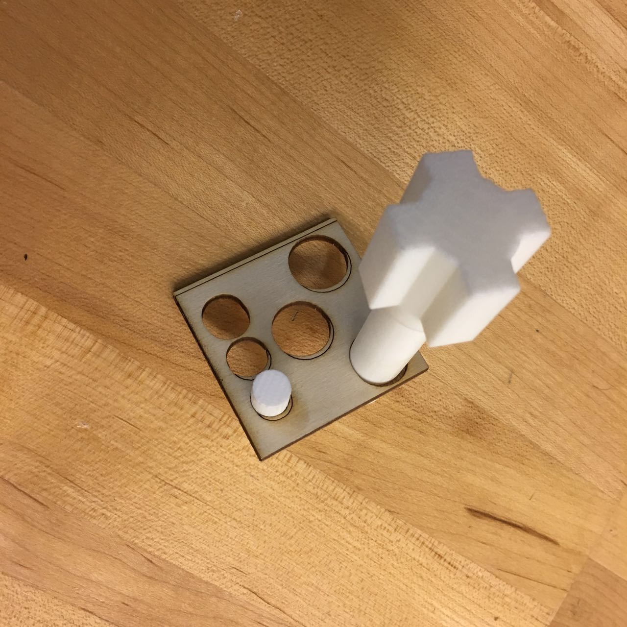
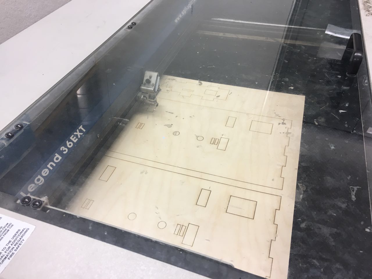
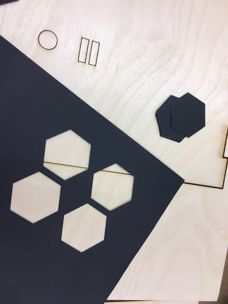
For laser cut, I had all the frame and some of the gears. I bought 6 pieces of poly wood from art and craftsman. They took me nearly $40. This is my first time to cut 1/8 inch wood using the laser cutter in shop, I asked Calvin for advices of the parameter and did a couple of tests by myself. Finally I decided to do 20% speed and 95% power. I also did tests to see if I need to enlarge the hole of the axis. After testing several different diameters, I maintained the original size. Laser cutting went much more quickly than 3D printing. I also got one piece of paper board and used laser cutter to get a hexagon as the pupil.
 |
Test cutting:
 |
Frame during laser cutting:
 |
Paper cutting:
 |
Before I started the whole assembling, I assembled the eyeball part to see if the servo can handle it. It worked! Also by this time I am a little worried about if the belt and the pulley can drive the horizontal axis. Maybe by adding 2 gears I can make the belt more stable. So I change my design and added some supporting gears as a try. I re-cut the frame.
 |
Assembling and mechanics adjusting
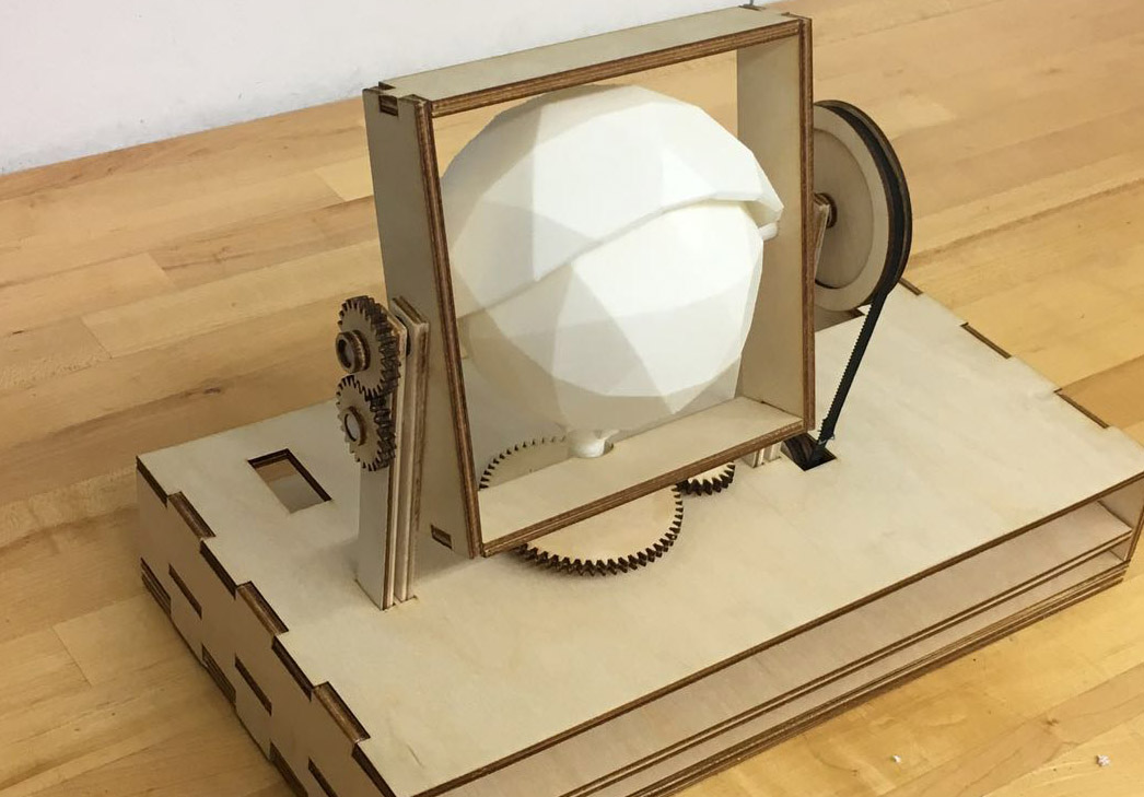
Finally I got all my components here!
When Assembling, I sanded some holes to make them smoother, as well as some connectors. When I worked in wood shop, Jen told me actually laser cutter is not accurate. When doing tests on laser cut, do the entire connectors instead of only one. That is because the angles and fractions are very crucial in assembling. My assembling included several steps:
- Base box assembling. I used hammer to deal with some huge fraction.
- Assembling aye ball and eye lid to the frame.
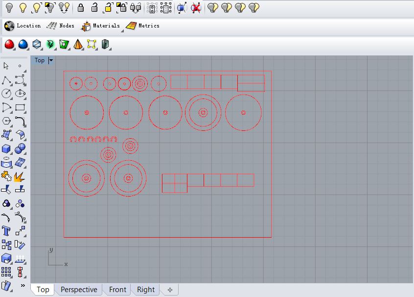
- Gears and pulleys. This step is the hardest one. I found to assemble the pulley and the horizontal axis is very hard because 3D printing cause imperfections in those precision parts. I tried to melt come corners to make it easier to assemble, but failed several times. Finally I gave up and tried other ways: I tried wood to make those pulleys. Also I enlarged the diameter of the wood pulley in order to gain a better traction. I calculated the single tooth of the pulley, applied them to two bigger circles, did a rough calculation of the distance and angle. Here is a useful gear generator on line. After I changed the material of pulley from filament to wood, assembling becomes much more easier because wood is easier to sand and adjust. Finally I made it! At the same time, I also cut some squares as the fixation for my motors.
- Motor fixing. I need the two motors to be fixed when the whole installation is working. At first I used glue, but soon found out glue doesn't work well between plastic motor and wood as I expected before. Then my lab mate Yijiang help me to use rivets to fix them. I also used hot melt adhesive as an insurance.
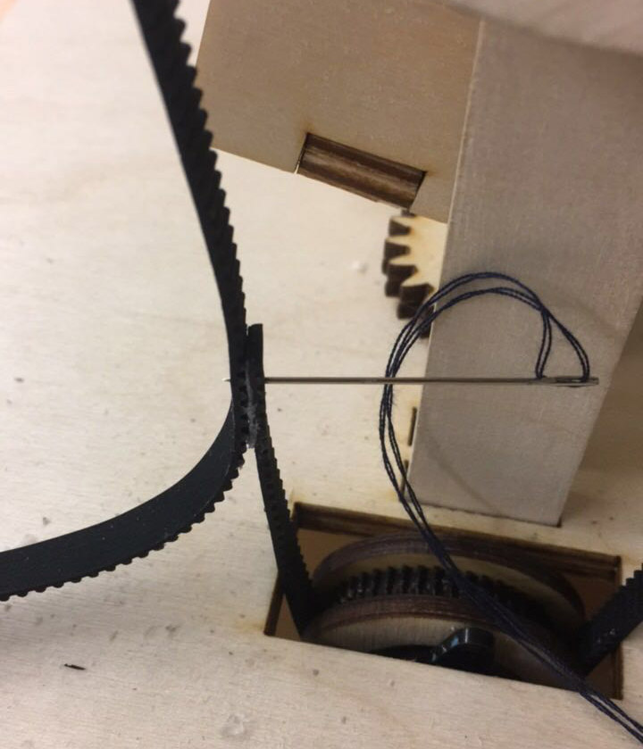
- Belt sewing. As the final part of assembling, I sewed the belt together. It is not easy as I thought to sew by hand. Finally with the assistance of pliers and some glue, the belt sewing was done!
 |
 |
The connecter on the edge of the horizontal axis is very hard to be assembled with the pulley. I realized it would be much better to design triangles instead of right angles.
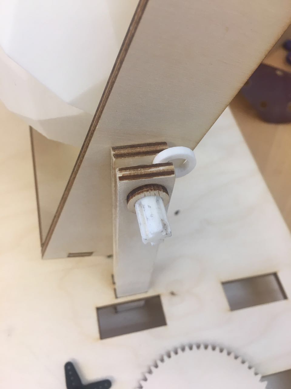 |
Another plan to make pulleys:
 |
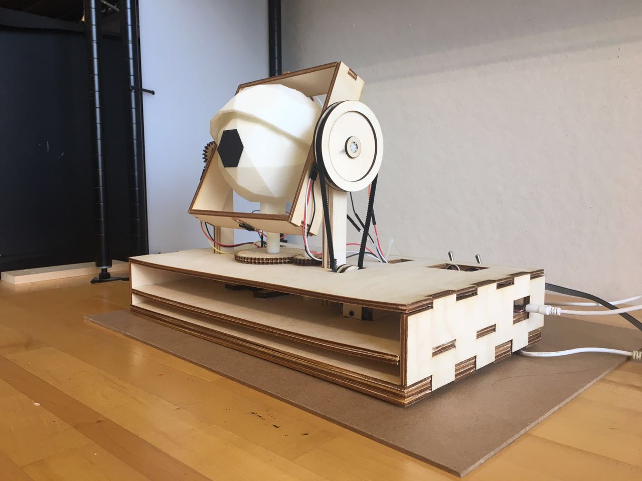
The wood pulley fit the belt well.
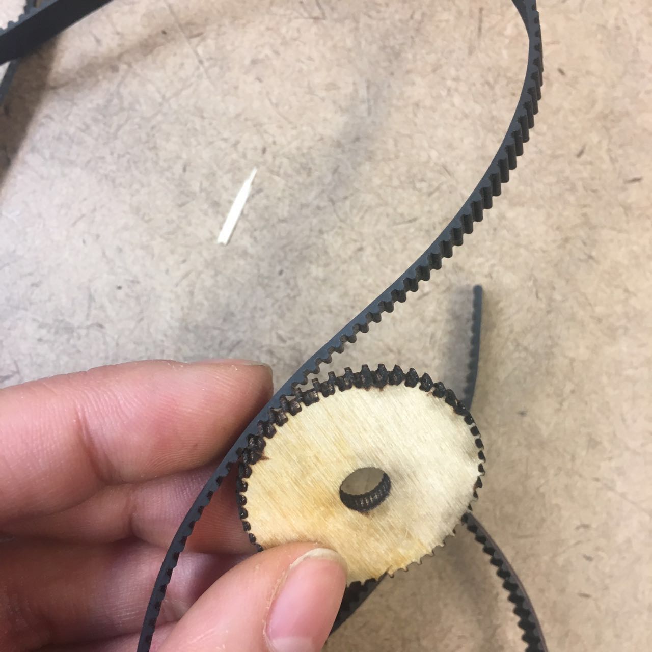 |
The cross-shaped holes are going to be connected to the horizontal axis.
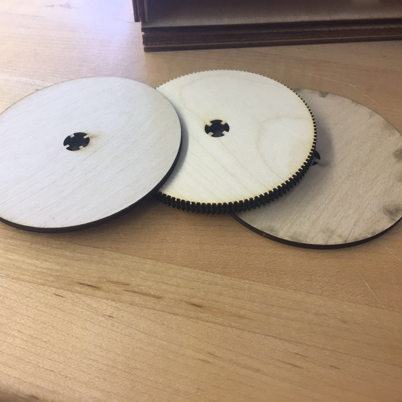 |
 |
 |
Now it is ready for electronics!
 |
Wiring up and Testing
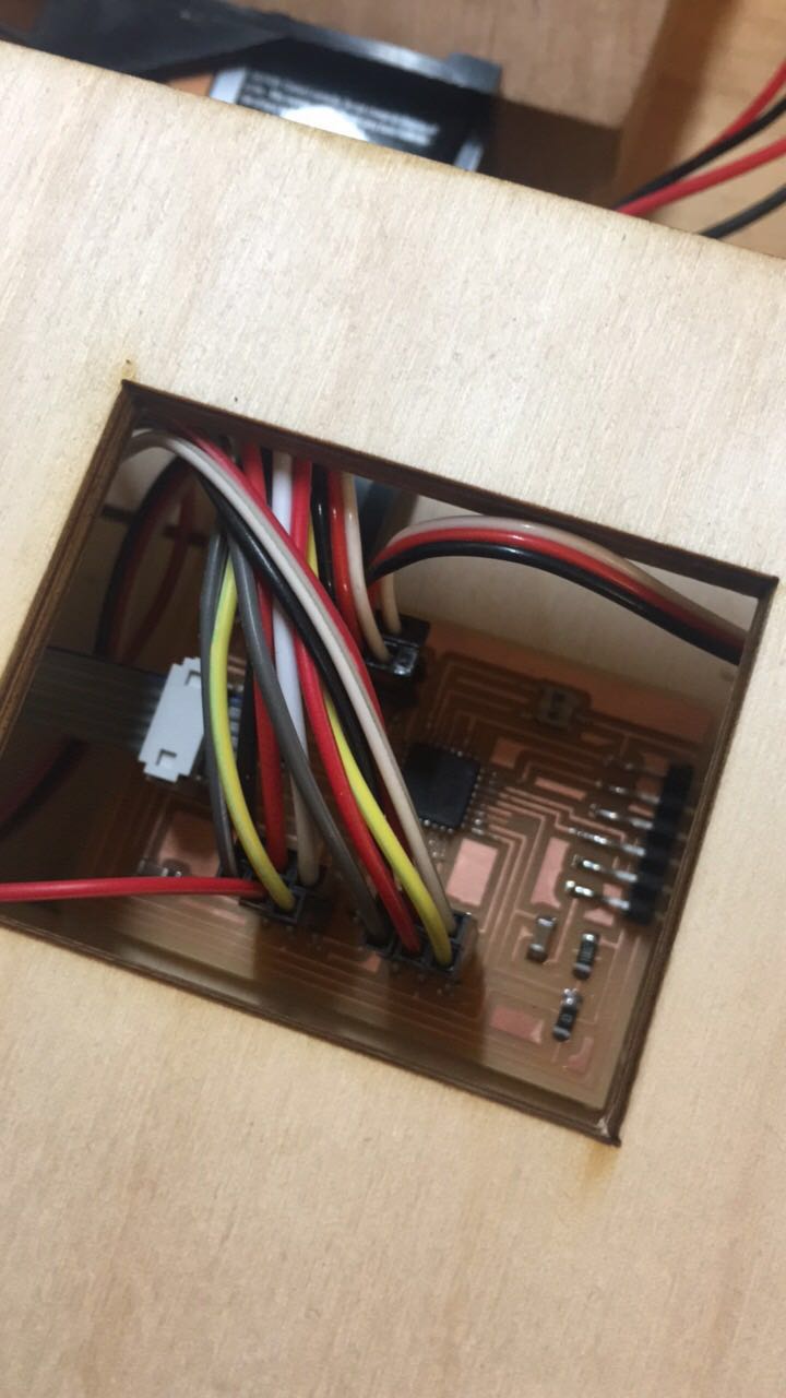
After assembling all the mechanics, I moved to electronics. The first step is wiring up. Following my scheme, wiring up went smoothly. I noted all the pins down when connecting. In order to make all the wires clean and easy to recognize, I used white or yellow wire as signal wire which is connected to the pin, red wire as VCC, black wire as GND.
 |
I hide all my complicated wires system here:
 |
 |
After wiring up, I used my programmer, usbtiny, to program the board. At first, I did a simple test of each phototransistor and each motor. After ensuring that all the components are working, I first tested the vertical axis.
Below is the first version of code:
  void loop() {
  int reading_right = analogRead(photoTran_right);
  int reading_left = analogRead(photoTran_left);
  if (reading_left < 100){
    pos_ball = 45;
    servo_ball.write(pos_ball);
    }
  if (reading_left > 500){
    pos_ball = 90;
    servo_ball.write(pos_ball);
  }
  if (reading_right < 100){
    pos_ball = 135;
    servo_ball.write(pos_ball);
    }
  if (reading_right > 500){
    pos_ball = 90;
    servo_ball.write(pos_ball);
  }
  }
After I run it, I realized there is a collision in my code. If there is no light on left phototransistor while light on the right one, the motor receives two instructions: stays at 90 and goes to 135. Then the two instructions counteracted. So I modified the code as:
  if (reading_right > 400 & reading_left > 400){
  pos_ball = 90;
  servo_ball.write(pos_ball);
  }
And also I modified the number of phototransistors' reading, and tried to find the most sensitive range.
After testing vertical axis, I tested the horizontal axis. I increase the degree it rotating gradually, and ended up with 25.
My final code:
#include
//set up
Servo servo_lid; //create servo object
Servo servo_ball; //create servo object
int pos_lid = 45;
int pos_ball = 90;
int photoTran_up = A2;
int photoTran_down = A3;
int photoTran_right = A0;
int photoTran_left = A1;

void setup() {
  pinMode(photoTran_up, INPUT);
  pinMode(photoTran_down, INPUT);
  pinMode(photoTran_right, INPUT);
  pinMode(photoTran_left, INPUT);
  servo_lid.attach(5);
  servo_ball.attach(6);


// debug
  Serial.begin(9600);
}

void loop() {
  int reading_up = analogRead(photoTran_up);
  int reading_down = analogRead(photoTran_down);
  int reading_right = analogRead(photoTran_right);
  int reading_left = analogRead(photoTran_left);


//left light sensoring
  if (reading_left < 100){
    pos_ball = 45;
    servo_ball.write(pos_ball);
//    for (pos_ball = 45; pos_ball <= 80; pos_ball += 1){
//      servo_ball.write(pos_ball);
//      delay(1000);
    }

//  if (reading_left > 400 & ){
//    pos_ball = 90;
//   servo_ball.write(pos_ball);
 //   for (pos_ball = 80; pos_ball >= 45; pos_ball -= 1){
 //    servo_ball.write(pos_ball);
 //     delay(1000);
//    }


// right light sensoring
   if (reading_right < 200){
    pos_ball = 135;
    servo_ball.write(pos_ball);
   }

// eye ball go back to original position
   if (reading_right > 400 & reading_left > 400){
    pos_ball = 90;
    servo_ball.write(pos_ball);
   }

// up light sensoring
  if (reading_up < 100){
    pos_lid = 90;
    servo_lid.write(pos_lid);
  }

//down light sensoring
  if (reading_down < 100){
    pos_lid = 0;
    servo_lid.write(pos_lid);
  }

//eyelid go back to original position
  if (reading_up > 400 & reading_down > 400){
    pos_lid = 45;
    servo_lid.write(pos_lid);
  }

 }
//  if (reading_2 < 100){
//    pos_1 = 0;
//    servo_1.write(pos_1);
//  }
//  if (reading_3 < 100){
//    pos_2 = 45;
//    servo_2.write(pos_2);
//  }
//  if (reading_4 < 100){
//    pos_2 = 0;
//    servo_2.write(pos_2);
//  }
//  int reading = analogRead(photoTran);
//  Serial.println(reading);
//  delay(50);
//  pos = 1;
//  myservo.write(pos);
//  delay(2000);
And finally the light sensitive eye worked! I can even use multiple light resources to effect it. Below is the video:
| |
It's my first time combine electronics, design, fabrication and mechanics all by myself! And my own research is about computer graphics and vision, I am always interested in human eyes and believe this electric eye can be a start point. I can assemble multiple functions to it in the future, such as image recognition, motion detection, etc. I learned a lot from this class, the most important thing is the ability to debug and trouble shoot. Especially for electronics part, I have zero experience about that, so at the very beginning I relied on TAs when I met trouble. Gradually I understood the workflow from scratch to program, and I managed to handle a completed board design and debug by myself.
Material list and links:
3D printing filaments.
Poly wood board(art and craftman).
3.3V/5.5VFTDI: $7.99.
9V Battery&convertor&switch: $7.95.
Futaba S3003 servo motor
:$11.03.
Servo belt
: $ 8.89.
Phototransistor.
Cooper board.
Atmega 328.
6pin header.
0 ohm resistor.
1K ohm resistor.
10K ohm resistor.
LED.
1 uF capacitor.
0.1 uF capacitor.
20 MHz resonator.
All the design files (including previous weeks) are available by contacting me directly.
My tutorial of image compressing.