Assignment 12: Networking and Communications
For my final project I need the communication between phototransistor and servo motor. I can put the port of them on one board, and also I can design two boards to control phototransistor and motor separately by using network, like a remote control. It is beyond my final project proposal, but I want to try this week. I am interested in wireless communication, I decided to try NRF24L01+ with an Arduino library.
According to Wikipedia, Radio frequency (RF) is any of the electromagnetic wave frequencies. RF usually refers to electrical rather than mechanical oscillations. Although "RF" is used as a synonym for radio, to describe the use of wireless communication, as opposed to communication via electric wires.
For NRF24L01+, it is a highly integrated, ultra low power FG transceiver. Dan Chen's page is a very useful tutorial this week.
Dan Chen's page: Networking & Communications.
Another tutorial to set up NRF24L01+ in arduino: get started with NRF24L01+ on arduino.
Board design and making
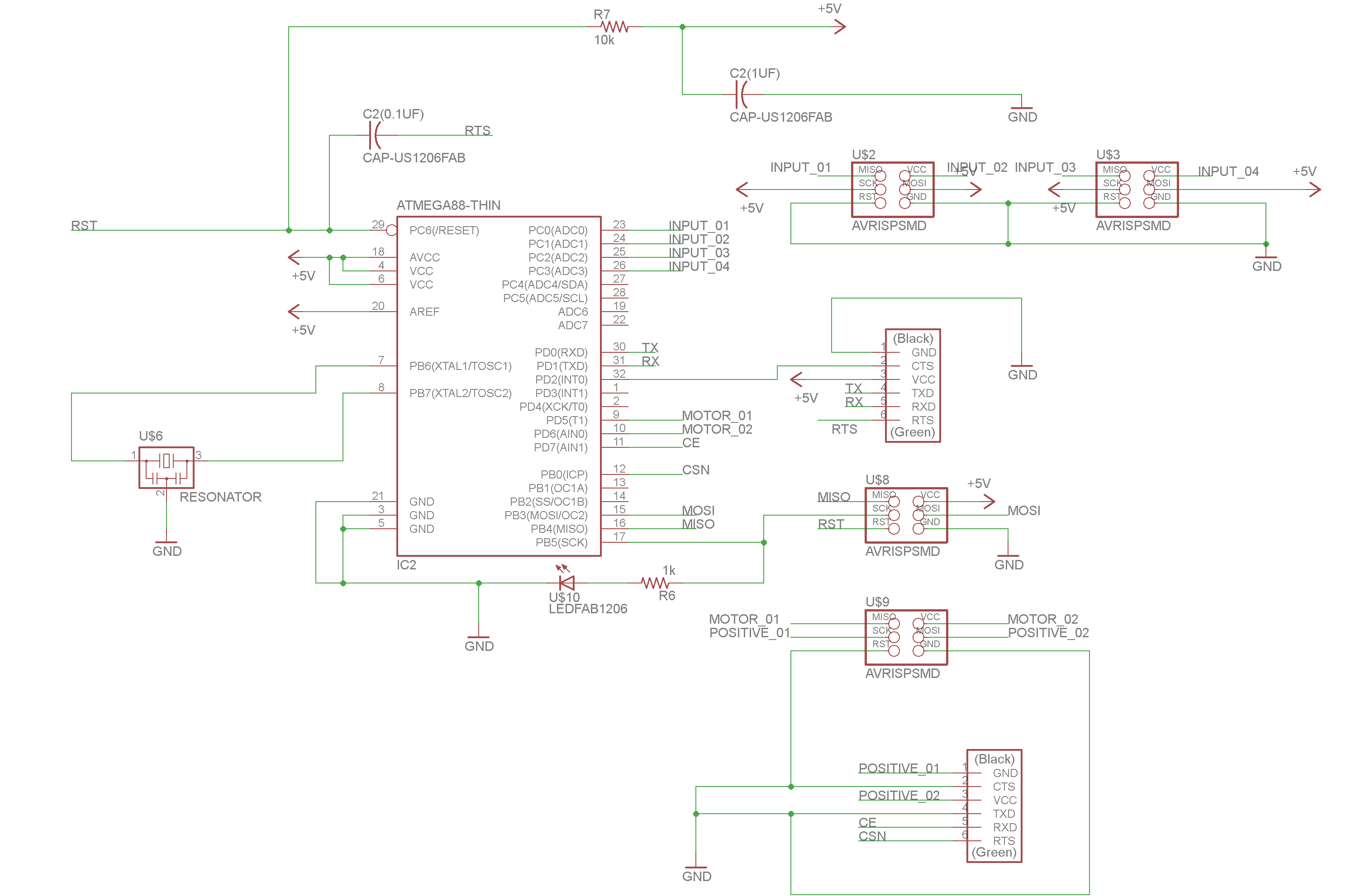
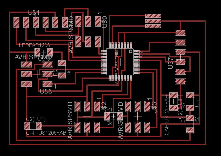
I started from the scheme in "input devices" and "output devices" weeks. This week, I modified my scheme and made several ports for my final project:
- 4 ports to connect 4 phototransistors.
- 2 ports to connect 2 servo motors.
- Also the most important thing, NRF24L01, I identified the pins it needs.
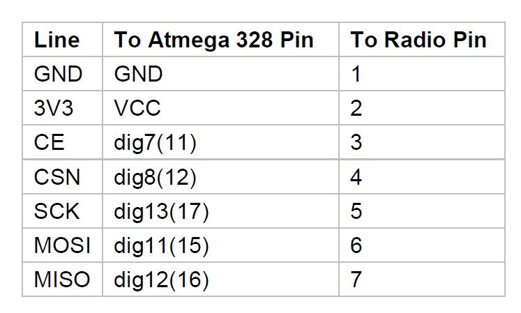 |
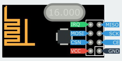
NRF24L01+ pin out:
 |
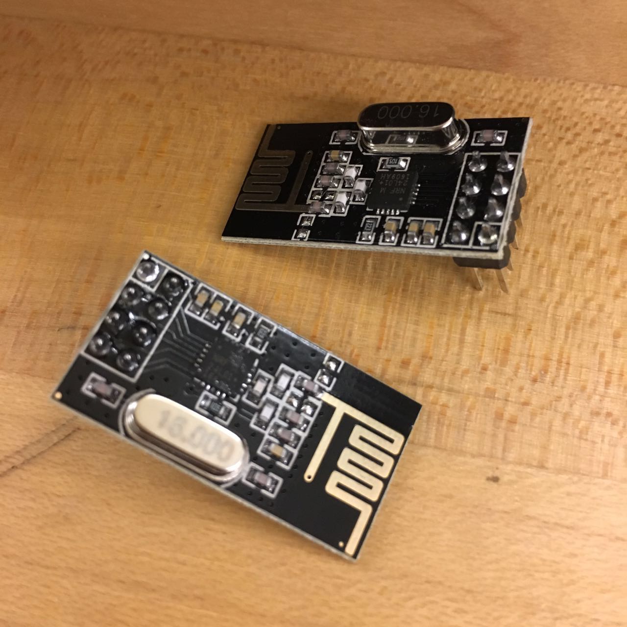
nrf24l01+ I prepared:
 |
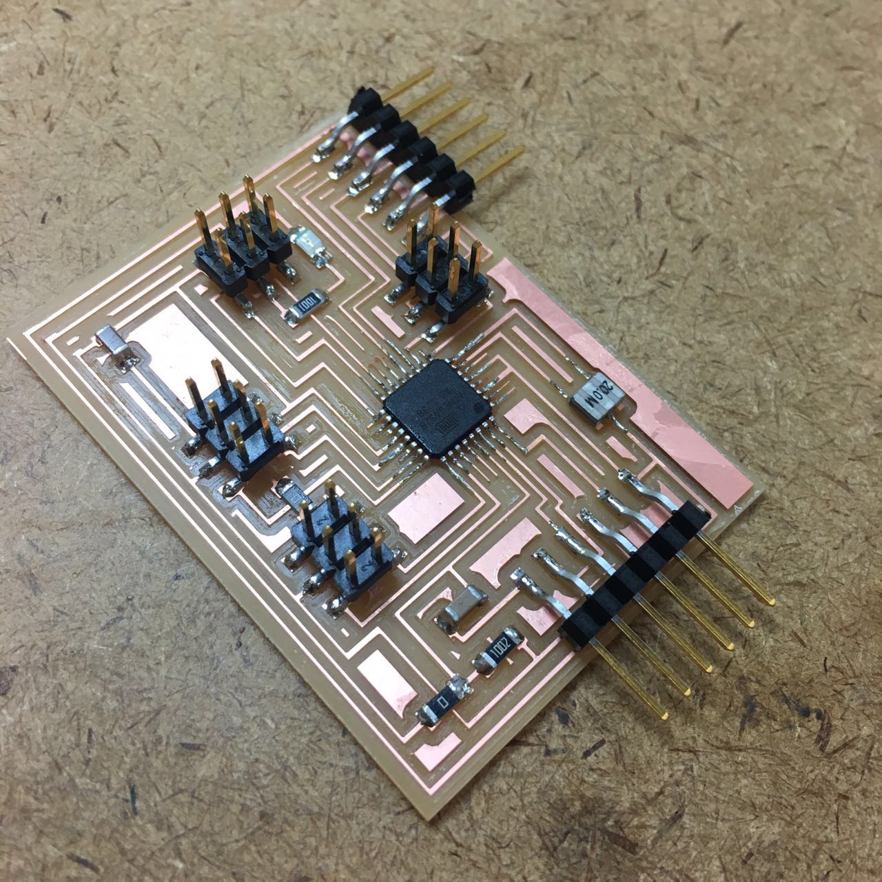
Final scheme:
 |
Final board:
 |
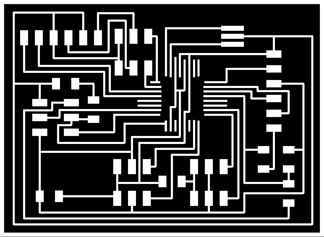 |
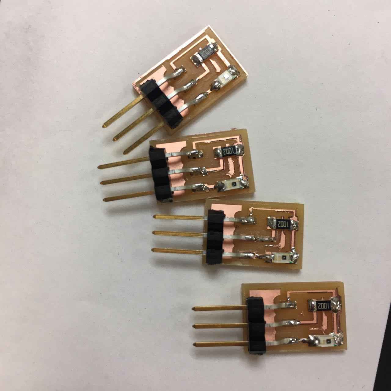
Phototransistor scheme and board:
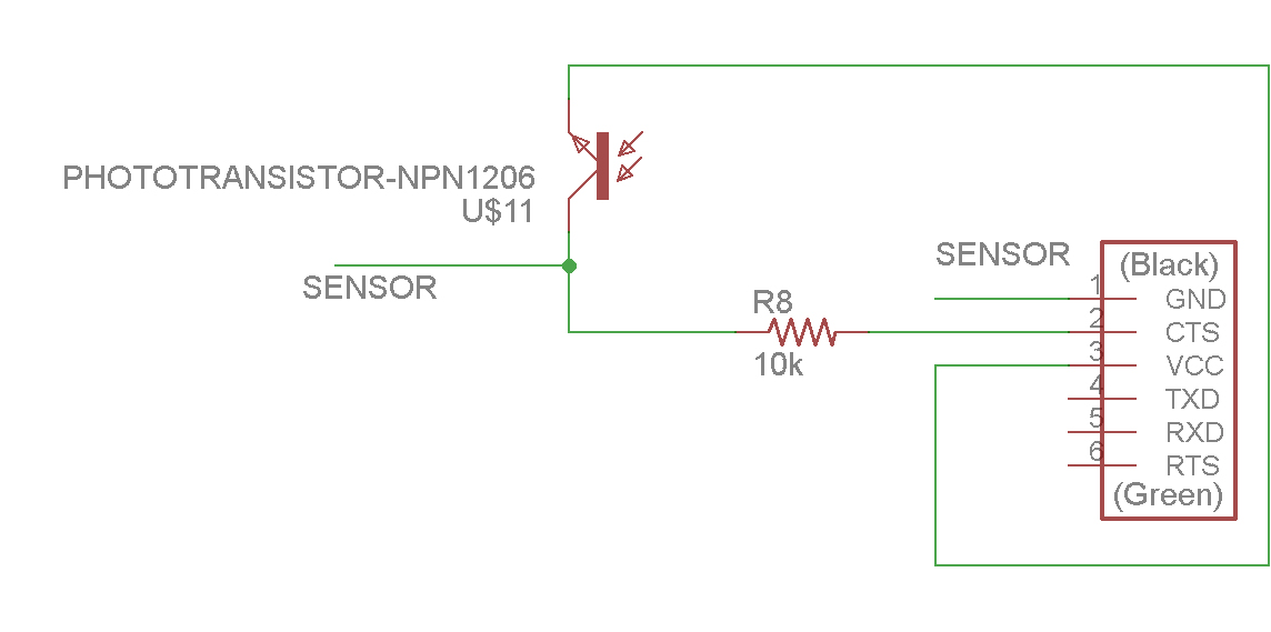 |
 |
Milling and soldering went smoothly.
 |
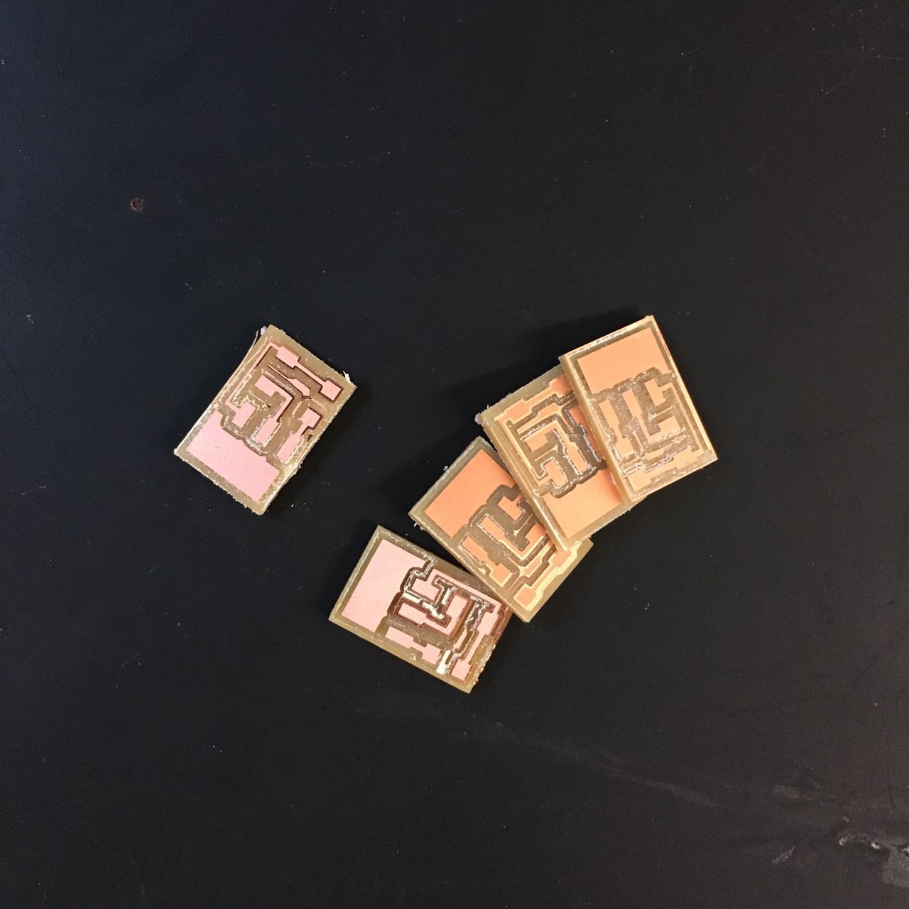 |
 |
 |
Then I started to test in Arduino IDE. I first tested with my 4 phototransistors and 2 servo motors, all the ports worked!
Phototransistor:
 |
Servo motor:
| |
RF24L01+
Then I started to test RF24L01+. I first got the RF24 library from github.
Git hub link: https://github.com/maniacbug/RF24.
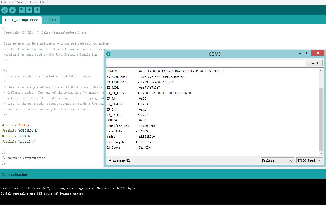
After unzipping the archive into my 'libraries' folder of arduino, I've loaded the RF library in my IDE.I uploaded the sketch of "Examples" - "RF24" - "GettingStarted" as below.
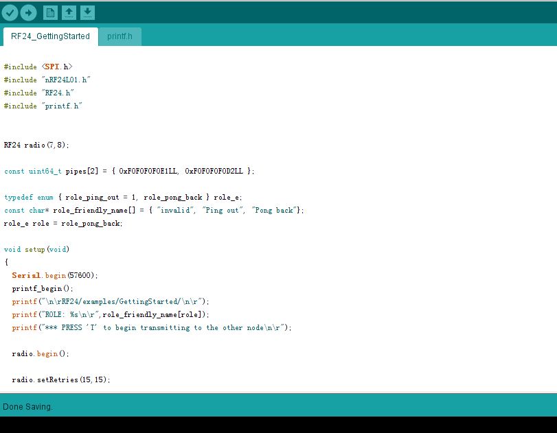 |
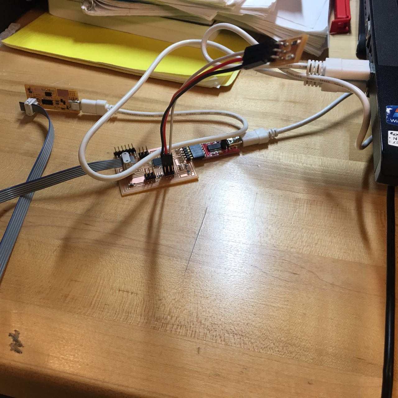
After programming by board, I wired everything up. After a few times of debugging (includding figgure out correct ports and setting up speed), then open the serial monitor, set the speed to 57600. It worked!
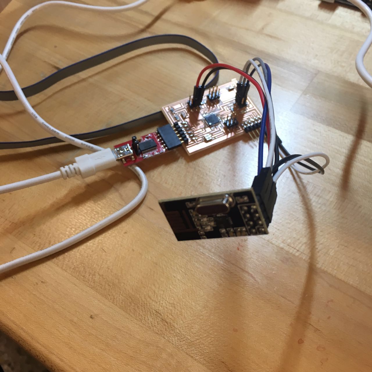 |
 |
Next step is to do the same thing again. I connected another nRF24L01 to an Arduino board to let my board talk to it. I wired up and programmed it, also worked.
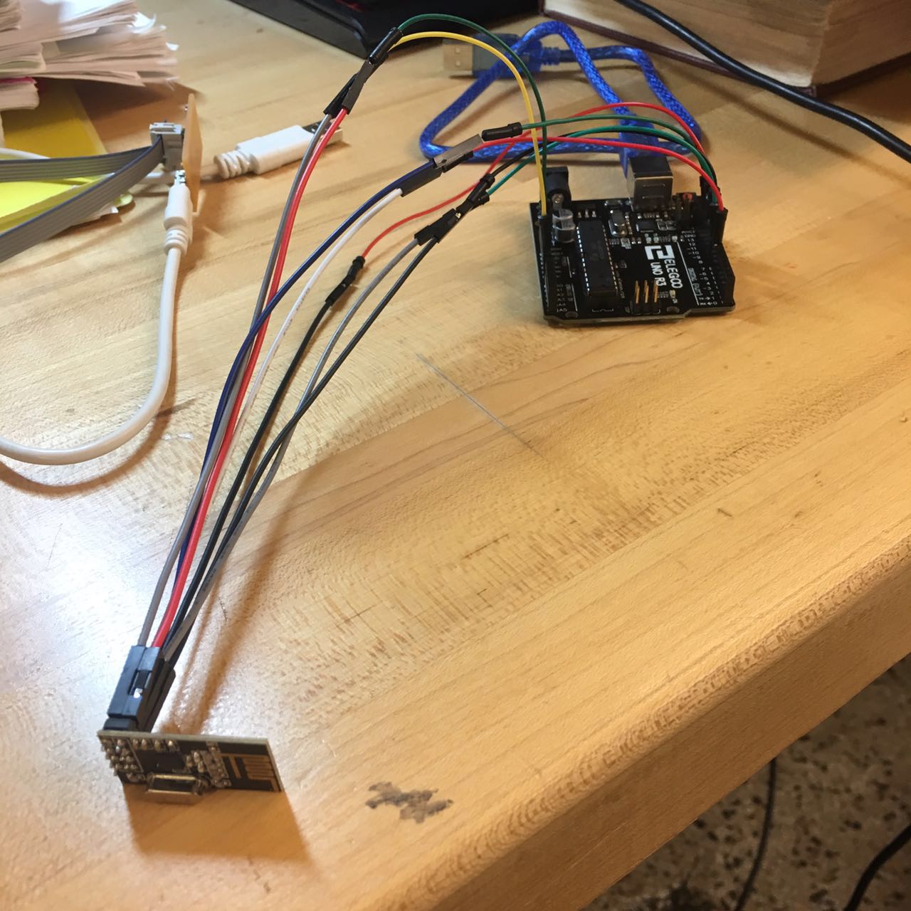 |
Then I typed “T” into the serial monitor to set it into Transmit mode, it started to send numbers. I first got failure to get response.
| |
It turned out to be the problem of USB connection of my board. By re-plugging in, I kept both of the boards running, then I saw two chips happily chatting!
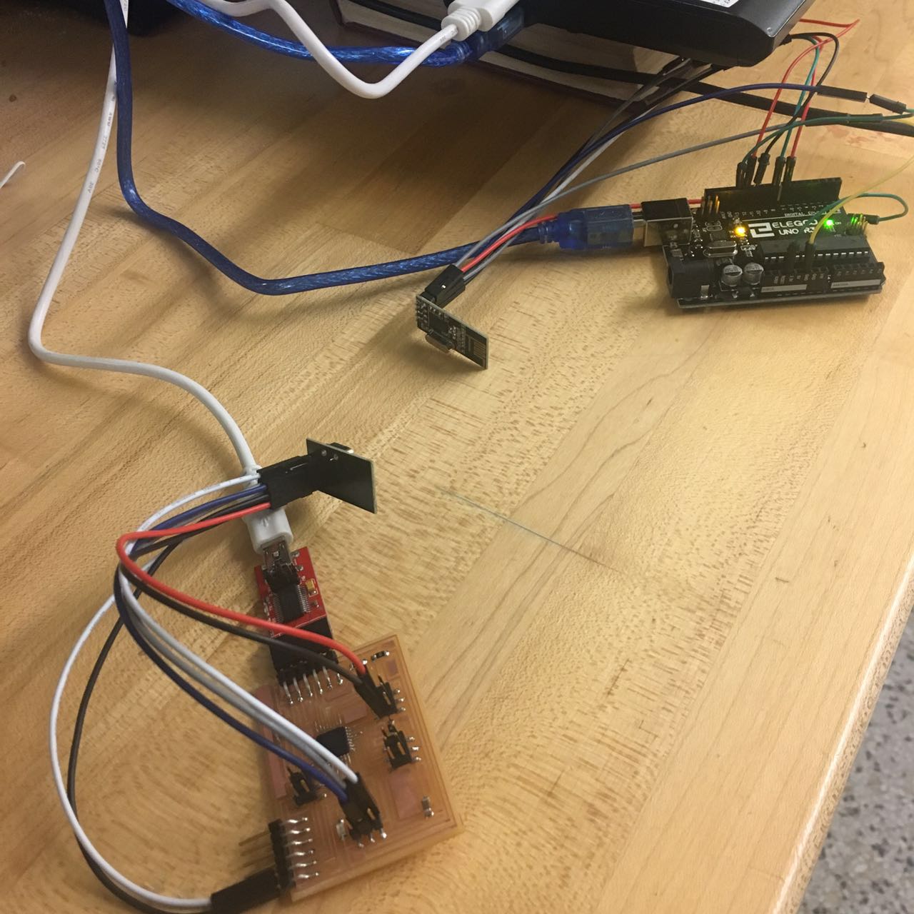 |
| |
(This video was taken by active presenter. It is a very useful tool for screen recording.)