For the Coming Weeks
As finals and last weeks approach, I'm focusing much more on my final project. Those last three weeks will very likely "merge" in the sense that I'll be working torwards having all of the weeks in my final project. Well, interface programming, for my project, requires the networking aspect of the project to be operating. Hence this will I'll also be working with next week's topic - Networking.
Since my final plan is to have a fully connected mods-like system, I'll be designing an integrated physical system that inputs and outputs from the mods server: as in every hello world board, the first step is to have a blinking system that responds to a respective digital mod.
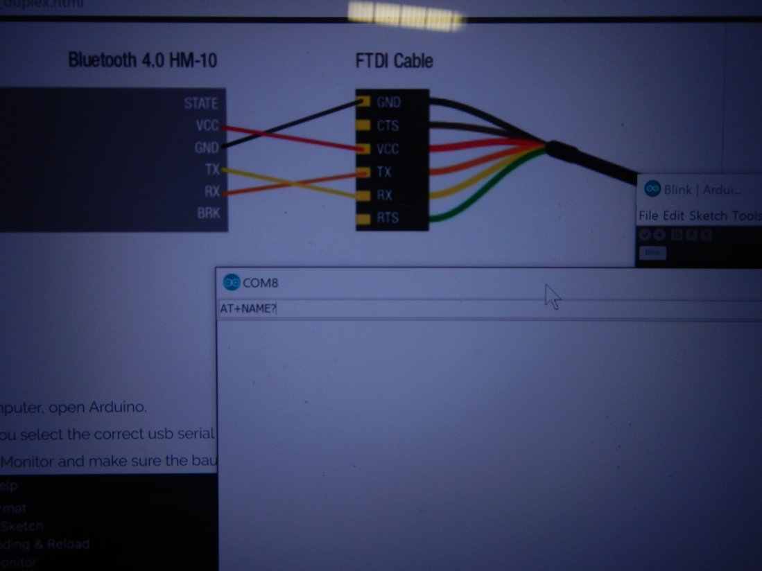
Having decided on which networking-approach my project will have (see the final project page), I started studying bluetooth BLE to come up with a system to connect all of my circuits. Reviewing basic concepts of characteristics, services and addresses was not much complicated. In any case, HTMaA's BLE modules (HM10) worked in a much more impressive and easy way: using the Arduino IDE, it turned out to be as simple as Serial.printing("something").
A website that offered much insight came from one of the class' alumni:
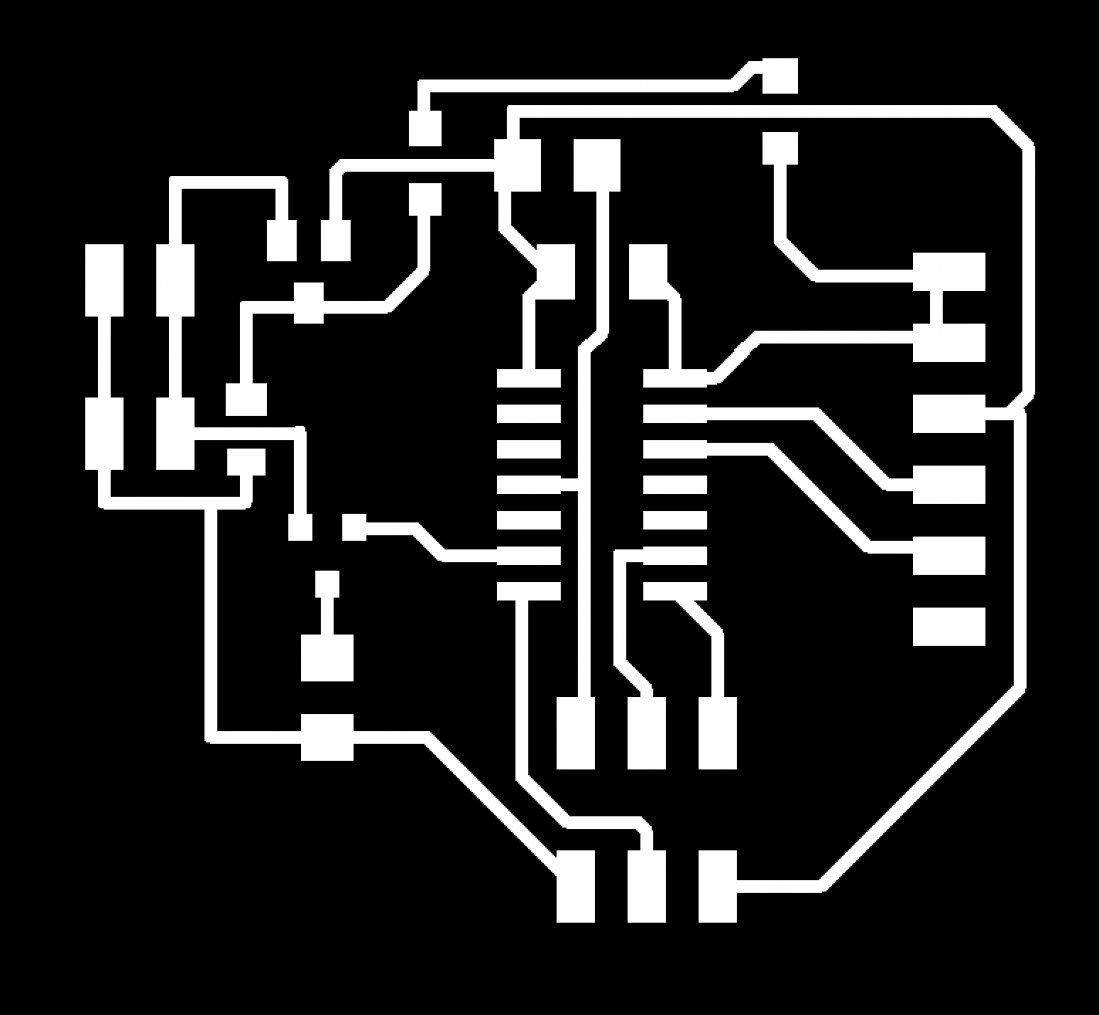
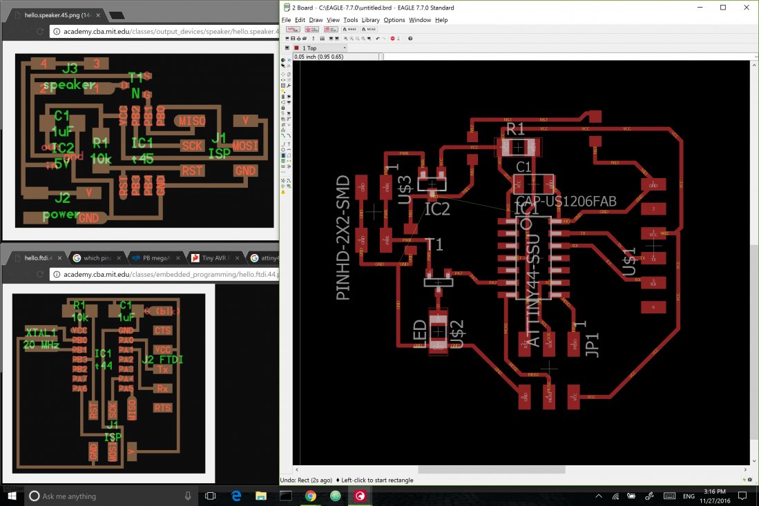
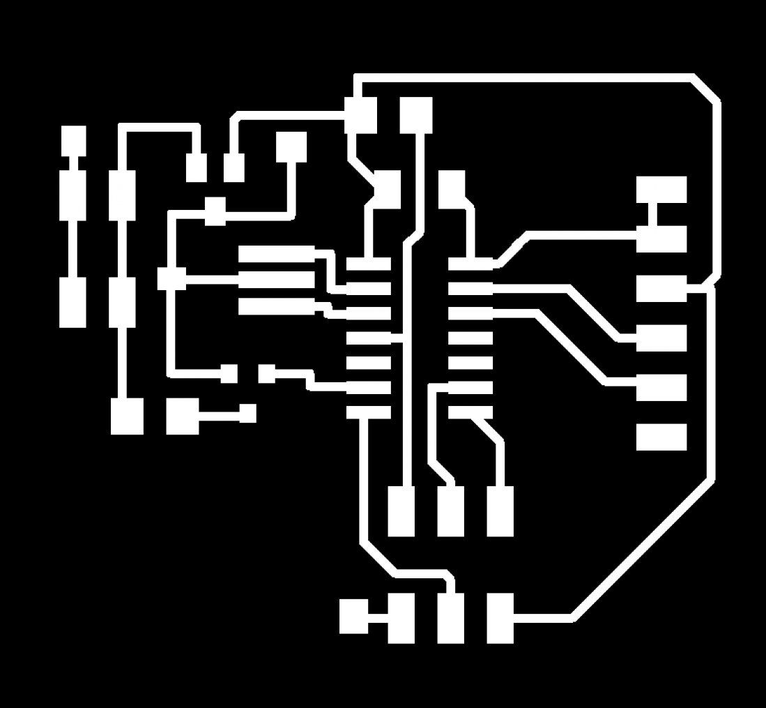
Designing the board was then reduced to merging a board of serial communication with an output board of an LED (since I was using a 12-V 'mini' LED, I had to use concepts learned in the Output Devices week);
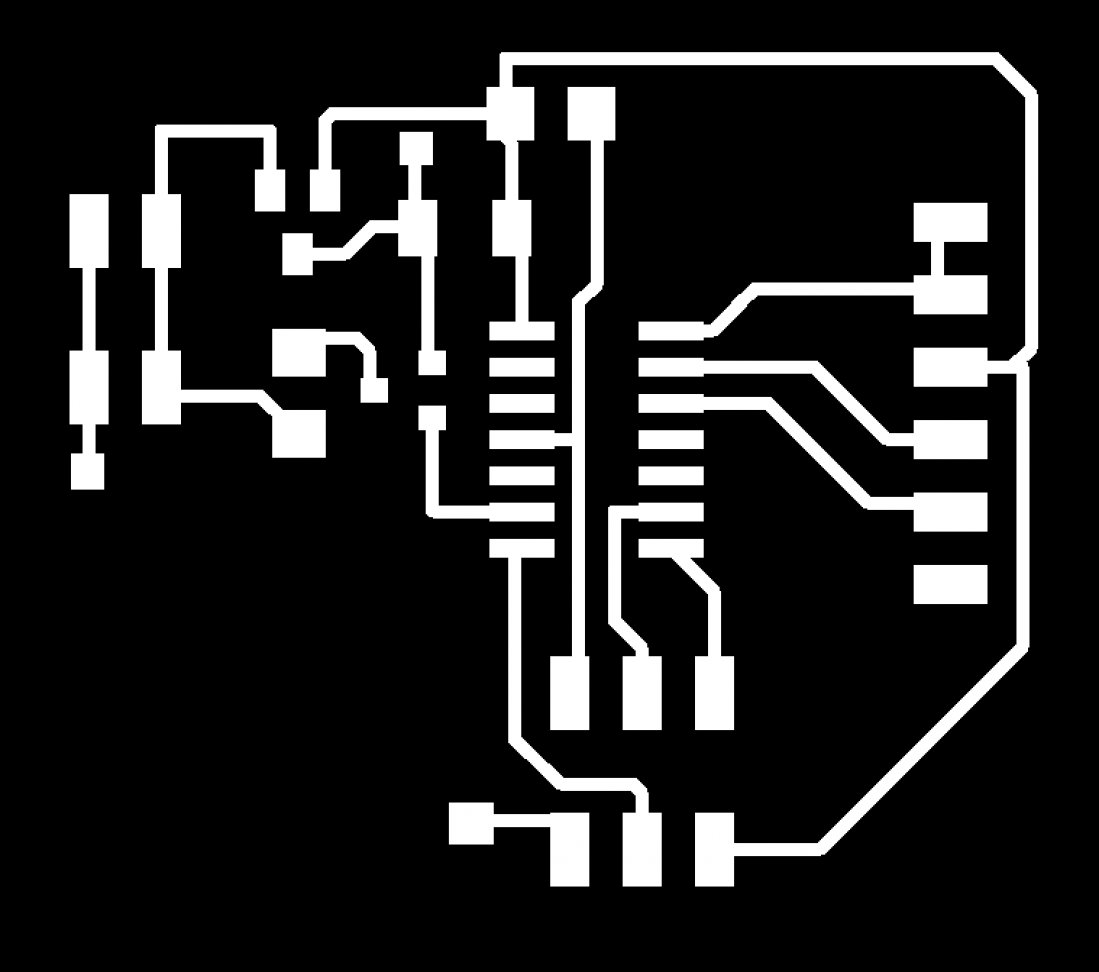
Here's the first version

Milling the board, however, was a big issue (that many people were actually facing that week!): boards were being milled way deeper than they used to be
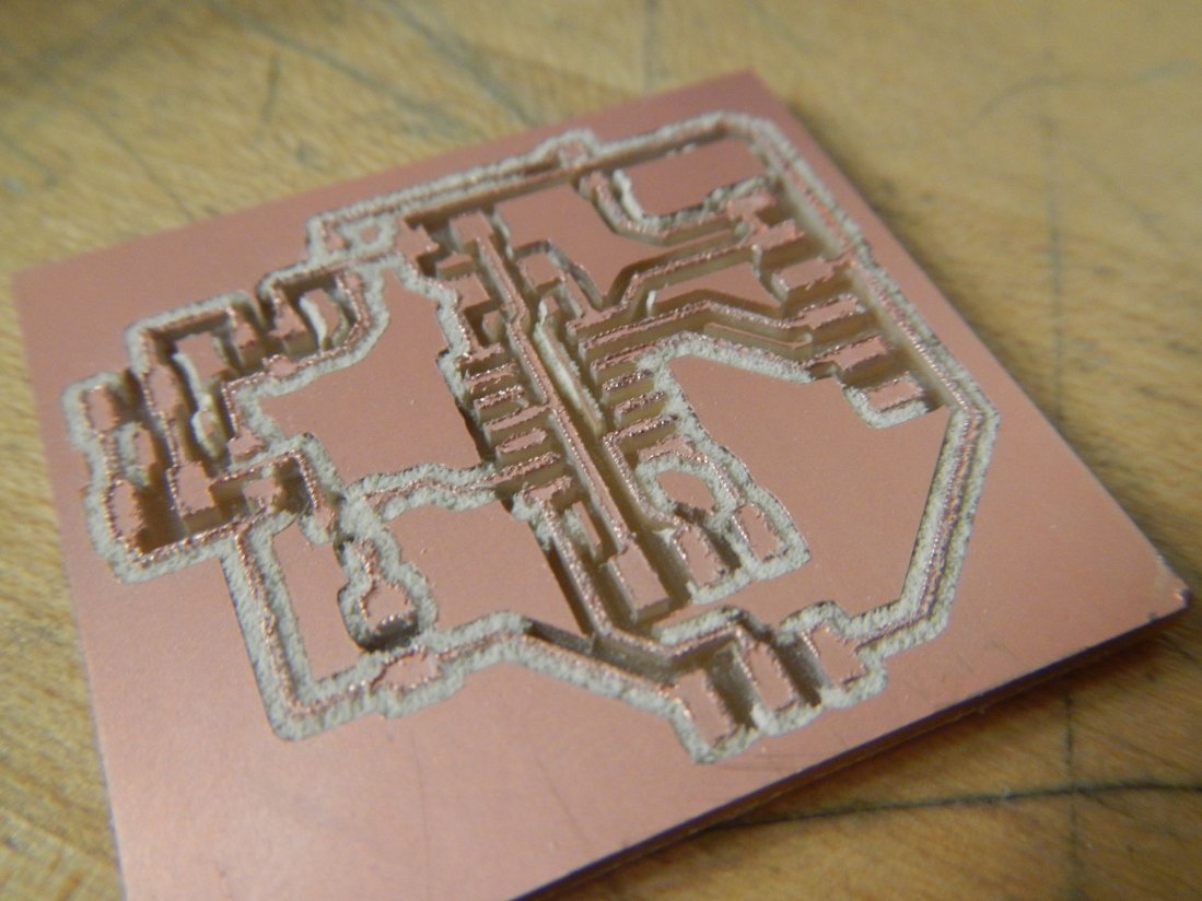
Playing with parameters and testing multiple times, although time consuming, was able to solve the problem. In this specific case, adjusting the depth cut value was enough to solve it.
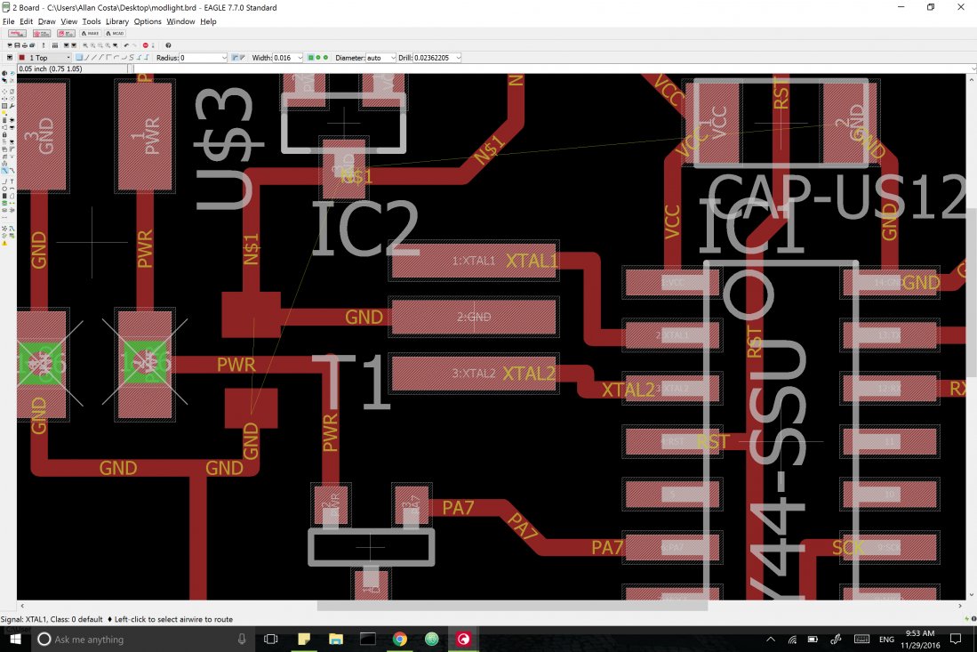
In the middle of the process, I had also redesigned the board (realizing I had confused a P mosfet with an N mosfet again). Here's it:
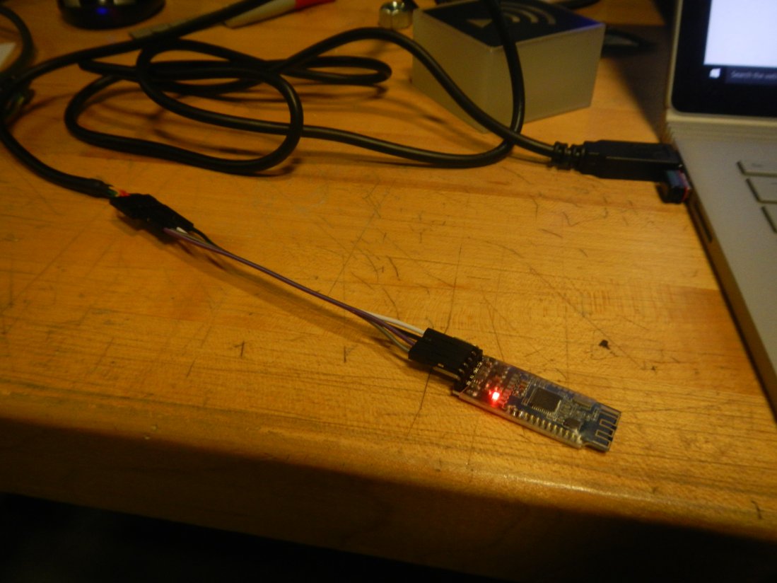
After soldering and uploading some testing codes, I started testing the HM10 module. I first tried the Serial communication approach using an arduino (fast prototyping, right?): the very first approach simply had a Serial communication being established and info being sent:
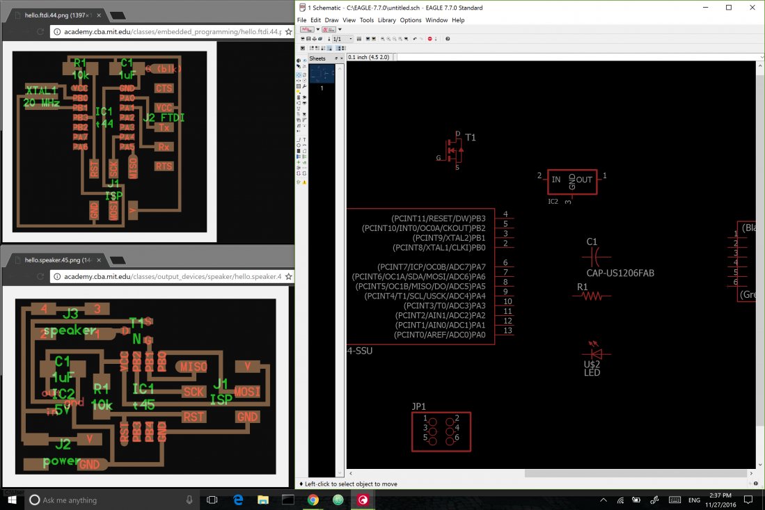
Then, to try it on the board, I uploaded the same Arduino code using the AVRISPII, but nothing happened. I first run into some problems with the Serial: Attiny44 doesn't allow for the common arduino-like approach, it requires you to declare a SoftwareSerial object before using it - but this still didn't work at first. I then uploaded the hello.ftdi code from the Input Devices week, and after some couple re-checks on soldering and updates on the code, I finally got something printed on the screen:
Even though it didn't look like a big thing, I would spend the next two days trying to figure out the problem; the first idea that came to mind was on the very timing of my board; I went back to eagle and redesigned my board, adding a 20MHz crystal to tighen the timing of my baud rate.
And, surprise, it didn't work. I went back to the C code, planning on having more control and trying to have a low-level understanding of the code; I used hello.ftdi's template and added components of hello.blink to have an analog LED on. I would change parameters and re-visit the sheet multiple times, trying to find likely mistakes. If I were to separate the two main functions of my code, PWM and Serial Communication, I would have them working perfectly. This is my board under just PWM:
And this is it communicating through BLE (using the C code, Arduino still didn't solve!):
After getting help from Eric, however, I discovered that hybridizing a PWM function and an serial listener was the most appropriate way to deal with this. The Arduino version of this would have a peripheral simulating an analog input by modulating, but in the case of my code my microcontroller could either listen to serial or modulate an analog - I would have to use a PWM peripheral to process this - and hence the next couple hours were spent trying to understand this not-very-intuitive process.
Arduino's SerialSoftware doesn't work as expected on Attiny44 - the .begin() method was setting up arbitrary values of baud rate and I had spent much time trying to understand where were the errors - as I've seen multiple projects using the Xmega with BLE and Arduino chunks of code, I am still to try a board with it and check if SerialSoftware works appropriately
Some key websites that helped me were recommended by Eric, while some came straight from the FabAcademy. This is the C code that I have at this point
THIS CODE IS NOT FUNCTIONAL - YET :)
  #include < avr/io.h>
  #include < util/delay.h>
  #include < avr/pgmspace.h>

  #define output(directions,pin) (directions |= pin) // set port direction for output
  #define set(port,pin) (port |= pin) // set port pin
  #define clear(port,pin) (port &= (~pin)) // clear port pin
  #define pin_test(pins,pin) (pins & pin) // test for port pin
  #define bit_test(byte,bit) (byte & (1 << bit)) // test for bit set
  #define bit_delay_time 8.5 // bit delay for 115200 with overhead
  #define bit_delay() _delay_us(bit_delay_time) // RS232 bit delay
  #define half_bit_delay() _delay_us(bit_delay_time/2) // RS232 half bit delay
  #define char_delay() _delay_ms(10) // char delay
  #define serial_port PORTA
  #define serial_direction DDRA
  #define serial_pins PINA
  #define serial_pin_in (1 << PA0)
  #define serial_pin_out (1 << PA1)

  #define led_port PORTA
  #define led_pin (1 << PA7)
  #define led_direction DDRA


  #define max_buffer 25
  int value = 0;
  void get_char(volatile unsigned char *pins, unsigned char pin, char *rxbyte) {
    //
    // read character into rxbyte on pins pin
    //    assumes line driver (inverts bits)
    //
    *rxbyte = 0;
    while (pin_test(*pins,pin))
       //
       // wait for start bit
       //
       ;
    //
    // delay to middle of first data bit
    //
    half_bit_delay();
    bit_delay();
    //
    // unrolled loop to read data bits
    //
    if pin_test(*pins,pin)
       *rxbyte |= (1 << 0);
    else
       *rxbyte |= (0 << 0);
    bit_delay();
    if pin_test(*pins,pin)
       *rxbyte |= (1 << 1);
    else
       *rxbyte |= (0 << 1);
    bit_delay();
    if pin_test(*pins,pin)
       *rxbyte |= (1 << 2);
    else
       *rxbyte |= (0 << 2);
    bit_delay();
    if pin_test(*pins,pin)
       *rxbyte |= (1 << 3);
    else
       *rxbyte |= (0 << 3);
    bit_delay();
    if pin_test(*pins,pin)
       *rxbyte |= (1 << 4);
    else
       *rxbyte |= (0 << 4);
    bit_delay();
    if pin_test(*pins,pin)
       *rxbyte |= (1 << 5);
    else
       *rxbyte |= (0 << 5);
    bit_delay();
    if pin_test(*pins,pin)
       *rxbyte |= (1 << 6);
    else
       *rxbyte |= (0 << 6);
    bit_delay();
    if pin_test(*pins,pin)
       *rxbyte |= (1 << 7);
    else
       *rxbyte |= (0 << 7);
    //
    // wait for stop bit
    //
    bit_delay();
    half_bit_delay();
    }

  void put_char(volatile unsigned char *port, unsigned char pin, char txchar) {
    //
    // send character in txchar on port pin
    //    assumes line driver (inverts bits)
    //
    // start bit
    //
    clear(*port,pin);
    bit_delay();
    //
    // unrolled loop to write data bits
    //
    if bit_test(txchar,0)
       set(*port,pin);
    else
       clear(*port,pin);
    bit_delay();
    if bit_test(txchar,1)
       set(*port,pin);
    else
       clear(*port,pin);
    bit_delay();
    if bit_test(txchar,2)
       set(*port,pin);
    else
       clear(*port,pin);
    bit_delay();
    if bit_test(txchar,3)
       set(*port,pin);
    else
       clear(*port,pin);
    bit_delay();
    if bit_test(txchar,4)
       set(*port,pin);
    else
       clear(*port,pin);
    bit_delay();
    if bit_test(txchar,5)
       set(*port,pin);
    else
       clear(*port,pin);
    bit_delay();
    if bit_test(txchar,6)
       set(*port,pin);
    else
       clear(*port,pin);
    bit_delay();
    if bit_test(txchar,7)
       set(*port,pin);
    else
       clear(*port,pin);
    bit_delay();
    //
    // stop bit
    //
    set(*port,pin);
    bit_delay();
    //
    // char delay
    //
    bit_delay();
    }

  void put_string(volatile unsigned char *port, unsigned char pin, char *str) {
    //
    // print a null-terminated string
    //
    static int index;
    index = 0;
    do {
       put_char(port, pin, str[index]);
       ++index;
       } while (str[index] != 0);
    }

  int main(void) {
    //
    // main
    //
    static char chr;
    static char buffer[max_buffer] = {0};
    static int index;
    //
    // set clock divider to /1
    //
    CLKPR = (1 << CLKPCE);
    CLKPR = (0 << CLKPS3) | (0 << CLKPS2) | (0 << CLKPS1) | (0 << CLKPS0);
    //
    // initialize output pins
    //
    set(serial_port, serial_pin_out);
    output(serial_direction, serial_pin_out);
    //
    // initialize led pins
    //

    TCCR0A = (1 << COM0B1) | (0 << COM0B0) | (0 << WGM01) | (1 << WGM00); // clear OC0B on compare match
    TCCR0B = (1 << CS02) | (0 << CS01) | (1 << CS00) | (1 << WGM02); // prescaler /1024,
    //
    TCNT0 = 0x00;
    OCR0A = 0xC3;
    OCR0B = 0x05;
    //
    PORTA |= (1 << PA7);
    DDRA |= (1 << PA7);
    //
    //
    set(led_port, led_pin);
    output(led_direction, led_pin);
    //
    // main loop
    //
    index = 0;
    value = 100; // testing an arbitrary "analog output"
    while (1) {
       OCR0B = value;
       get_char(&serial_pins, serial_pin_in, &chr);
       put_string(&serial_port, serial_pin_out, "hello.ftdi.44.echo.c: you typed \"");
       buffer[index++] = chr;
       if (index == (max_buffer-1))
          index = 0;
       put_string(&serial_port, serial_pin_out, buffer);
       put_char(&serial_port, serial_pin_out, '\"');
       put_char(&serial_port, serial_pin_out, 10); // new line
       }
    }
WebSockets
The actual networking part of the week was mostly focused on trying to understand and implement websockets, specifically for the case of BLE. And again, I didn't know on how much trouble I was putting myself when I started searching on ways to go through the barrier Web-Local.
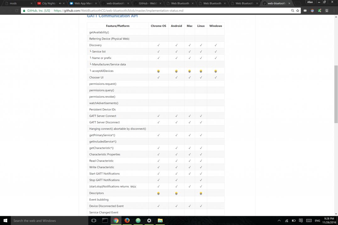
Many technologies are being developed (ish) in the area of having plugins, USB and BLE communicating straight from the web. Google Chrome's Web BLE plugin was a terrible starting point. It was just after a whole hour reading the the plugin's git page that I discovered it was just cancelled for Mac, Windows and Linux platform.
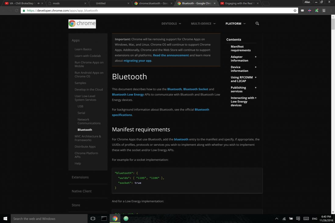
Moreover, documentation is an impressive lacking state: YouTube searchers won't return a single video explaning on implement it, and most of searches on Google would return pages that clearly stated that their documentations were obsolete. Anyway:
Not being able to use either Chrome or Firefox's plugins, I decided to use the mods-like pure JS approach to create WebSockets and access the USB data coming (which was by itself being sent through BLE from other boards). Here's the testing of serial communication (in this case, I'm using BLE from an arduino for I've run into multiple issues with my own board - see above)
Although I have had enough experience with BLE by playing with it, I ended up using Wi-Fi to set up my final project. BLE turned out to be more troublesome than I expected, and, reconsidering my final project's own software structure, it makes much more sense for me to have Wi-Fi-based IoT devices (see the The Mods section of my final project).
Hacking Mods
It's been almost half of the interface week, and I've just realized I'm running out of time for interfacing itself.
Again, for a fundamental part of my project is based on using mods (or at least a 'hacked' version of it), my interface programming will be on using mods to represent circuit, in such a way that the virtual, digital inputs and outputs of mods will rather represent physical inputs and outputs in my circuits.
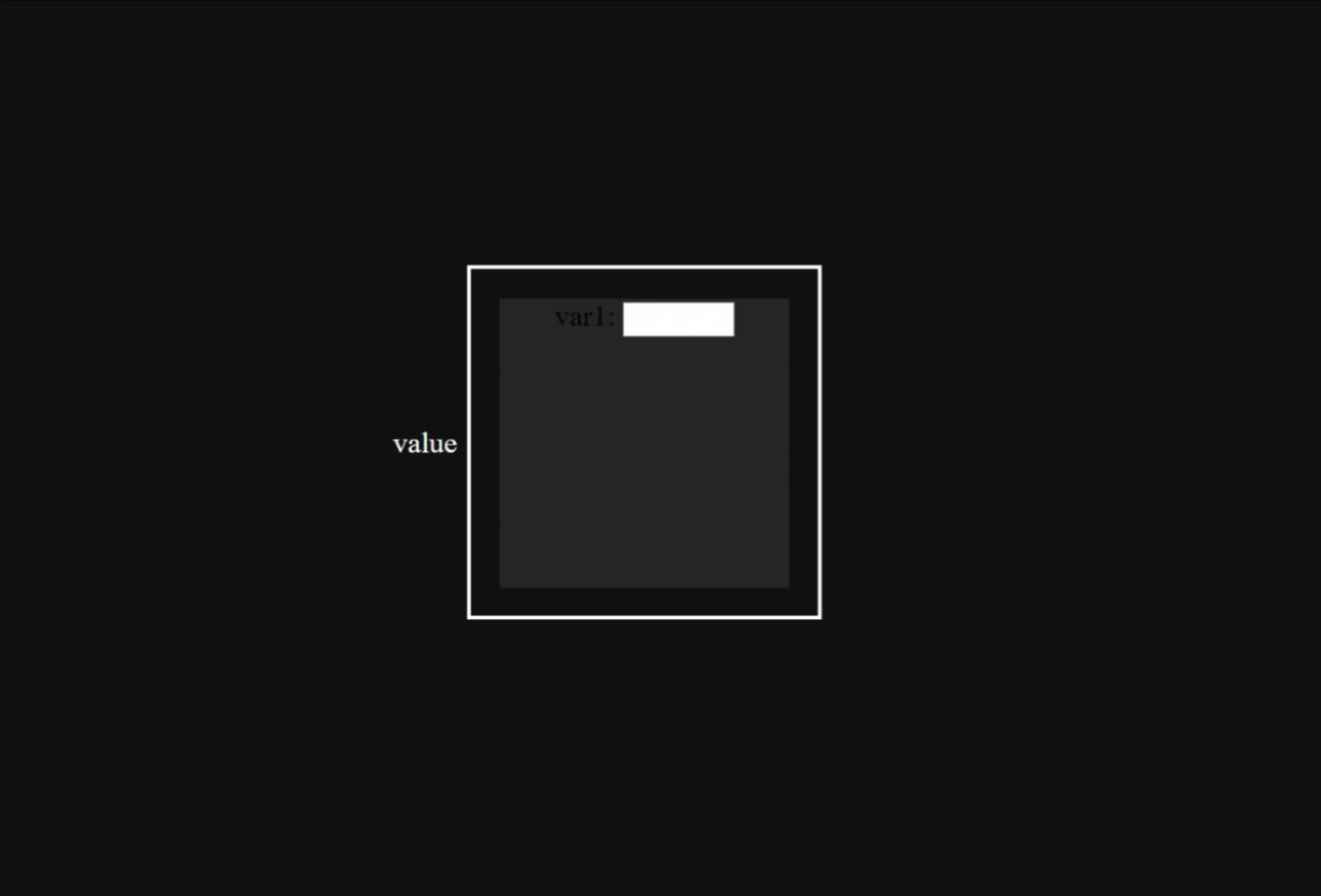
First, I spent some time exploring mods, playing with its programs and reading its .js core. After downloading and playing a bit more with it for a while, I started modifying its interface: first thing to consider was minimalism - reducing the size of the modules by setting up a system to get them compacted and add the option to have it in a reduced state. Following the a minimalistic and touch-screen-adapted set of design rules (see final project), I slowly adapted the javascript code to get to the interface. A simple module would then be as clean as:

A nice aspect of this is having responsiveness playing a major role in changing parameters and modifying modules. In other words, modules would naturally be small, simple squares represented by a symbol and a title (I've drawn many ideas from the very concept of a simple GUI); however, similar to opening a folder, a given mod can be "expanded" and have its parameters, now visible, modified as needed.
This also implies that adding mods and removing them should be as easy as dragging and expanding screen elements: I hence added a small footer that will contain all the mods; an user can add a new mod by dragging it from the menu, and can remove it from the interface by placing it back there; this is the final interface:
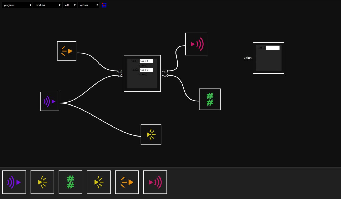
Now the interfacing part is much simpler; now considering my WiFi approach (see above!), I'll set up a simple database (maybe a .csv file, or a simple API) to hold information from my circuits, and then I'll simply need to create the modules that will handle post and get requests, as well as process the data. Still lacking appropriate URLs, the code for the module will be:
    (function(){
    var mod = {}
    var name = 'lightemitter'
    var init = function() {
      mod.value = 0;
     }
    var inputs = {
      value: {type:"integer",
      event: function(evt){
         mod.value = evt.detail
         post_value(mod.value)
       }
     }

    }
    var outputs = {
      }
    var interface = function(div){
      mod.div = div
      div.appendChild(document.createTextNode('var1: '))
      input = document.createElement('input')
         input.type = 'text'
         input.size = 6
         div.appendChild(input)
         mod.emitter = input.value
    }
    function post_value(value) {
        var root = ""
        var parameters = ""
        var webpage = root + parameters;
        var request = window.setInterval(function(){
          jsonp(webpage, 'callback', function(json){clearInterval(request)})}, 5000);

    }
    function jsonp(url, key, callback) {

        var appendParam = function(url, key, param){
                return url
                    + (url.indexOf("?") > 0 ? "&" : "?")
                    + key + "=" + param;
            },

            createScript = function(url, callback){
                var doc = document,
                    head = doc.head,
                    script = doc.createElement("script");

                script
                .setAttribute("src", url);
                head
                .appendChild(script);

                callback(function(){
                    setTimeout(function(){
                        head
                        .removeChild(script);
                    }, 0);
                });
            },
            q =
                "q" + Math.round(Math.random() * Date.now());
        createScript(
            appendParam(url, key, q), function(remove){
                window[q] =
                    function(json){
                        window[q] = undefined;
                        remove();
                        callback(json);
                    };
            });
    }
    return ({
       name:name,
       init:init,
       inputs:inputs,
       outputs:outputs,
       interface:interface
       })
    }())
I'll spend most of next week playing and studying Wi-Fi: I'll then be in good position to start implementing the interfacing appropriately.