Merging Ideas
There were two key things that merged to form my idea for the final project. At first, I was much interested in continuing a long-planned project of creating a museum-like educational touch table that would visualize the "tree of life" - basically making it funnier and more interesting for high schoolers to learn phylogenetics.
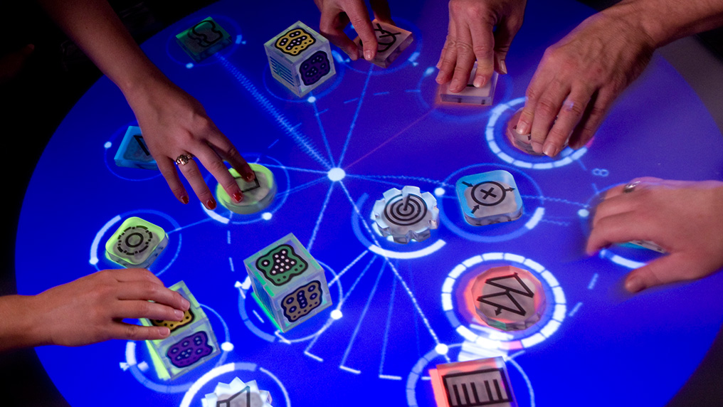
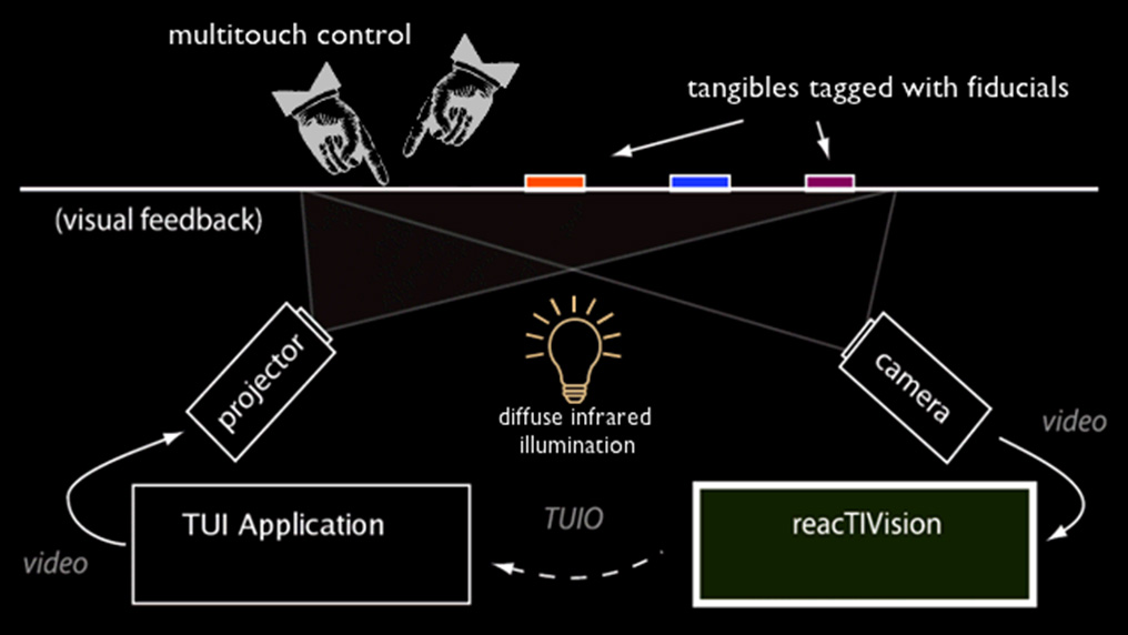
I had indeed started and gone much deeper with this plan, which was slowly developed by a team of three friends. However, the original idea was to have the system as an app: the idea of maybe having a huge interactive table came from another product, the ReacTable:
The second key influence to my final project was my UROP at the Center for Bits and Atoms. Inspired on the Fab Mods, my UROP project is to develop a set of biological data processing tools that will use the same interfacing and processing as mods. The original project plan was to have something completely digital, but after some weeks of polishing and brainstorming, the idea of having our system integrated with multiple physical components (compare this, for instance, to mods communicating with a milling machine) came into play.
A key challenge naturally emerged: binding data. As bio lab work often involves multiple machines, chambers, components etc., we would have to communicate not only with a single measuring device, but with multiple, network-integrated components. Not surprisingly, the challenge soon became the issue of having networked devices' data being interfaced and processed following the user's necessity and plans: we would have to adapt mods to become an IoT-devices core, where a user would especify which machines would be communicating, which kind of data would be flowing and how such data would be processed. The one thing we were lacking was the answer to the question of how to implement a user-friendly, intuitive and centralized interface where measuring devices and IoT tools would be represented.
The bio-mods project provided me the mathematical ideas and concepts, as well as the very environment of having something based on a laboratory and interfaced via Mods, while the educational table project gave me ideas on the user interaction, design and representation concepts I'd need to abstract all of this.
At this point you've probably noted that I'm really interested in networks and interaction with those.
The Data Nexus
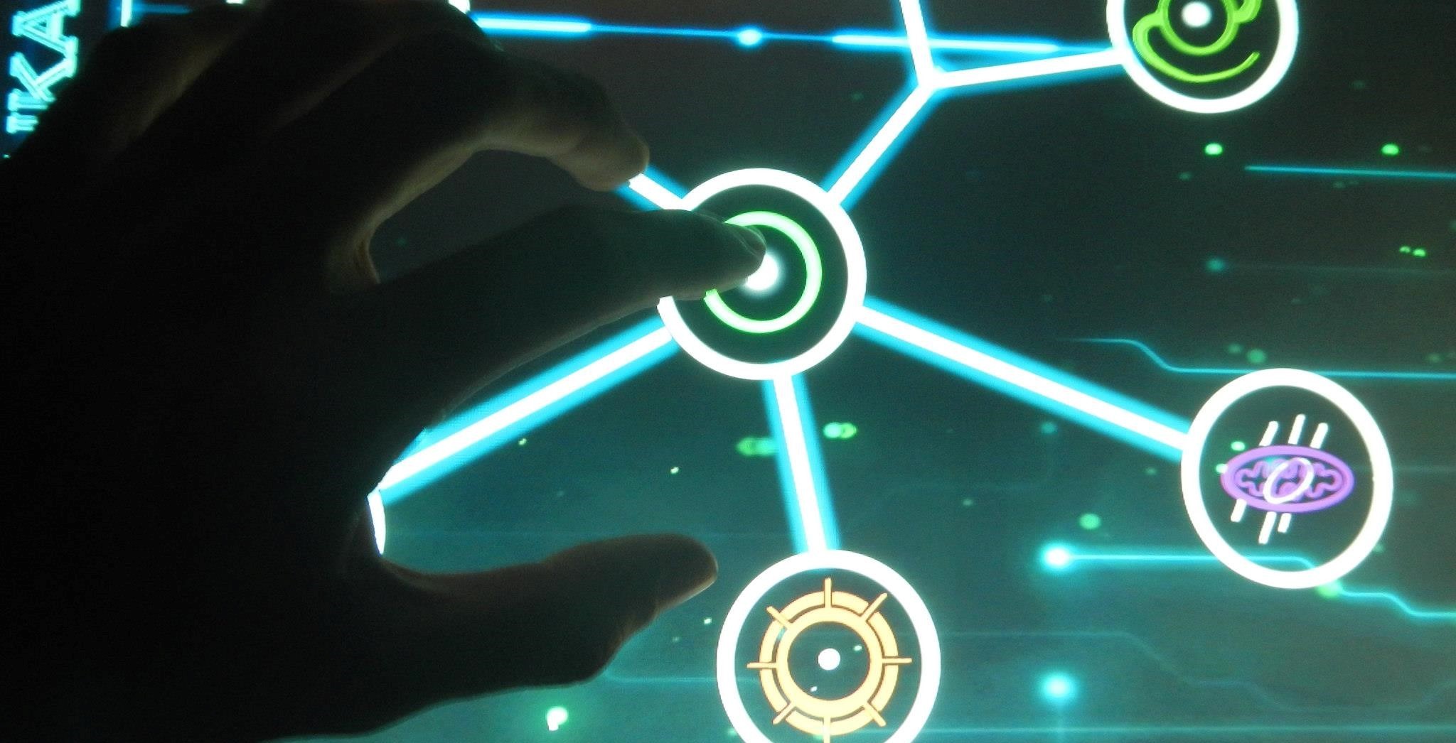
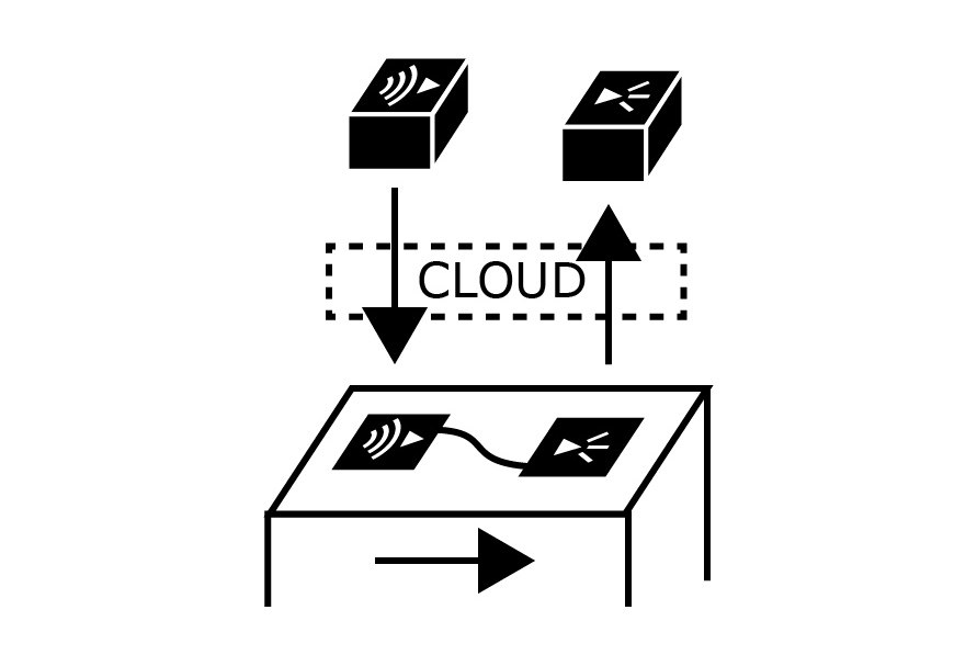
The final product will be the Data Nexus, a live data-processing touch table. It will be a smart lab bench that communicates with external electronics components, while gathering their data and having it applied to data processing tool. Drawing from the Mods idea, "Physical Mods" will be the physical equivalent of digital modules, and will do computation through circuitry. The main idea is to have components that, once over the table, will be detected and drawn into a digital representation. The user will them be able to alter parameters of the digital representation which will, on the other hand, provide feedback to the physical version. The key aspect of the project is then on having multiple of those physical modules: by using systems such as FabMods, we will then be able to link multiple of those in the digital universe - meaning we will be creating links between their physical counterparts. In other words, this table will get data from multiple devices and then allow the user to decide on what to do with it.
Of course, this is part of a much bigger project - and for it to be manageable for the class, I'll be developing just some of the mods for this first version of the table. Namely, for demonstration purposes, I plan to create an standardized, modular approach for handling and interfacing the physical mods with the table, and the table with the digital mods. As a final minimum viable product, I plan to have at least five physical, a touchscreen (and maybe mod-detecing screen) table, a simple database and a hacked version of mods through which the user will interact.
The physical mods I plan to design and build are five: three of them are output mods (two of them will output light and the other one will output sound), and two input mods (one for measuring distance and other for detecting sound) - for the final demonstration, I should have a music file being output by a sound output mod while being regulated by a distance input mod. This sound will be captured by a sound input mod, and this data will be further processed (I'll try to separate sound patterns according to pitch) into two different chains of digital mods, eventually ending up in respective light output mods. < Spoiler Alert from the Allan of the Future: I run out of time > .
A Bit of Learning
Instructables has much to offer for this project. I ended up learning much on building a touch screen table from those two projects: Multi-touch Table , which is not very well documented but did an amazingly cheap project and ended up providing me many insights on the steps to follow; and Creating your First Multi-touch Table, which counts with an impressively well documented report (maybe too documented!), but that created such a high-quality final product that turned out to be economically impossible for me (as a humble sophomore hah) to do.
I also found much of documentation, tinkering by searching on ReacTable; a simple search on google should return multiple results of those - particularly helpful were diagrams Google Images provided on how the table works is powered and has touch detected.
The Table Structure
This section of the final project was also part of a Week 6 assignment. Check it for more details (and by that I mean failures).
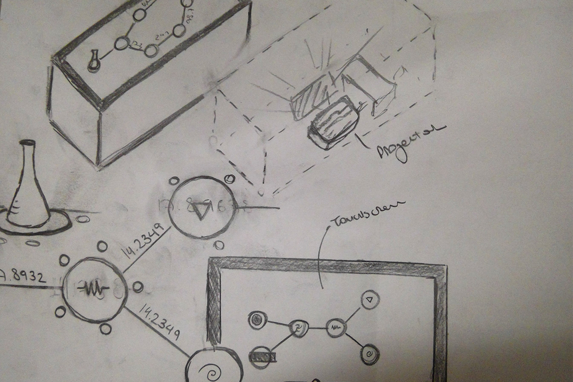
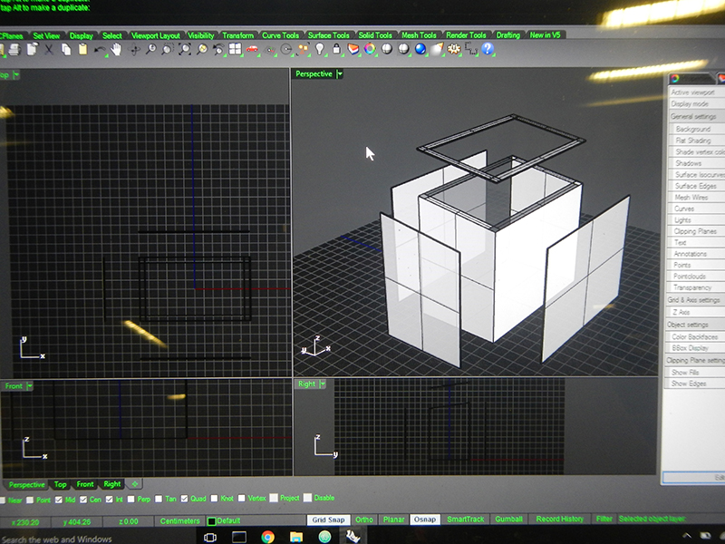
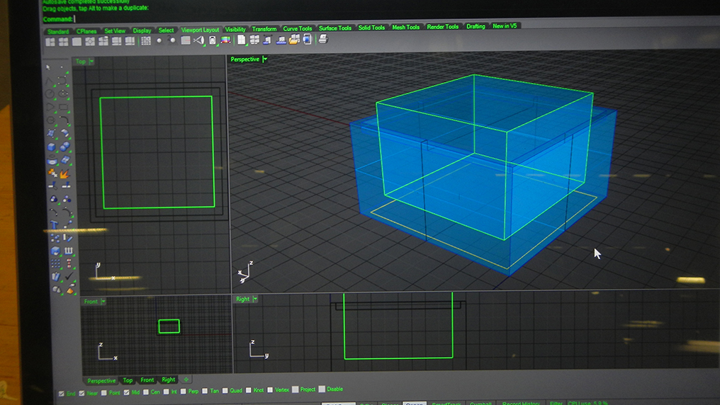
I designed most of the structure by iterating between a sheet of paper, a cup of coffee and Rhino. The design of the table structure was based mostly on usability: I was planning on having a stretched-like screen (maybe resembling a more lab bench-kind of structure), but I wanted to be able to see the content on the screen from far (meaning I would have to have a small inclination on the upper part of it). I further planned on having something comfortable for arms not to have to strech and reach (something not tall enough to be uncomfortable, but not small enough for people to have to move to reach it - note that I'm using my own height here too). The final design wasn't too different from an interactive museum table:
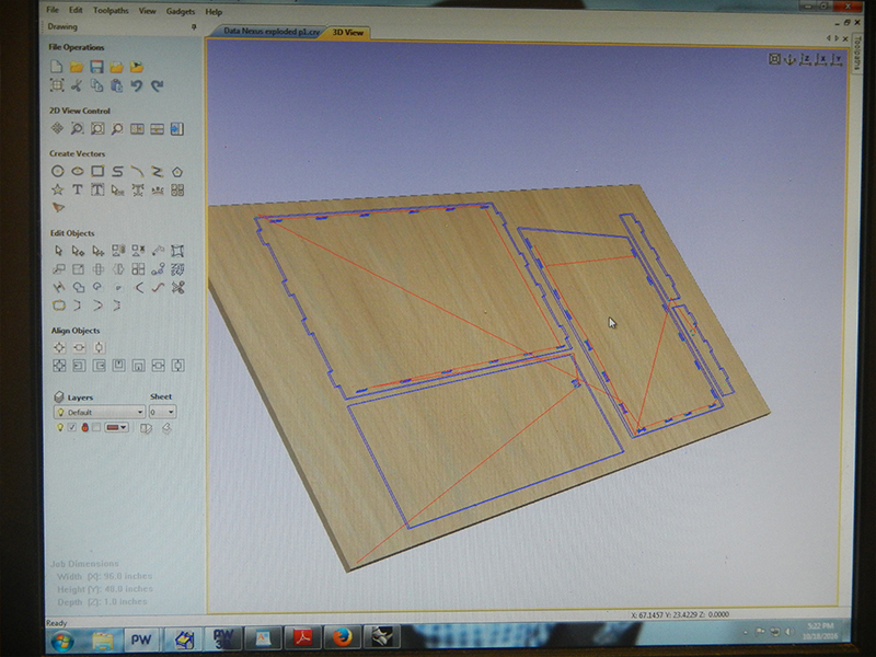
As described in Week 6, I small issue emerged when I discovered we were limited by the number of sheets of wood (for some reason, I thought we could use more than one sheet of OCB). Since my original design had been designed over three sheets, I had to solve the problem by removing some of the parts and resizing the remaining ones. Not surprisingly, the joints didn't fit as expected, but I found a workaround by manually pressing some of the joint parts or cutting part of them to fit.
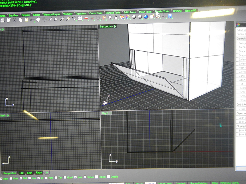
Four weeks later, having already built the screen and the physical mods, I returned to the table structure to complete the missing parts: this time, I used the remaining sheets that were not used by other people during week 6. In one of those great coincidences that happen during project building, it just happened that I changed the screen size I was originally aiming to use: the missing pieces of the table had originally been designed to hold the original screen size. Hence, by not having the table complete before, I avoided having to rebuild it, and rather just had to find a workaround that single issue. The challenge now was to build the piece that would hold the screen itself: at that point, and throughout the process of building the screen, I had used a simple aluminum structure to hold and test it; it was time to design something more legit that would be an integral part of the table.
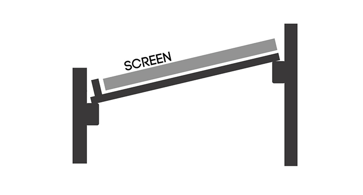
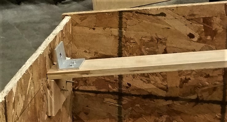
On my original plans, I had two pieces of wood that would transverse the table from its front all the way to its back; it was supposed to have a small locking system that would not allow it to fall due to inclination. A very similar lock system would be used to hold the screen itself.
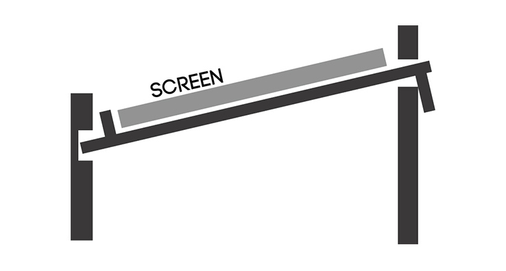
Since I had to remove that piece in order to complete assignment 6, it was time now to redesign a similar structure using the already built table. The thing I came up with turned out to be much simpler:
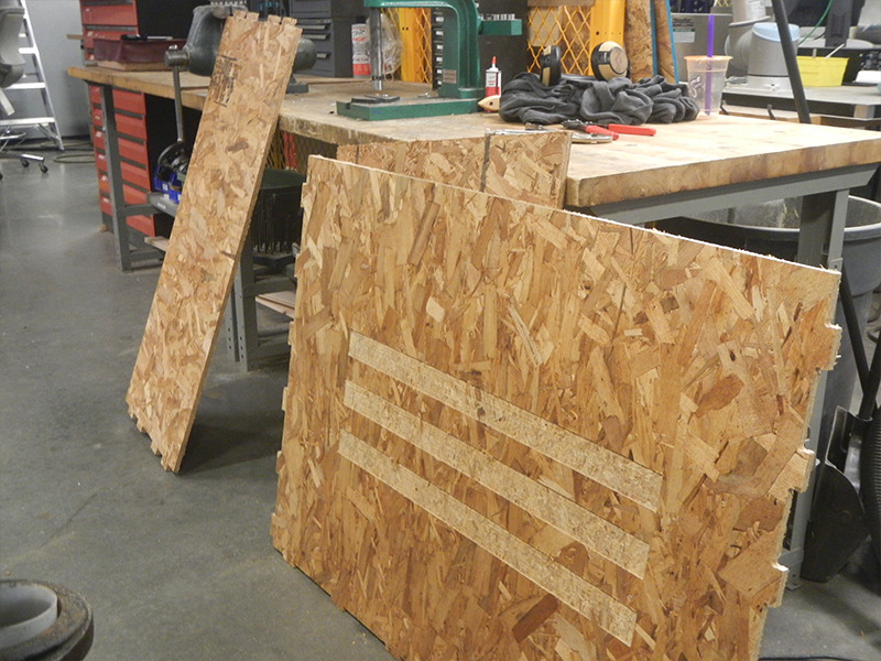
It took me some few measurements [and some search through Media Lab's trash cans] to find the perfect piece of wood to the job; after being oriented by Seth on using cutting tools, I simply cut the woods myself and built the system:
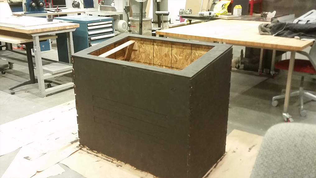
The last piece I had to design was the very top of the table, that would complete the area that was not being covered by the screen. Now considering the other screen size, I simply designed the vector with Illustrator, before using OCB paremeters to vectorize it for the shop bot to cut.
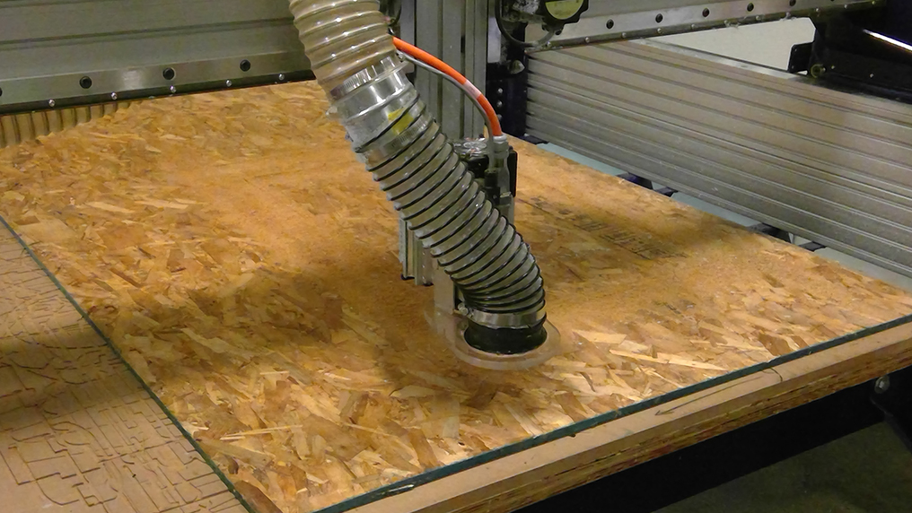
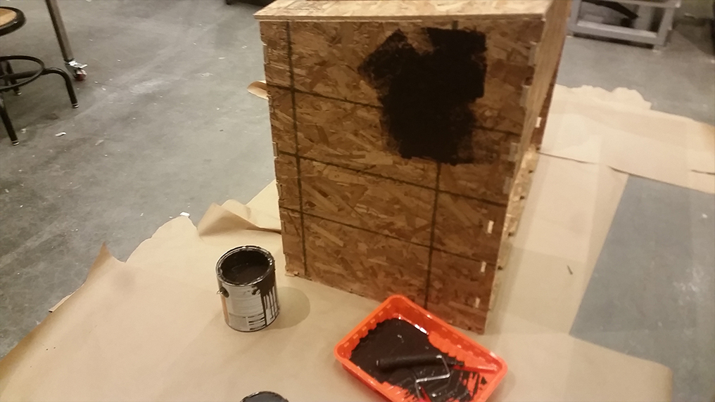
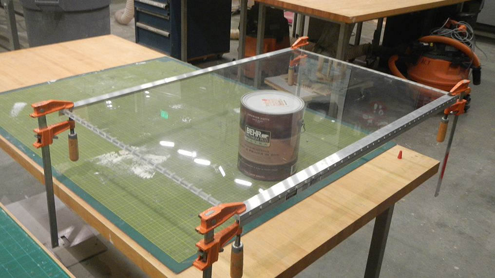
Having the complete structure of the table, it was finally time to paint it.
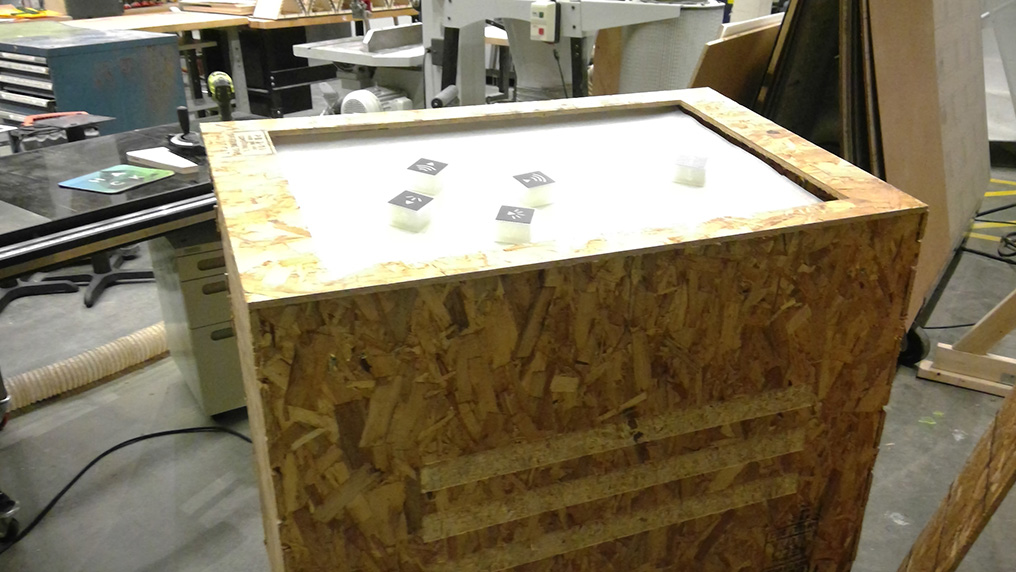
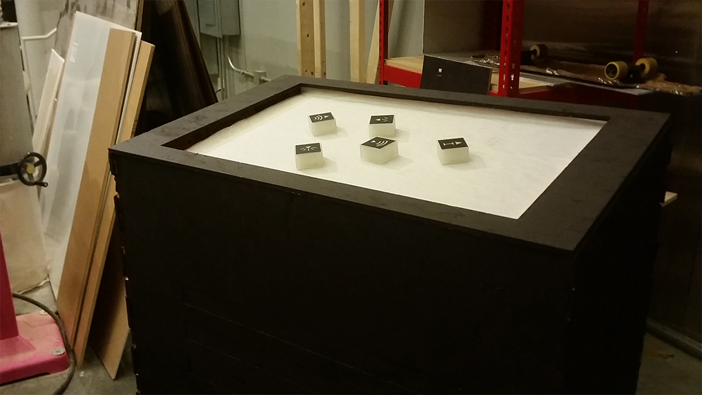
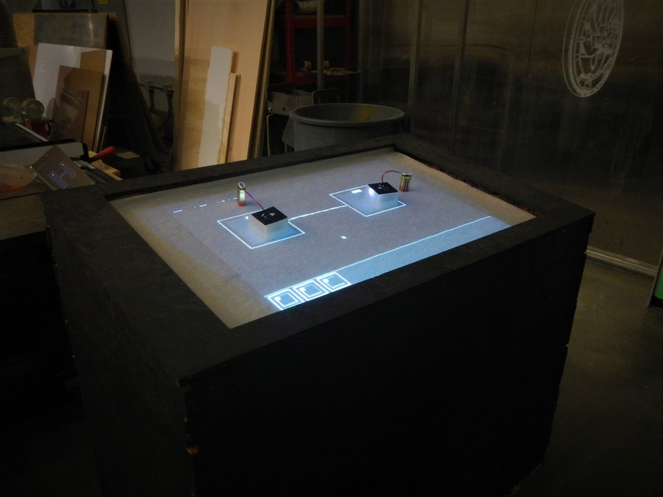
Here's the table final structure with the already-built screen and some of the physical mods over it.
The Touch Screen
Following the Instructables' projects I described above, I had deciced to use Diffused Surface Illumination as a technique of getting the "touch" functionality. This works by having touch being detected by infrared light; we have a simple, white and opaque layer that stands right in front of our user and that is touched. Right underneath this, we have a thick transparent layer (for my case, acrylic), inside which there's a constant flow of infrared light (for this case, I will have dozens of infrared LEDs literally drilled inside the acrylic). When the user touches the first layer, the opaque material touches the transparent one and infrared is immediatly diffused from that spot: the whole system then works by having a infrared-sensitive webcam that detects those spots. Having this system set up, interfacing is then simple: we have a projector at the bottom of our structure that projects the interface on the opaque layer. Appropriate software is then used for callibration and touch-binding.
I planned a small-trip to both Homedepot and Reynolds (it was molding and casting week!) to buy materials for both the assignments and my final project.
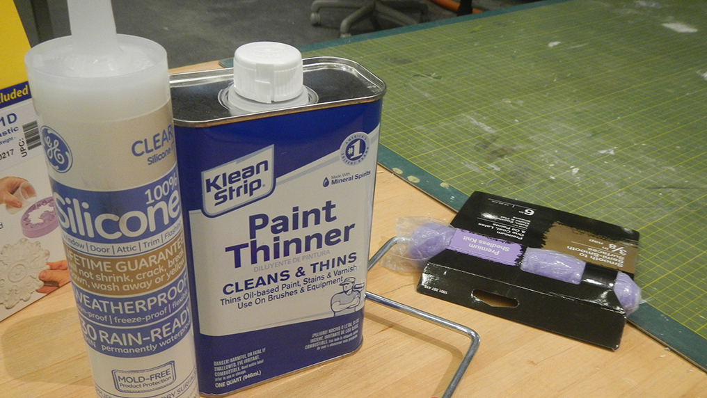
Here's all the stuff I got for the screen:
- Angle Aluminum - Homedepot
- Paint Thinner - Homedepot
- Silicone - Homedepot
- Piece of Acrylic - a group from Media Lab was throwing away a piece that was just perfect for this. (here's also why I changed the screen size :) )
- Drafting Paper - Amazon.com
- Infrared LEDs - Amazon.com
- Resistors - used from the shop
- Wiring - used the shop's vinyl cutter
- Webcam - provided by one the class' TAs
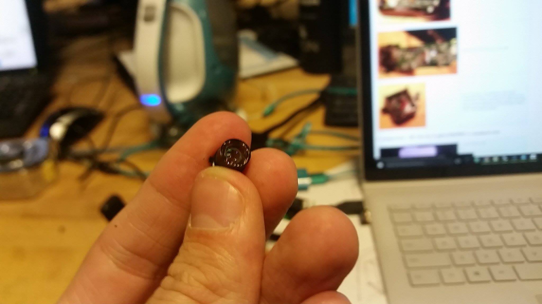
Note that the webcam must be infrared sensitive. Even though most of them are indeed able to respond to infrared, you can maximize it by hacking into it and removing/breaking its infrared lens:
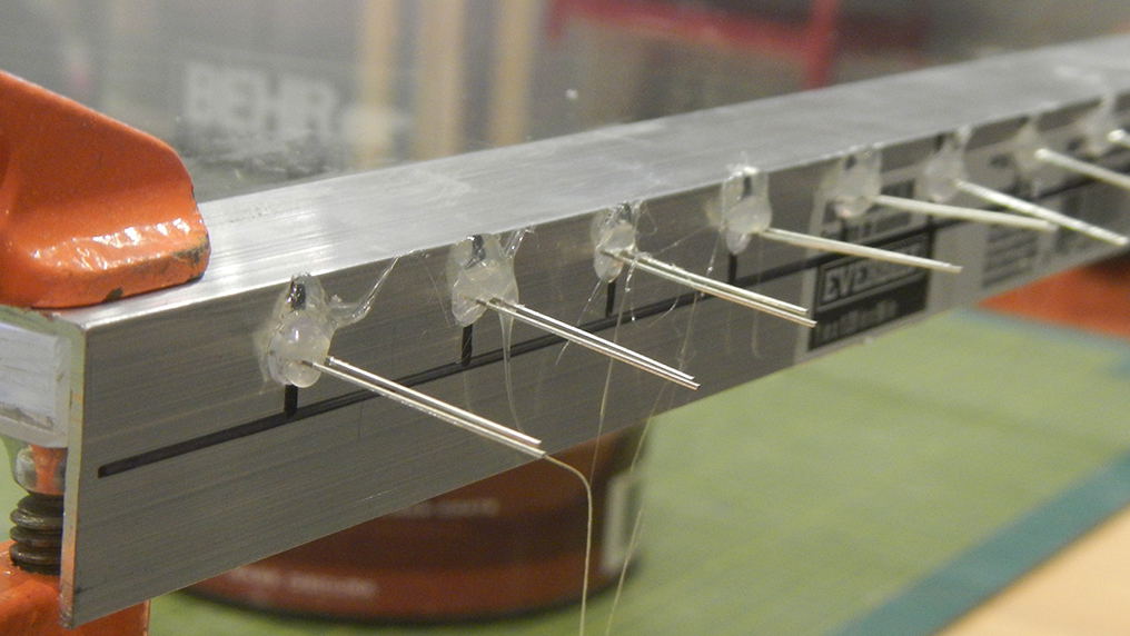
Having all the materials, the first step was to cut and drill the angle aluminum that would hold the Infrared LEDs while helping sustain the table. After measuring the acrylic screen and cutting the aluminum accordingly, I decided that having a gap of one inch between each drill for placing LEDs would most likely be sufficient.
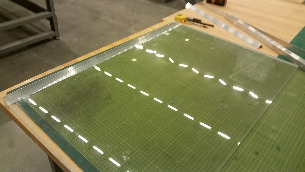
Having finished drilling the aluminum, I then used it as a base to drill into the acrylic. I didn't find a nice way to determine the depth precisely when drilling, so I did it mostly by estimating during the process - as you might have guessed, some of them were far to deep whereas some of them were not deep enough and would require me to re-drill them.
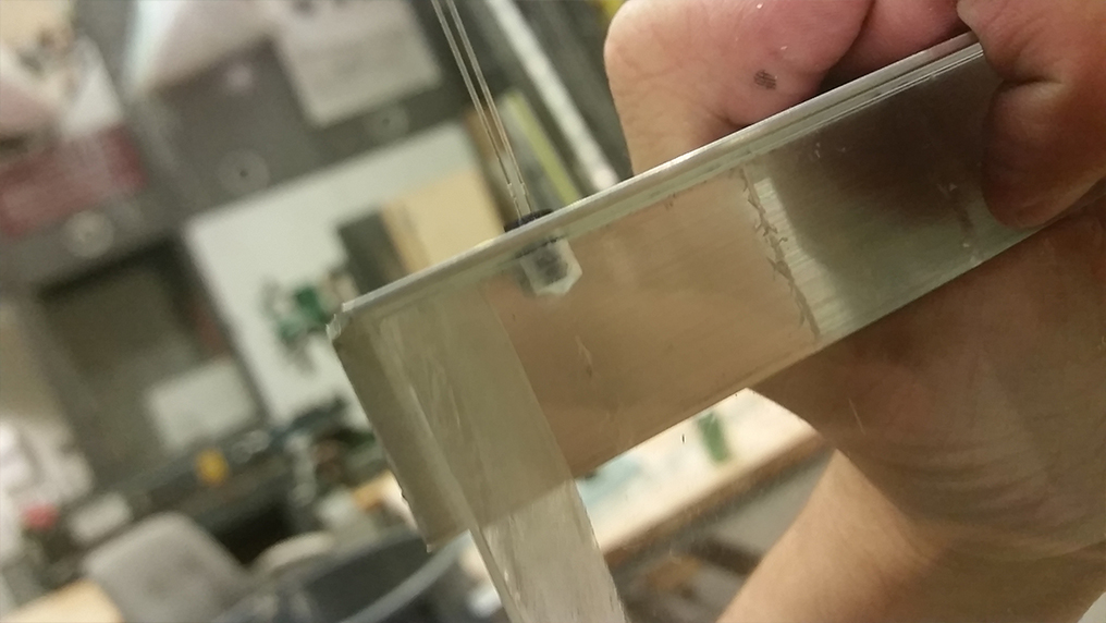
I glued the aluminum and the acrylic with epoxy. I decided not to have aluminum around all of the structure, since in the table design (see above) I just have two holding components to hold the screen.
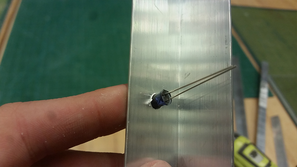
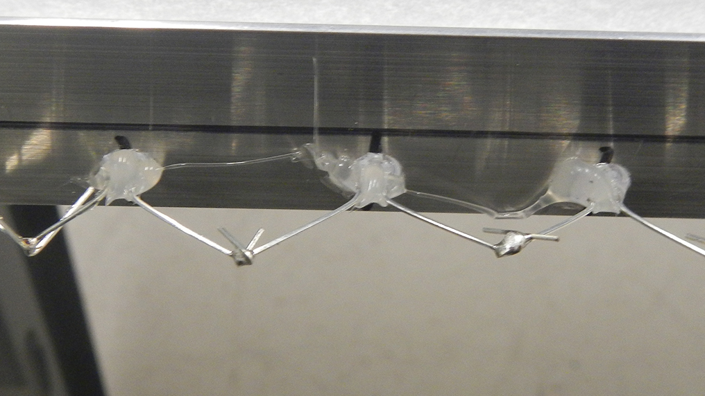
Then, I started placing the Infrared LEDs. A careful way of placing them required being aware of aluminum's conductivity and hence avoiding having the LEDs' wires touching it. Even though most of the LEDs would fit just perfectly in the drilled space, I still added hot glue to them. Note that LEDs' polarities are important and I was especially attentive to this. Using the same approach from Instructables, I decided to power a set all of the 98 LEDs by having sets of 7 LEDs + 10 ohm resistors in parallel.
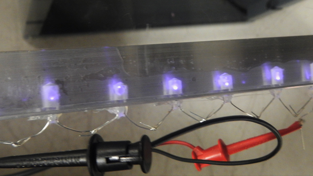
After testing all the sets of LEDs, I then took the whole screen to Media Lab's basement and soldered all of my system. The wiring was possible by using the vinyl cutter. I then hacked a simple power supply and used it to power those copper strips.
Now we can already test our LEDs, using the hacked webcam:
Still not ideal, but in the way to go. Next step: the upper layer.
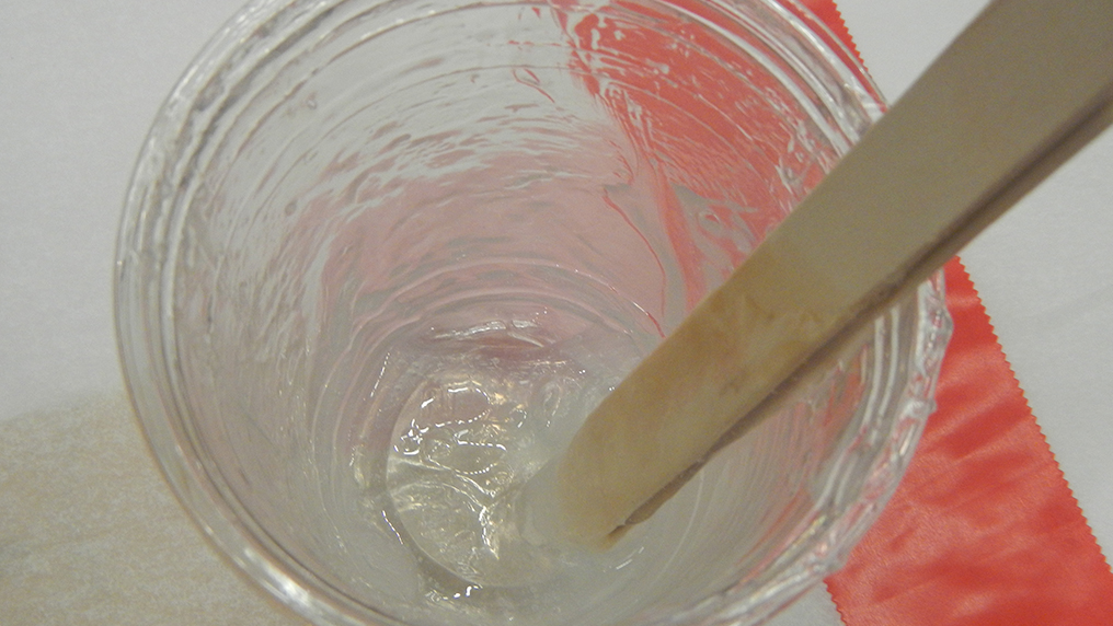
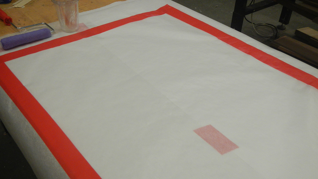
To create it, I used the technique found here which uses paint thinner and silicone. The idea behind this technique is to be able to "melt" the sillicon into an usable paint-like liquid, and one is able to do this by carefully adding the thinner while slowly mixing the silicone till it's at the desired almost-liquid-like form. I then simply applied a mixture of the sillicon with the paint thinner over the drafting paper multiple times (around 4 or 5 times should suffice for our purposes).
Back to the basement, it's time to try the new silicon layer:
Now the final step to have a full touch screen is to process the image data and, finally, bind this data to a computer. One can easily do this with especialized software: I used the open-source interface CCV for detecting the touch - the software requires you to play with some parameters, but this step is all about testing and playing with it until the desired conditions are met.
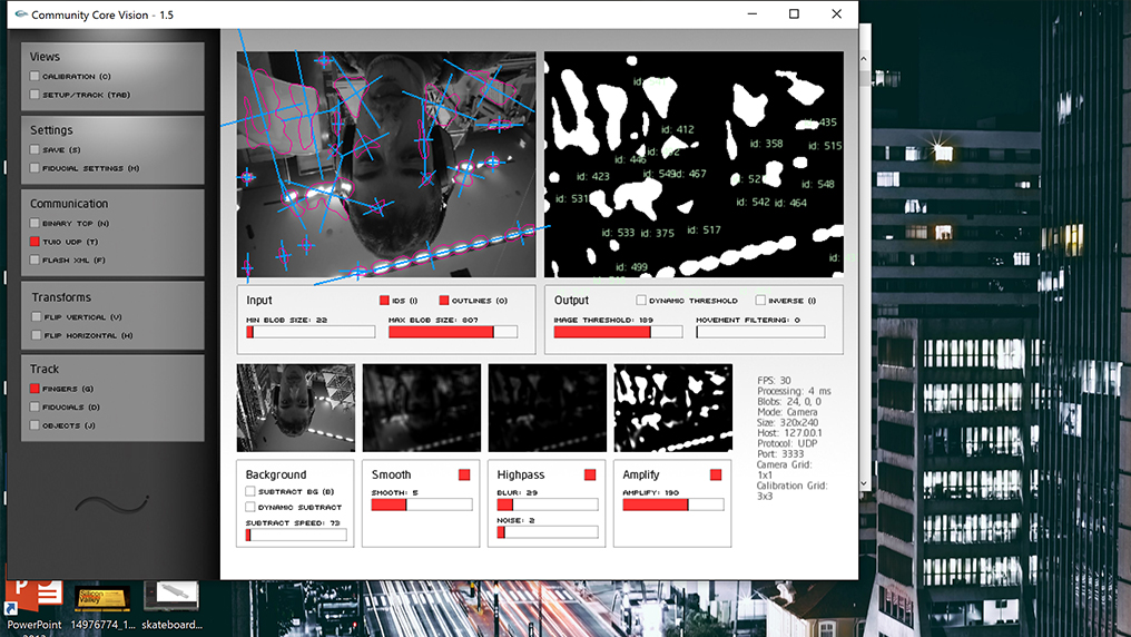
The great advantage of this software is that it is impressively easy to callibrate video data with a reference on a computer screen. This is me using CCV to callibrate the touching pattern with reference on my screen (note that I'm filming with my camera now, and hence the infrared light is not being detected).
Once we've callibrated, we're in good position to bind the touch with our cursor pointer from our computer; I tried multiple different software, but I ended up using the simple, rather intuitive Touch Injector. A single click and, overlaid CCV, Touch Injector allows you to have total binding to the cursor. This is me playing with my own computer by randomly touching on the table
As you can see, callibration turned out to be much painful: visible light would mix with IR light and easily have touch-detection software going crazy.
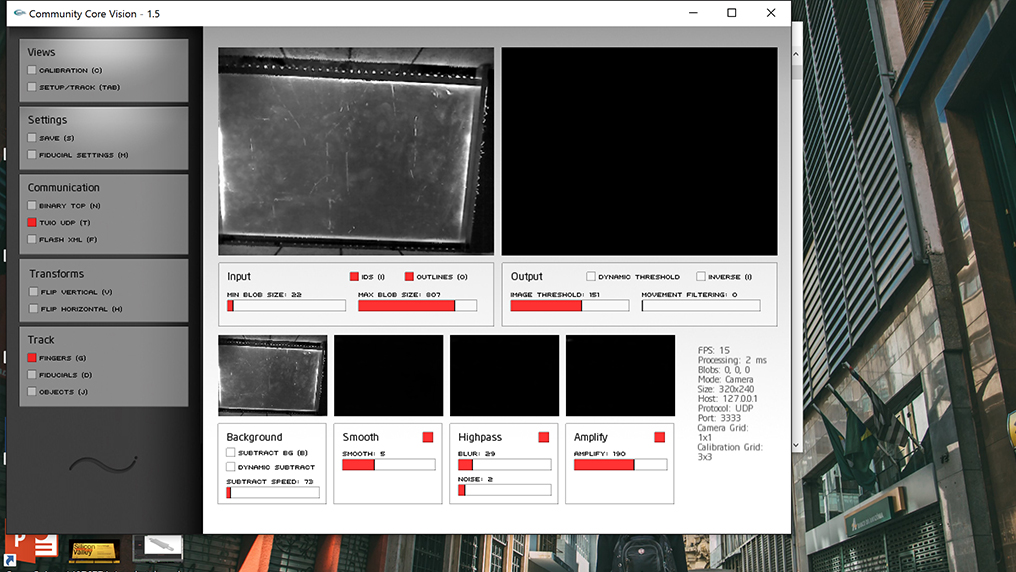
But then a huge, huge step was made by buying an "IR" lens (it's named like this but it filters other frequencies of light!). By blocking all other frequencies, we're now in good position to detect the exact touch and motion of our fingers (even the screen projection is now filtered):
Back to CCV, I readjusted most of the settings to our lens:
And the performance now is exponentially better:
The Mods
If designing the table was hard, designing the pair "digital mod - physical mod" definitively was a complicated task. Although the final minimalist design turned out to be really simple, I spent much time thinking and brainstorming about it. I tried to keep in mind that I wanted to have something that would allow for the digital and the physical to resonate with each other (as I was redesigning the original mods to have them projected at a table and adapted to a touch screen), but still have something that would be intrisically physical and "modular". Trying to keep the "updatable" nature of mods, I also wanted to design something that could easily be opened and altered - as the core of the physical mods is going to be in its circuitry, I would simply have to create a simple system to open them and allow the user to change, add or remove circuits and components; similarly in the case of the digital mods, I would have to have something that could be "closed" (meaning it's multiple components could be compacted into a single screen element), in order for the countless, often not very user-friedly modules to be intuitive and provide a great interface for projection over a screen.
Data binding was also a key design challenge: how should the physical mods communicate to their digital counterparts? I had considered multiple options by then
- QR codes: one could easily detect a given physical mod to the computer by having a webcam detecting it from down the table. This would be possible by having either a QR code pattern illuminated with IR light or by having a 3D shape that, once over the table, would produce the QR pattern. The issue with this was data-binding: it's easy to detect the presence of a module by having this, but it's much more complicated to have data flowing between it and the table.
- Variable QR codes: a way to solve for binding would be to have a variable QR-code in the bottom of the physical mod, in such a way that the pattern that it pro.uces informs the table about itself (which mod it is), the data type (what kind of data it is transfering) and the data value. This would require having a screen or other much more complicated (and expensive) technology for each mod, which would be way too troublesome for a single semester. It also doesn't allow for two-way data binding: the mod would easily transfer information to the table, but the reverse wouldn't easily happen.
- BLE: I've considered using Bluetooth Low Energy throughout most of the project; I was particularly interested in the velocity and the ease with which one can have data binding and flow; moreover, BLE's very structure proposes a centrar, "master" component that commands all of the "slaves" - not different from the relation of the table with the physical mods.
- Wifi: However, the final decision was on using Wifi modules. After testing both BLE and Wifi over the Networking week, I realized having BLE communication through a browser would go beyond the necessary; besides this, having modules being represented either as "webpages" or values at a database started to make much more sense to me. I could then have mods directly reading from this database, while having a ESP8266 module easily POSTing and GETing from it.
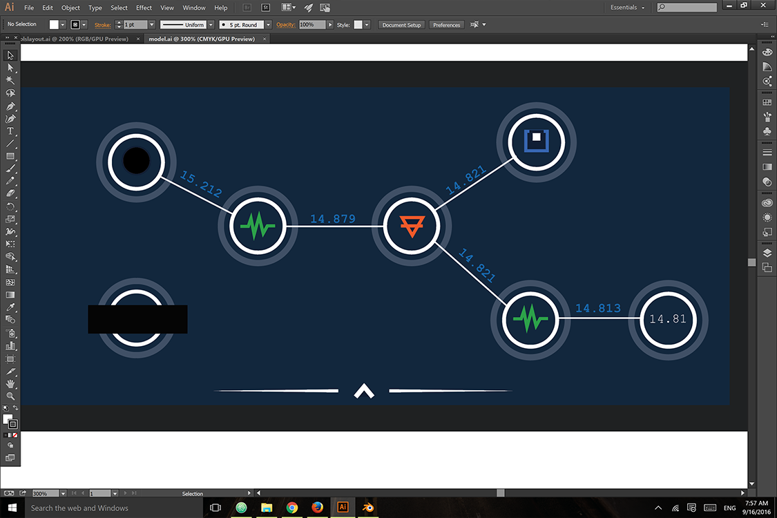
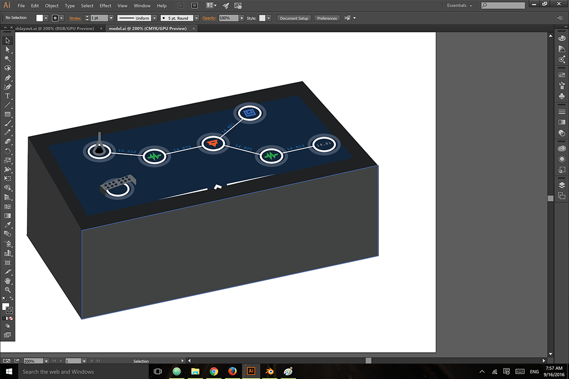
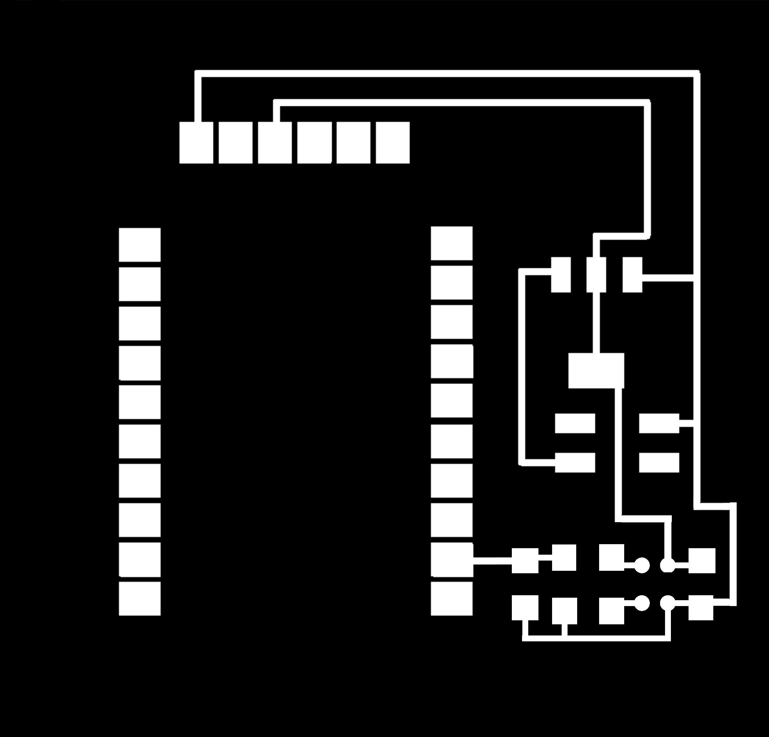
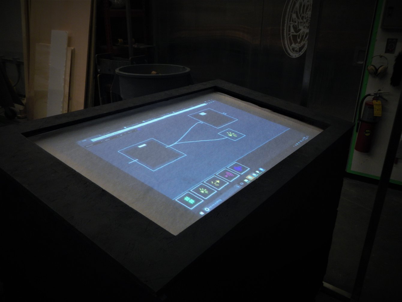
The final result was much more minimalistic than I expected: I decided to standardize the digital mods by having them limited and shaped by squares, as well as having symbols to represent functions for each mod.
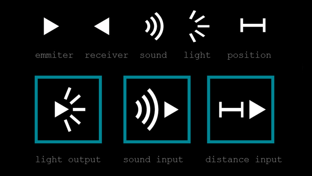
By invoking a given symbol/function on the table (the digital side), I would create an event that would call for and bind to a physical mod of identical symbol (if all of this sounds confusing, jump see the images below to have a better idea of all of this interfacing and designing solution). Hence, the final design would be square-shaped and would contain a symbol for user interaction purposes.
The Digital Mods
A huge part of this was during Week 12, Interfacing.
Designing the digital mods will not only involve designing a touch-screen-driven user-experience, but mostly setting up a website and a simple (so simple that it shouldn't have this name) database.
First, I spent some time exploring mods and reading its .js core. After downloading and playing with it for a while, I started modifying its interface. First thing to consider was minimalism - reducing the size of the modules by setting up a system to get them compacted and add the option to have it in a reduced state.
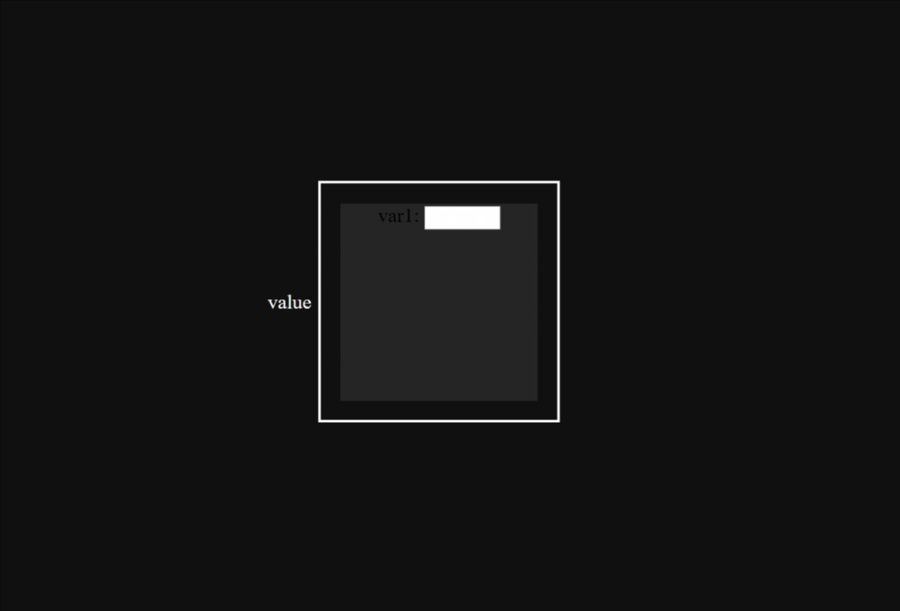
In other words, modules would naturally be small, simple squares represented by a symbol and a title (I've drawn many ideas from the very concept of a GUI); similar to opening a folder, a given mod can be "expanded" and have its parameters, now visible, modified as needed.
This also implies that adding mods and removing them should be as easy as dragging and expanding screen elements: I hence added a small footer that will contain all the mods; an user can add a new mod by dragging it from the menu, and can remove it from the interface by placing it back there; this is the final interface:
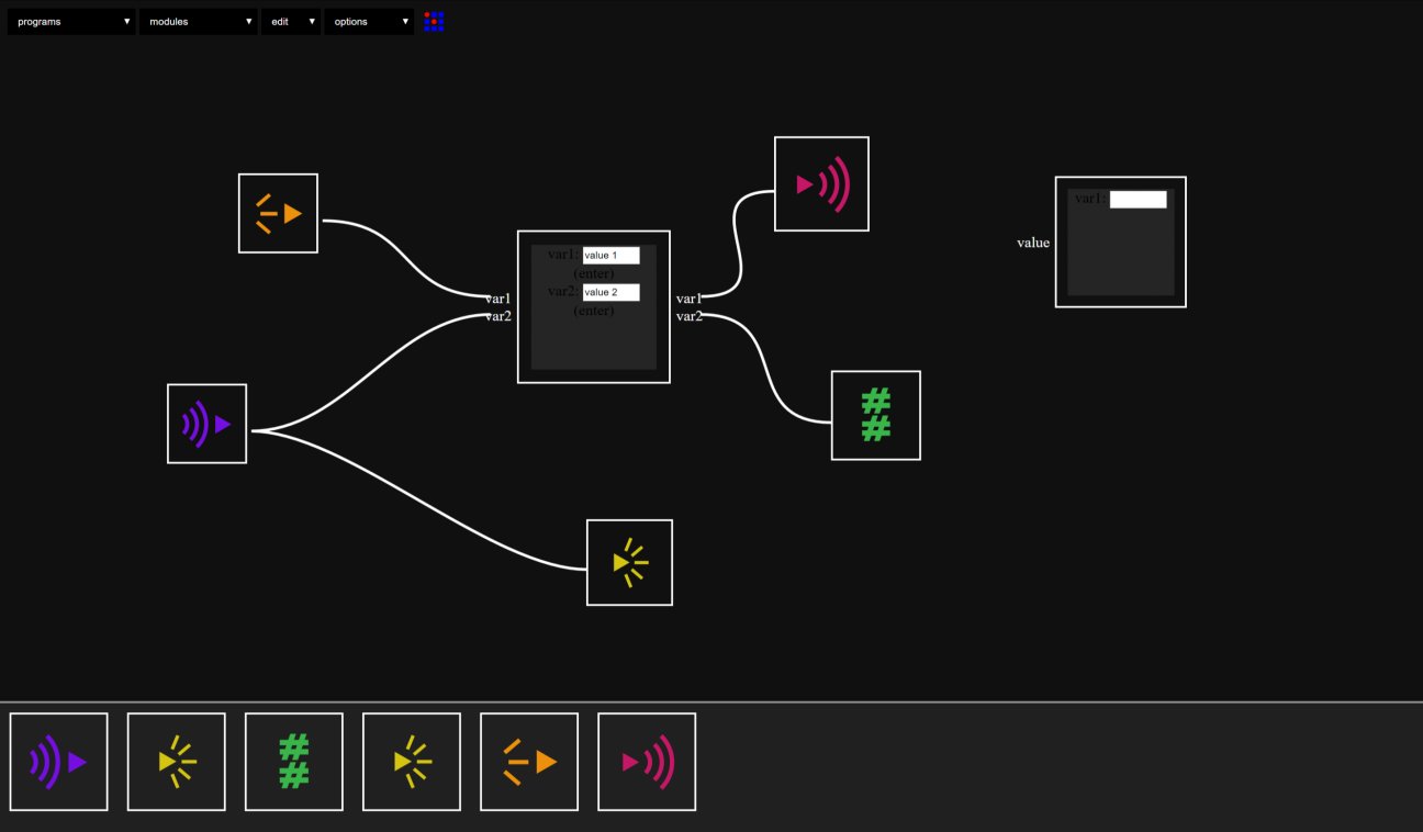
Considering the touch interface, I added event listeners to long-click and double-click - the first activates a function that allows one to move modules around, while the second expands it.
Moving modules:
And linking them:
Now, it's time to stop using the Phant database I used for Networking week and start implementing a much faster software to handle HTTP requests before deploying my website.
To handle requests, I'll be using a simple script of Python by using the micro-framework Flask: I'll set up a simple web app that will be controlled by my Python code, and that will respond according to predefined requests.
To keep track of data, I'll have a very simple .csv file that will be modified according to requests; the first column refers to the module, whereas the second refers to the value it has at that given time. I used prefixes 's' for 'sound' and 'l' for 'light'. This is the csv:
  semmit,8
  lrecei,2
  srecei,2
  lemmit,2
Now I just need to set up my requests: "/" shall return the mods page (in this case, index.html); "/input" will require two arguments (mod and value), and will modify a given mod's value if such module exists; "/output" gets one argument (mod), and will return the current value of that mod if it is in the database; finally, "/database" will return the whole .csv file (for debugging purposes).
  import os
  from flask import Flask, render_template, request, redirect, url_for
  app = Flask(__name__)

  @app.route('/')
  def home():
      return render_template('index.html')

  @app.route("/input")
  def input():
      mod = request.args['mod']
      value = request.args['value']
      s =  ",".join([mod, value]) + "\n"
      fd = open("data.csv", "r")
      lines = fd.readlines()
      fd.close()
      fd = open("data.csv", "w")
      mod_found = False
      for line in lines:
          if line[0:6] == mod:
              mod_found = True
      if mod_found:
          fd.write(s)
      for line in lines:
          if line[0:6] != mod:
              fd.write(line)
      return "done!"

  @app.route("/output")
  def output():
      mod = request.args['mod']
      open_read = open("data.csv",'r')
      page =''
      i = 5
      while i > 0:
          i = i - 1
          read_data = open_read.readline()
          if read_data[0:6] == mod:
              value = read_data[7:]
              return "mod" + value
      return "Not found!"

  @app.route("/database")
  def database():
      fd = open("data.csv", "r")
      lines = fd.readlines()
      string = ""
      for line in lines:
          string += line
      return string


  if __name__ == '__main__':
      app.run(debug=True)
After setting up protocols and requirements, I then deployed my website through Heroku, naming it PhysMods. Feel free to test all of the previously described requests.
Now that we have our data communication lines set up, we can modify mods to handle communication. Drawing from Neil's mods, I created simple modules that will either change data or read data through HTTP requests (note that most of the processing of the data is done through Python, so that our JavaScript is not required to process much of our request responses). This is a simple light emmiter module: it has a single input parameter that, once received, is posted into our .csv file.
  (function(){
  var mod = {}
  // name
  var name = 'lightemitter'
  // initialization
  var init = function() {
    mod.value = 0;
    mod.emitter = 1;
   }
  // inputs
  var inputs = {
    value: {type:"integer",
    event: function(evt){
       mod.value = evt.detail
       post_value(mod.value)
     }
   }

  }
  // outputs
  var outputs = {
    }
  // interface
  var interface = function(div){
    // change parameters buttons
    mod.div = div
    // change mod number
    div.appendChild(document.createTextNode('var1: '))
    input = document.createElement('input')
       input.type = 'text'
       input.size = 6
       div.appendChild(input)
       mod.emitter = input.value
  }
  //Local Functions
  function post_value(value) {
      var root = "https://physmods.herokuapp.com/input?"
      var emitter = "lemmit";
      var webpage = root + "&mod=" + emitter + "&value=" + value;
      var request = jsonp(webpage, 'callback', function(json){});
  }
  function jsonp(url, key, callback) {
      var appendParam = function(url, key, param){
              return url
                  + (url.indexOf("?") > 0 ? "&" : "?")
                  + key + "=" + param;
          },
          createScript = function(url, callback){
              var doc = document,
                  head = doc.head,
                  script = doc.createElement("script");
              script
              .setAttribute("src", url);
              head
              .appendChild(script);

              callback(function(){
                  setTimeout(function(){
                      head
                      .removeChild(script);
                  }, 0);
              });
          },
          q =
              "q" + Math.round(Math.random() * Date.now());
      createScript(
          appendParam(url, key, q), function(remove){
              window[q] =
                  function(json){
                      window[q] = undefined;
                      remove();
                      callback(json);
                  };
          });
  }
  return ({
     name:name,
     init:init,
     inputs:inputs,
     outputs:outputs,
     interface:interface
     })
  }())
Note the jsonp local function - in this case, we are not expecting any response, but we are still using it to "GET" and change parameters at the .csv file. I have also added a "mod number" parameter considering that more than one mod might have the same function and hence must have an unique id. However, for this project, we won't need to bother with this.
The code for the light receiver follows a very similar pattern, except that now we are outputting and constantly listening for values at our database:
  (function(){
  // module globals
  var mod = {}
  // name
  var name = 'lightreceiver'
  // initialization
  var init = function() {
    mod.value = 0;
    mod.receiver = 1;
   }
  // inputs
  var inputs = {}
  // outputs
  var outputs = {
    value: {type:"integer",
      event: function(evt){
         mods.output(mod, 'value', mod.value)
     }
   }
  }
  // interface
  var interface = function(div){
    // change parameters buttons
    mod.div = div
    // change mod number
    div.appendChild(document.createTextNode('var1: '))
    input = document.createElement('input')
       input.type = 'text'
       input.size = 6
       div.appendChild(input)
       mod.receiver = input.value
     var request = window.setInterval(function(){
        var data = new XMLHttpRequest();
        data.open("GET", "/output?mod=lrecei", false);
        data.send(null);
        if(data.status == 200)
           mod.value = data.responseText.substring(3);
           outputs.value.event();
   }, 400);

  }
  return ({
     name:name,
     init:init,
     inputs:inputs,
     outputs:outputs,
     interface:interface
     })
  }())
The Physical Mods
This section of the final project was also part of a weekly assignment: for more details, see Week 8
Following the design rules described above, I created the physical mods on rhino to resonate with the square-shaped, minimalistic and modular digital mods:
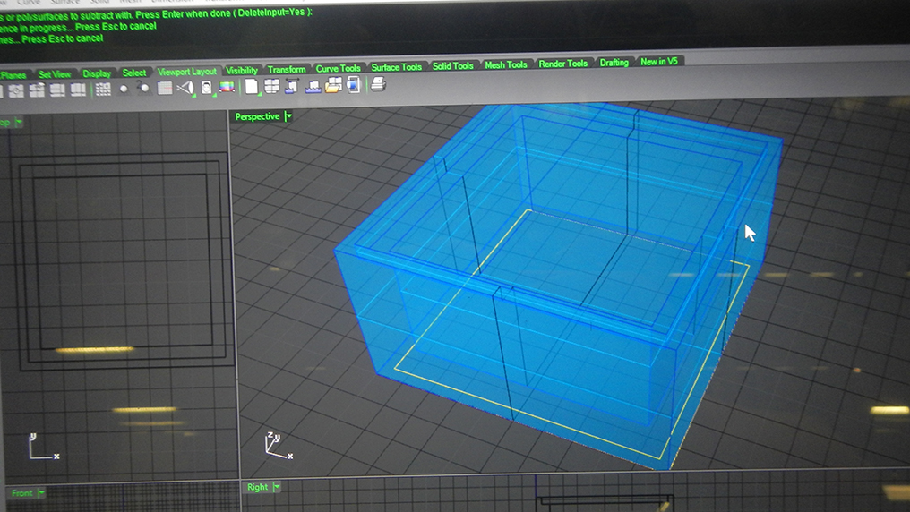
Having the rhino file, I was ready to build the mod (and that week's molding assignment) by milling it out of wax. Even though it was my third time milling out of wax, and even if I was indeed following all the parameters for milling wax, that single mod ended up breaking two end mills: most likely, the thickness of the box was small enough for wax to accumulate inside it when milling was happening; eventually the accumulation was such that the end mill couldn't force through it anymore. After breaking the first one, I called for one of the class' TAs and, after re-adjusting all the parameters and changing the end mill, I restarted the project just to discover another broken end mill 15 minutes later.
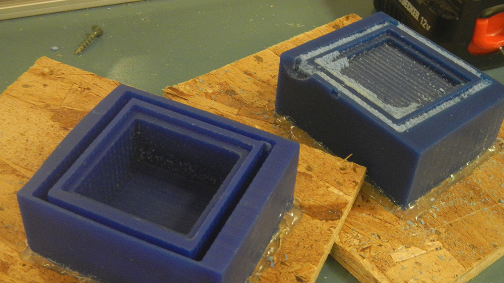
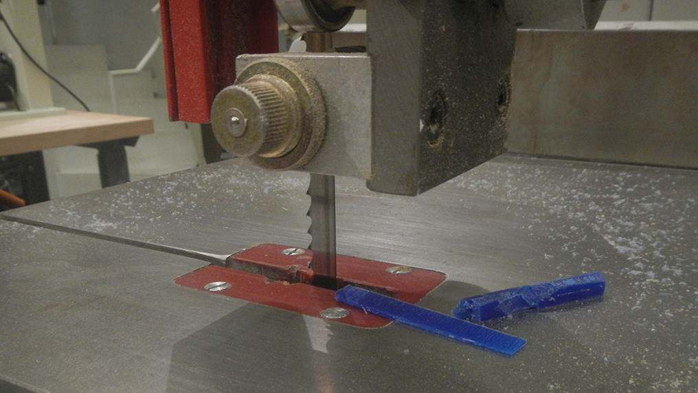
The last trial, however, had been milled to such a degree that I could break it's fundamental piece out of the wax. Having an almost-finished piece, I was able to manually finish the job. Again after Seths' orientation, I used cutting and smoothing tools to wrap up the mold's mold.
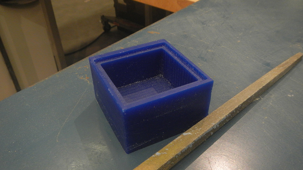
Then, molding simply required me to get a simple paper box to serve as a base on which I emerged the mod box; after curing the Oomoo, here's the result I got:
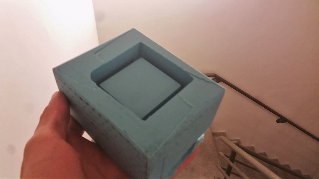
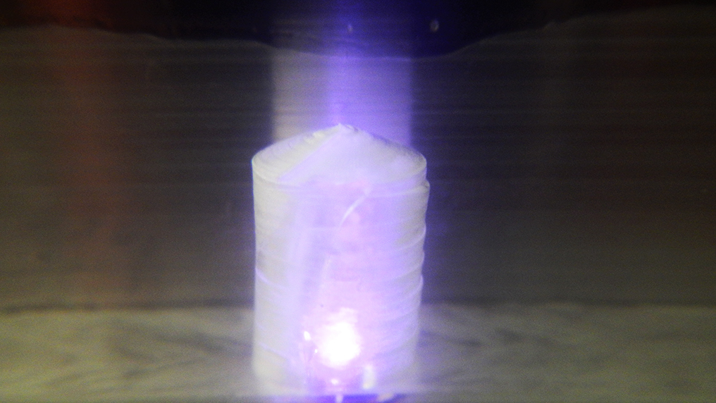
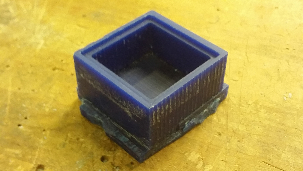
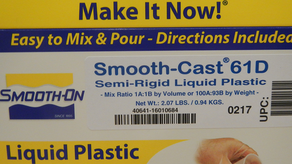
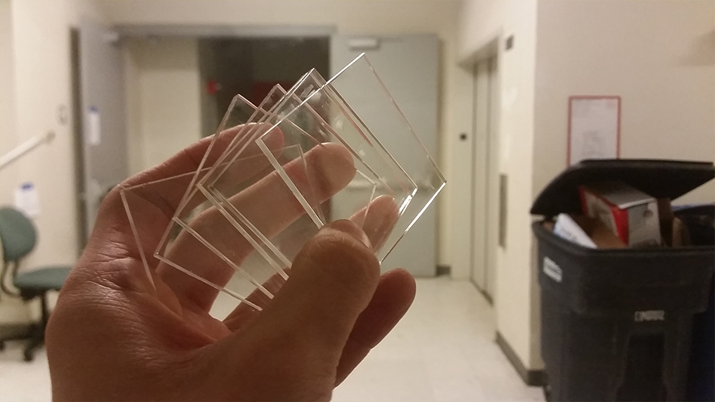
Finally, the material I had decided to use was to be somewhat opaque but still able to be illuminated from inside; hence, I chose Smooth-Cast 61D during the field-trip to Reynolds.
Here's how it looks like after curing:
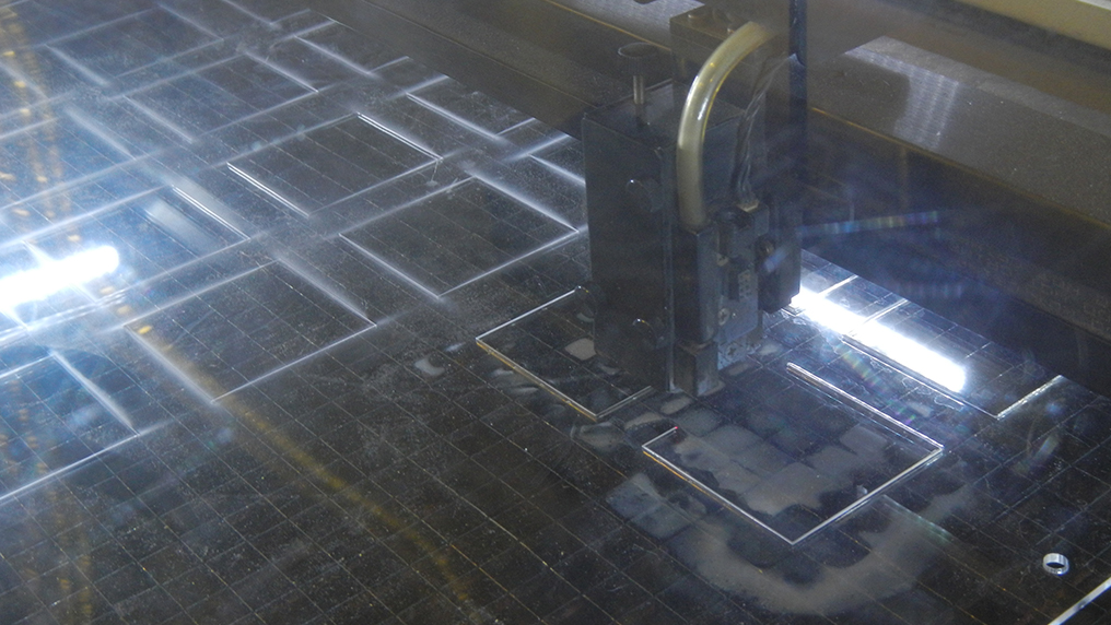
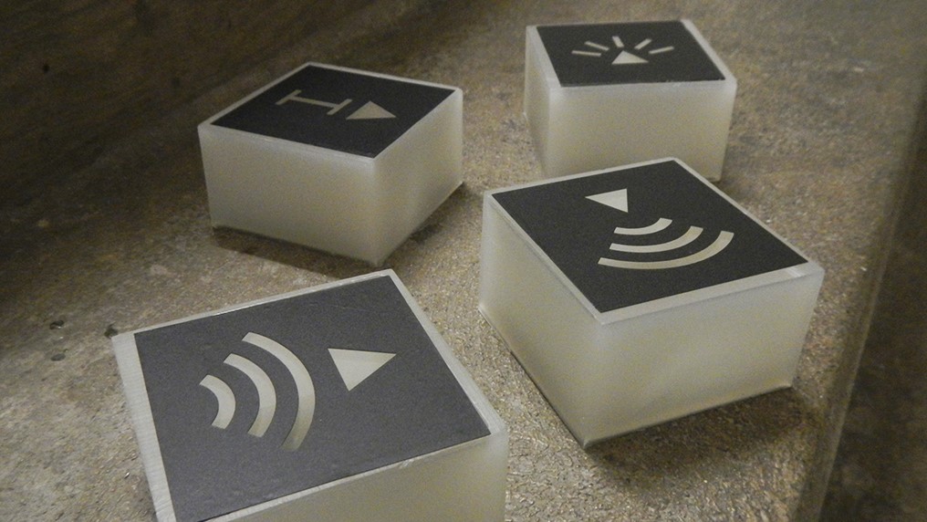
To build a small box cap for the mod boxes, I precisely laser-cut squares out of acrylic:
Finally, the symbols were cut out using the vinyl cutter on black vinyl; here are the final pieces:
Now we can finally start building the electronic components that will compose our modules.
Following the digital, squared pattern, I tried to keep most of the circuitry and components organized in a square and compact space.
Fortunately, I had much time during Networking and Interfacing weeks to play with both BLE and Wifi, and I had very soon decided to use Wifi to power connection on my mods (by having a cloud database for the table). In order to accomplish this, I'll be using one of Adafruit's Huzzah boards (virtually, an ESP8266) per physical module, basically having an IoT node per mod.
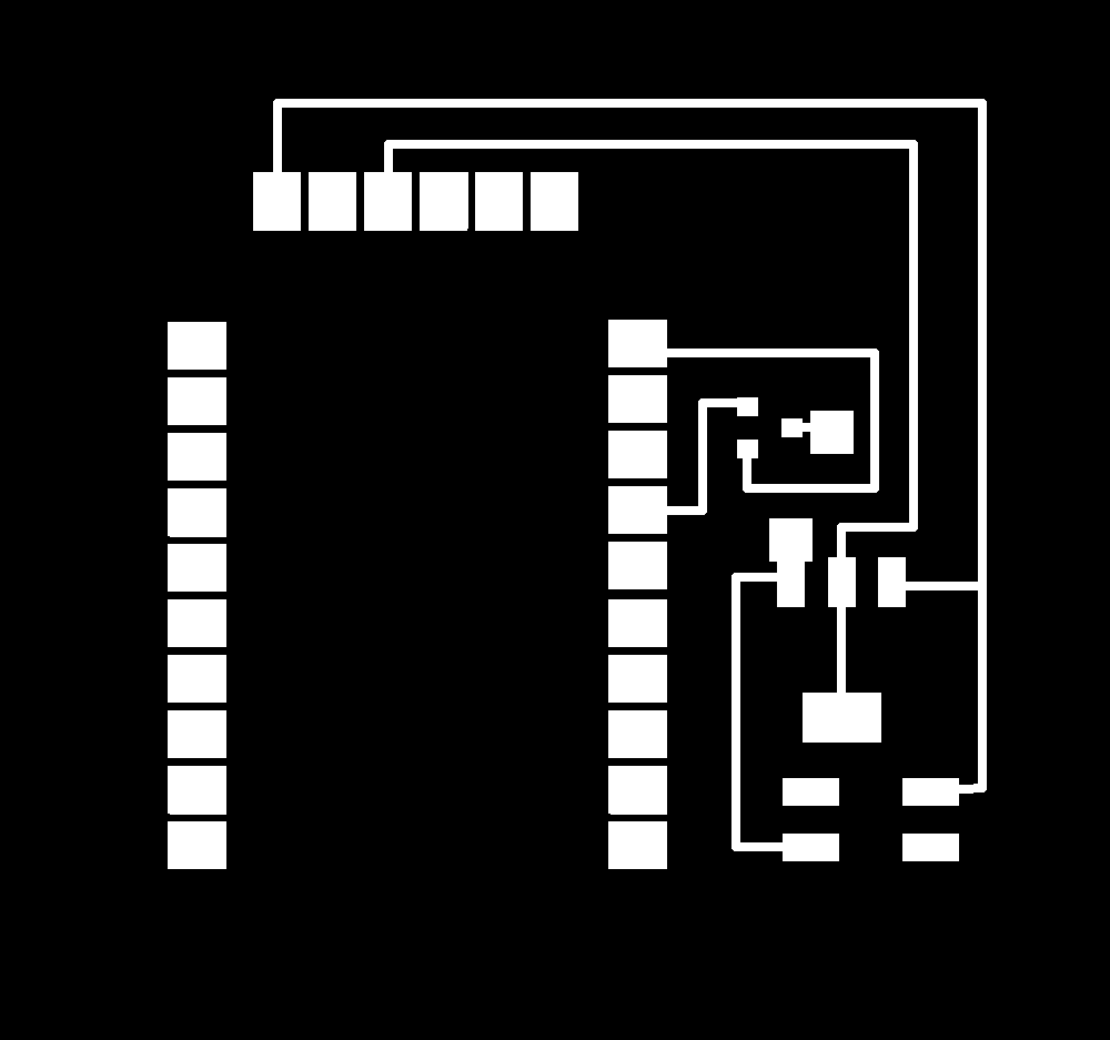
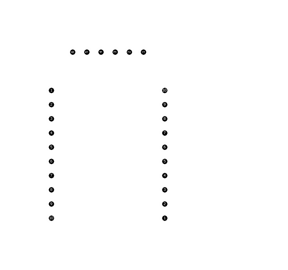
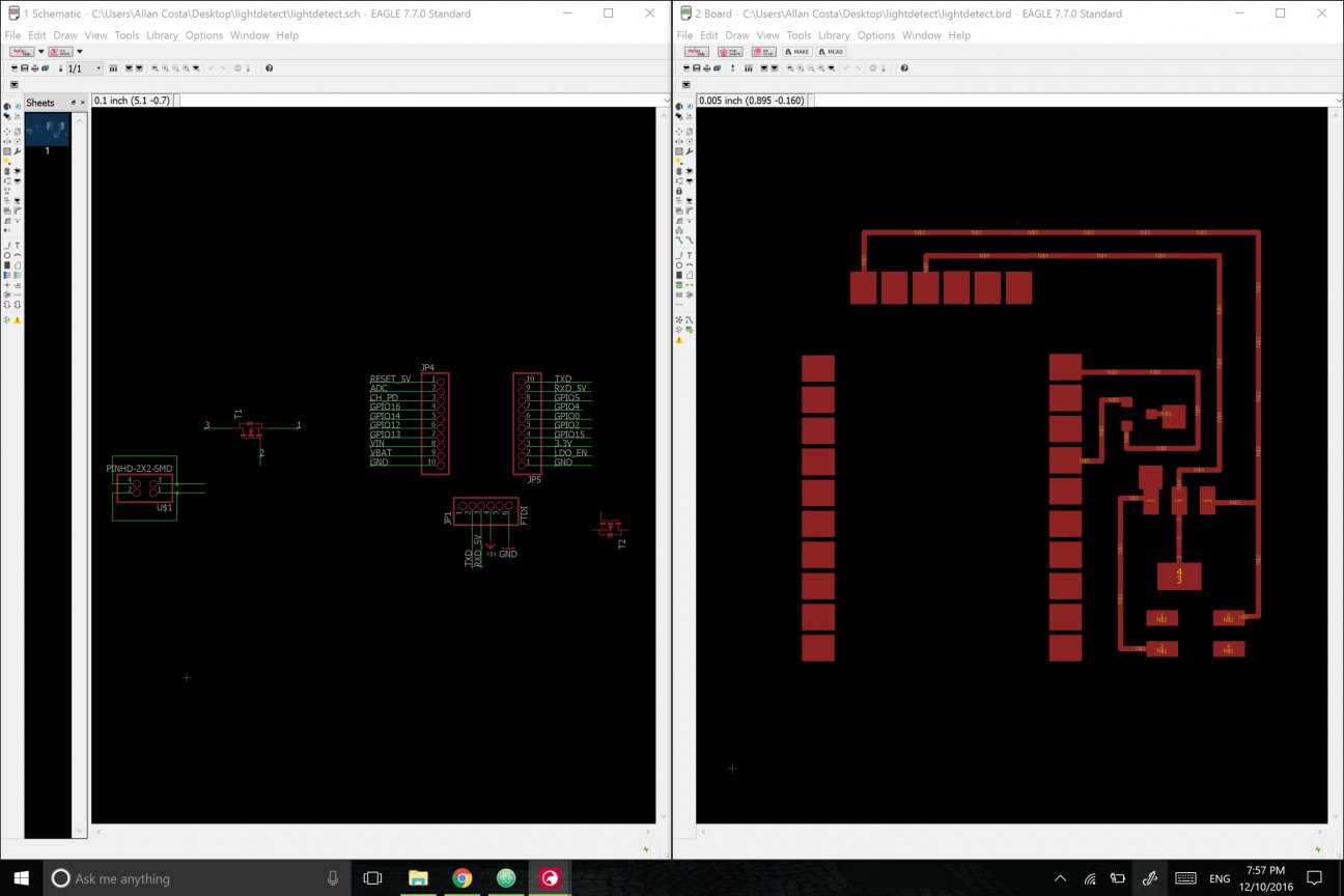
The first - maybe simplest - circuit to create was for the light-emmiter mod. Still drawing from Networking week, I updated much of the speaker board to have a mini-LED (it's actually huge) to full power. I designed the board to have vias such that Huzzah can be soldered into it, while still programmable with the FTDI cable.
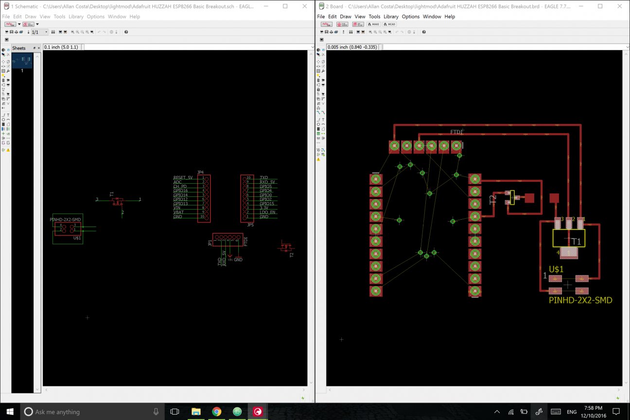
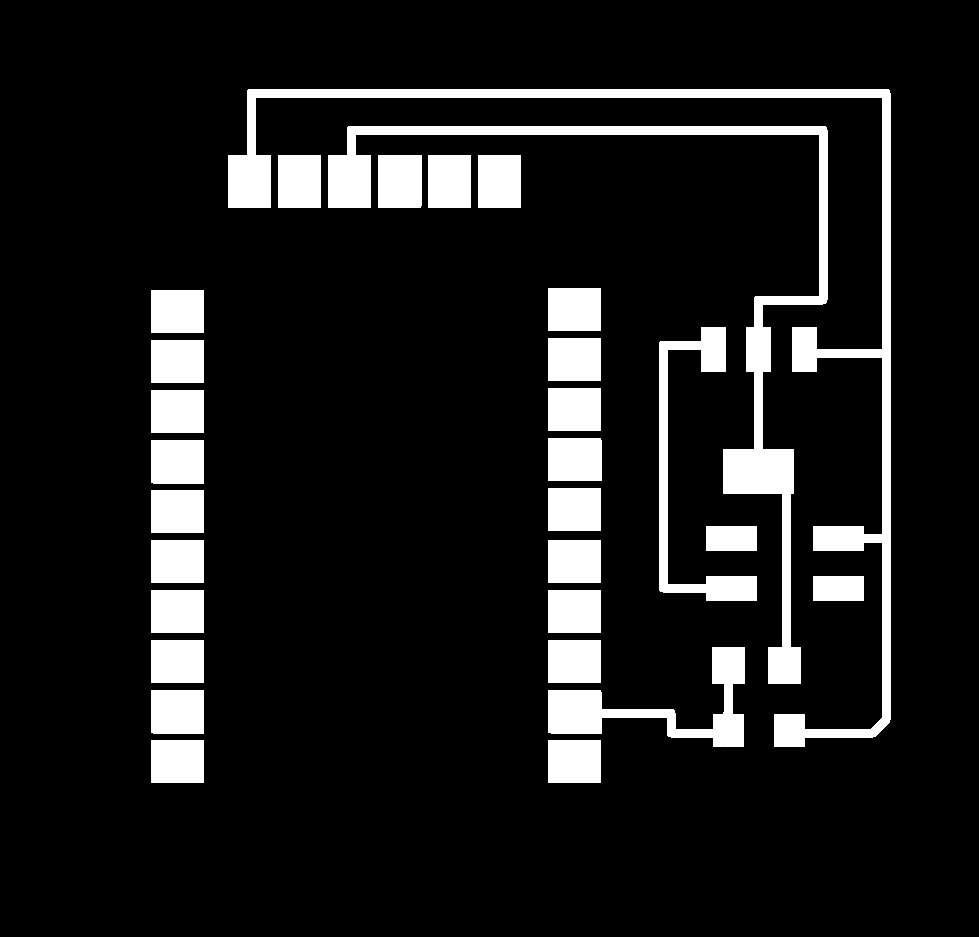
Here are the .png files for the light-emmiter mod

Although I had used much of pure C code for BLE, in the case of Wi-Fi it's still much easy to have Arduino (or Lua) uploading directly to our ESP8266 through an FTDI cable. The code here is straightfoward: I'm using HTTP requests to GET data from my server (see the setting up of Digital Mods above!), which already has most of it being processed with Python before being sent (note that we're usign the /output function defined above using Flask). I then just search for the actual value (there's an indicator string "mod" right by its side) and then analogWrite() it to my LED pin.
 include < ESP8266WiFi.h >
 const char* ssid     = "MIT GUEST";
 const char* password = "";
 const int led = 13;
 const char* host = "physmods.herokuapp.com";
 #define DEBUG true
 void setup() {
   pinMode(led, OUTPUT);
   WiFi.begin(ssid, password);
   while (WiFi.status() != WL_CONNECTED) {
     delay(40);
     }
 }
 int value = 0;
 void loop() {
   delay(50);
   WiFiClient client;
   const int httpPort = 80;
   if (!client.connect(host, httpPort)) {
     return;
   }
   String url = "/output?mod=lemmit";
   client.print(String("GET ") + url + " HTTP/1.1\r\n" +
                "Host: " + host + "\r\n" +
                "Connection: close\r\n\r\n");
   delay(50);
   while(client.available()){
     String line = client.readStringUntil('\r');
     if (line.substring(1,4) == "mod") {
       line = line.substring(4);
       int analog = line.toInt();
       analogWrite(13, analog);
     }
   }
 }
This is the final light emitter circuit:
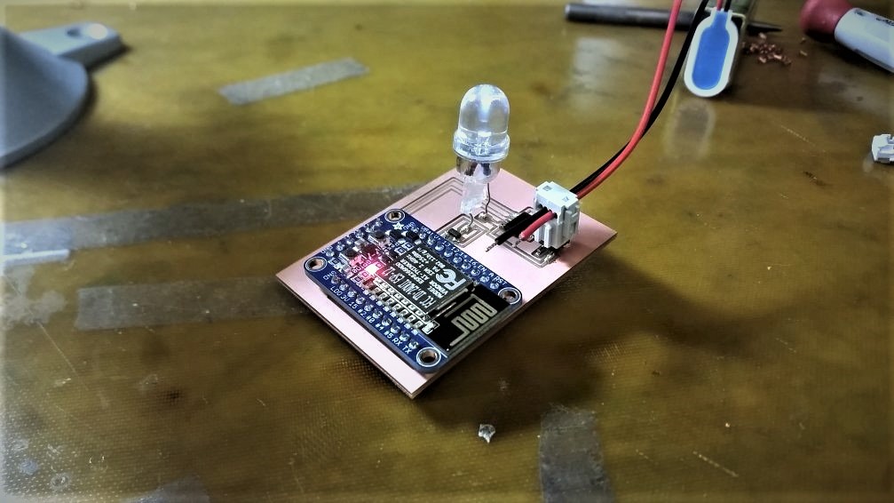
After programming the mod, we can already start testing it. In this video, I have a variables mod inputting to our light emmiter mod:
Now we're in good position to focus on the light-emmiter's brother, the light-receiver. Compared to the emitter, an light-receiver turns out to be even simpler: a photoresistor + an analog read pin and we're good to go.
Here, I'm regulating the voltage before having a simple voltage divider with a 100MOhm resistor and our "sensor". Note that our resistance is different from Neil's original board on Input week, for our Huzzah analog pins expect voltages between 0 and 1.
Here are the png files:


The code is not much more complex either: this time, we're simply analogRead[ing]() our light sensor's voltage value before GETting a request using the /input? function we created - again, we're handling most of the job to python.
    #include < ESP8266WiFi.h >
    const char* ssid     = "MIT GUEST";
    const char* password = "";
    const char* host = "physmods.herokuapp.com";
    #define DEBUG true

    void setup() {
      pinMode(A0,INPUT);
      WiFi.begin(ssid, password);
      while (WiFi.status() != WL_CONNECTED) {
        delay(460);
      }
    }

    int value = 0;
    void loop() {
      delay(50);
      WiFiClient client;
      const int httpPort = 80;
      if (!client.connect(host, httpPort)) {
        return;
      }
      value = analogRead(A0);
      String url = "/input?mod=lrecei&value=" + String(value);
      client.print(String("GET ") + url + " HTTP/1.1\r\n" +
                   "Host: " + host + "\r\n" +
                   "Connection: close\r\n\r\n");
      delay(50);
      while(client.available()){
        String line = client.readStringUntil('\r');
      }
    }
And here is the pair light-receive and light-emmit modules:
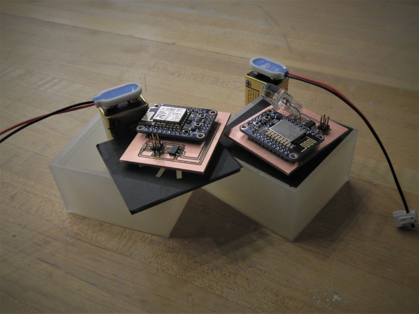
Now that we have the two modules built and programmed, the website deployed and the new modules built, we can finally test the whole integrated system; here, I've linked the light receiver mod with the light emmiter mod; then I just turn on a flashlight to the linkage happening:
Although data binding ended up working perfectly, the timing was not what I expected: each get request for both changing values and getting values was much longer than I planned - most of the requests were taking some hundreds of milliseconds, a considerably small amount if we are to use lighting systems Ilike our two modules) but definitively not enough for musical systems.
Now regarding the sound modules, it's worth noting that the circuit is the exact same for the light emitter module: instead of a "mini-LED", we have a speaker! The sound-receiver is somewhat trickier, but ultimately similar too:
And I've kept the same size for the light receive module:
The code for both of them are equivalent; the only difference is that, instead of using l = light, we're pulling from and pushing to s = sound. So our emitter is requesting from /output?mod=semitter and our receiver is pushing to /input?mod=sreceiver.
Integrating
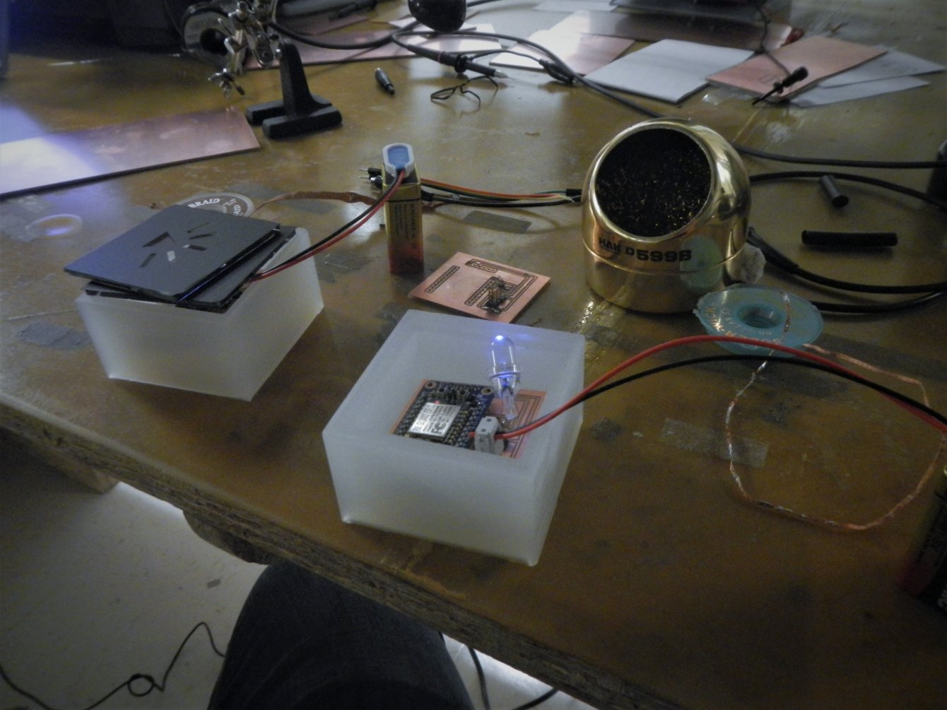
After a whole month of digital fabrication, tons of milled PCBs and countless git pushs, I can finally merge a whole set of maker skills into a final project:
Ha, the version above is the sketchy one! Due to a battery problem, the actual final version was more like:
Still fancy though! :)
Multiple issues emerged on the way, and are still to be solved:
- Batteries: I expected to use small battery packs for the modules, and had design the small boxes based on those; although first trials of testing worked perfectly, the 3-stacked-coin batteries would stop powering my circuits after just some couple minutes. I ended up using the much bigger 9V batteries that, to a fairly good degree, messed up the design.
- Tracking and Positioning: the very reason of having a whole table to the modules was to have them being activated if (and only if) they were to be on/over the table. Although I had a general idea of how to this (an easy solution would be to have another webcam, this time checking for visible light, that expects patterns or colors as inputs) I couldn't find anything that could fit in the scope and timing of the class. Creating a tracking system for digital modules to follow positioning of the physical modules in the screen would require some days of JS development that also ended up being beyond the scope for the final (if you are interested in this, I played a bit with Processing on tracking colors and editing video files; given enough time, I would also have studied a bit of this library, Tracking.JS, that seems somewhat promising for developing such a system). For I had already tested, played and callibrated (and mouse-binded) the touch screen with CCV and Touch Injector, I decided to keep using the system and gave up on this spyral of the project, for now. Still, not necessarily a bad thing, not having the tracker functions means that modules can be anywhere and still be regulated by the table.
- Data Flow: I ended up investing much project time on WiFi and HTTP requests without realizing this could take me to a slow data flow - both inputting and outputting data requires get requests that, even if controlled by kind-of-fast Python code that I wrote myself, are slow enough for the flow of information to lag in order of hundreds of milliseconds. I'll keep playing with the boards and the python app and see if I can get something more optimal. A major step in speeding up the system happened when I splitted the .csv database file in multiple versions - one per module - such that multiple get requests from differente modules can be driven at the same time. Another key improvement was keeping the .csv files at the same root directory of the app and accessing it straight from the code (still using an HTTP request, but not having it requesting through python but rather getting the file itself). Even though the current state of the system is indeed pretty fast, the next improvement step would require improving Huzzah's web requests, which involves a bit more of complexity. Currently, data flow is taking around 300ms.
- (Web)Application: a final step for having the complete system would be to have the whole software migrated to the web. Currently, although I have a Python/Flask app that manages both the modified mods.js and the database, most of the touch screen processing still runs on my computer, out of the web. Hence, a further essential step would be to migrate to JavaScript the software for processing webcam image and detecting touch; this also applies to building the system for tracking modules and positioning the interface according to physical modules' positions.
Nevertheless, the overall structure works quite well, and the project ended up being a success.
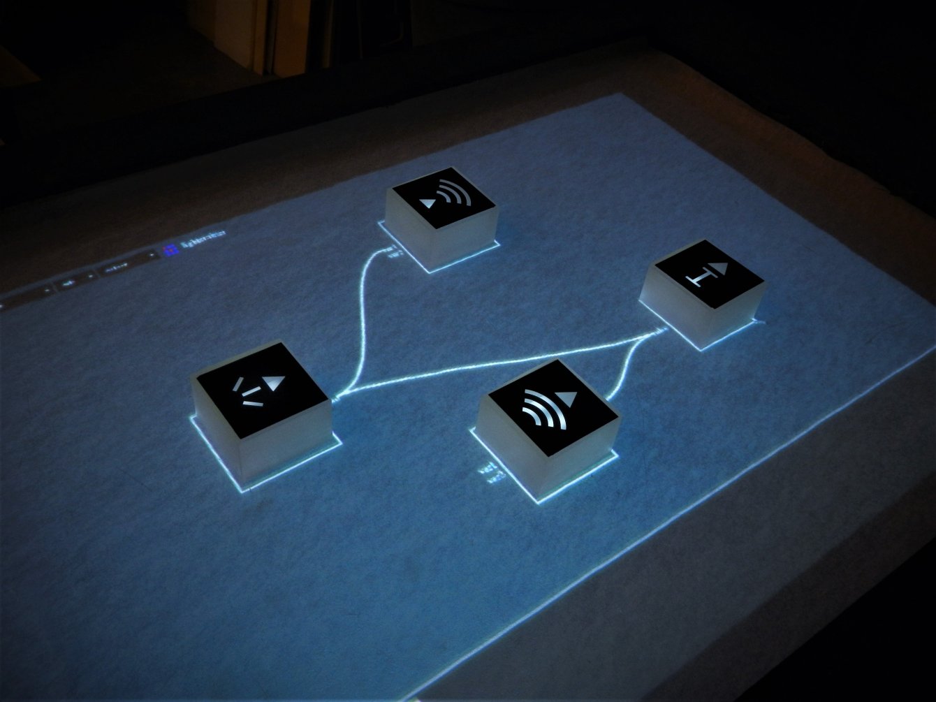
Now with all components, this is me moving modules around the table:
And actually linking two digital modules:
That in turn link our physical modules (I've moved them to other surface for illumination purposes):