This week's HTMaA assignment was to use input device to measure something. I was excited by the idea of using step response to measure changes in voltage over time. I started to think about how this could apply to my final project which will be an arcade game cabinet with a customizable control panel. After exploring step response a bit, I am still not convinced that it will be the best type of sensor for my final project, but it was fun to explore this week.
I started by looking at Matt Blackshaw's touchpad project and the loading example. Exploring these two projects was very helpful for deciphering the datasheet and comparing the differences between the ATTiny44 and ATTiny45 microcontrollers.
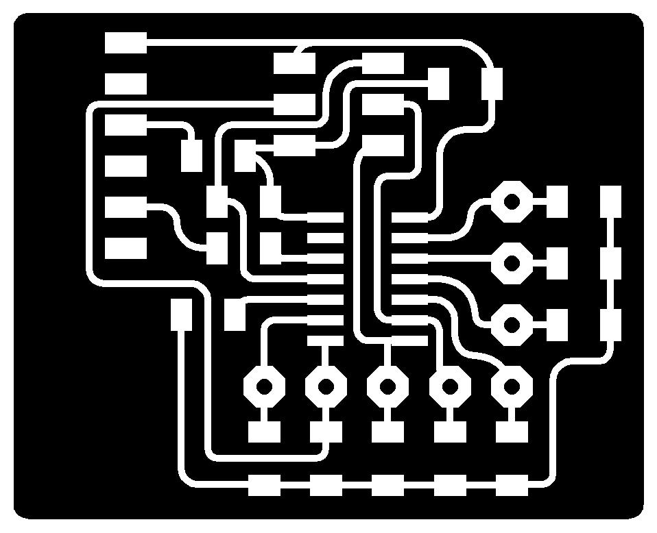
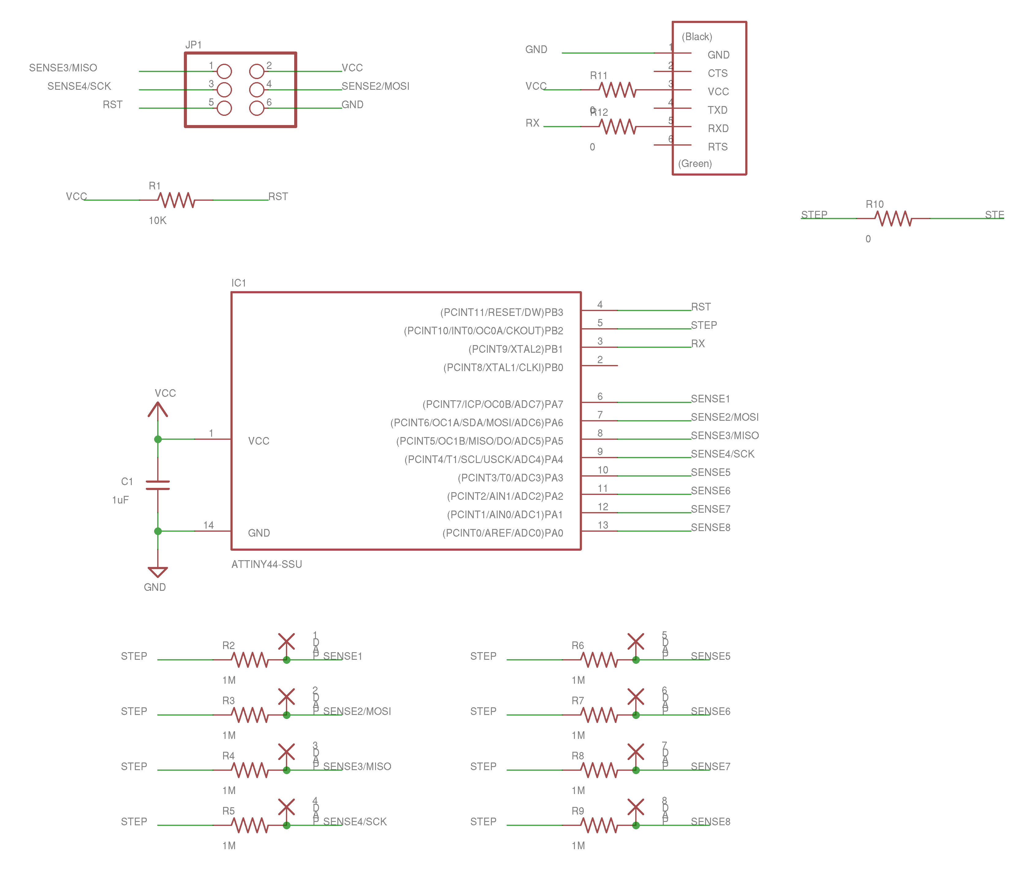
After I felt that I had a good understanding of the datasheet and how the two example projects worked, I set out to create my own design in Eagle. I think I was able to improve upon Matt's design by shrinking the overall footprint and eliminating the need for jumper wires (However, I did have to add two additional 0 ohm resistors).
Once I had my completed design, I milled and stuffed the board. While I was waiting for my board to mill, I started to create the program for my board. C files stuffed with all of the code quickly becomes overwhelming for me so I decided to separate out some of the code into a header file.
After programming the board, I tried to receive serial data via GNU screen, but all I received was gibberish. I remembered that Neil mentioned that when using the internal clock the timing sometimes has to be calibrated. After unsuccesfully trying to hook up my board to the oscilliscope, I met up with Brian Mayton in the CBA shop to ask for help. Brian showed me how to get the triggers and scaling write so that I could measure the serial communication on the screen. Brian also gave me a helpful tip that the 'U' character sends a nice pattern of 1010101. Once we had the scope hooked up we could see that the timing was way off! This indicates a larger issue than just calibrating the timing. After diving into my code we realized that I had specified the clock speed in my Makefile as 20Mhz instead of the internal 8Mhz. After a quick adjustment the data started flowing correctly!
Now that I had my board working as expected, I wanted to design the board on a two sided PCB where one side would be the copper input pads and the other side would contain all of the electronics. To do this, I decided to use the copper rivet via technique that Neil mentioned in class.
I created an eagle part for the .6mm copper rivets so they could be included in my board design and not drawn in later.
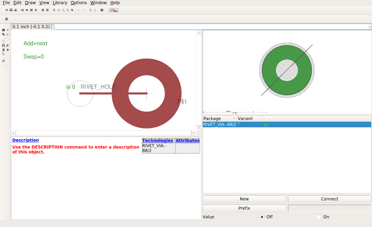
After a simple test I landed on a .88mm hole with a 2mm pad around it.
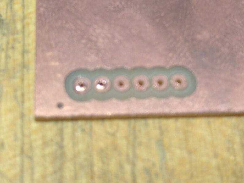
Now I started milling out my controller design on a larger two sided copper PCB. Once challenge with the larger board was making sure everything was level so that the traces would be properly cut out. After a adjusting the cut depth to .006" and making sure the board was pressed down flat I was able to achieve a nice mill.
It was a little bit of a challenge lining everything up properly since I was trying to mill two sides of the same board. I decide to cutout the board and the rivet holes before flipping over to the input side. It was less important that the rivet holes landed in the middle of the input pad compared with lining up with the traces. The cutout shape also helped me line up the board after flipping it.
Next steps:
If I were to take this project further, I would want to explore using V-USB to enable serial communication without the need for an FTDI cable.