The main goal for this session of the course is to learn different types of output devices and how to use them on our boards. We are asked to add an output device to a microcontroller board we've designed and program it to do something.
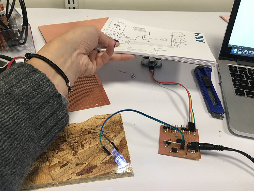
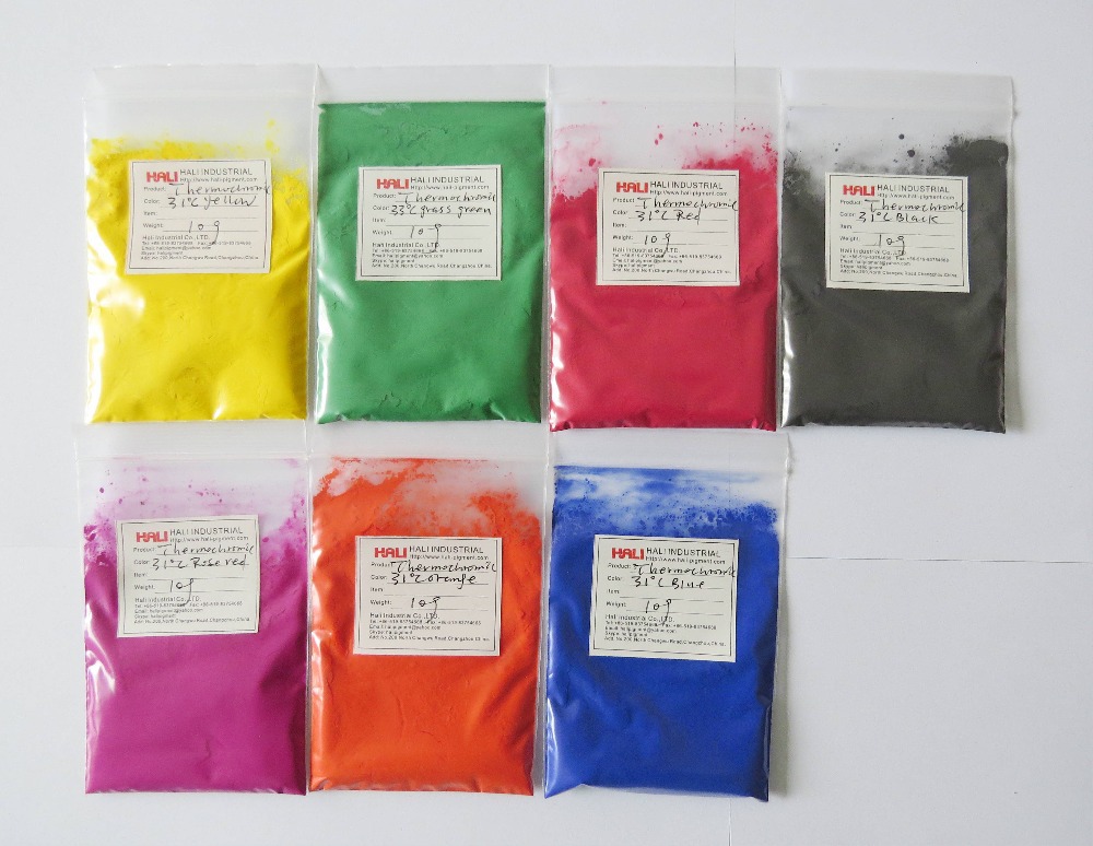
For this session I decided to design a board with a distance sensor and a variable temperature output. This will help me for my final project in order to change the thermochromic paint in my drawers.
It took me a while to fully understand all the options I had and take the design choice that I thougth would be the best. Ali helped me a lot with some basic electronics concepts.
Working with temperature is not easy as you need to make sure that you don't burn the materials. I looked at different options and these are the ones I found:
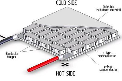
The Peltier modules are very small so I would need loads of them in order to cover the surface of my drawers. Although I found interesting looking at their design:
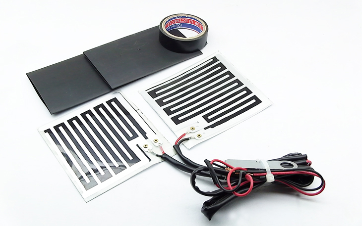
The hand grip warmers are a good option as they have a large surface. I ordered a couple but I am still waiting... I decided I would try with my own copper circuit for this weeks assignment as I had to do it myself and I would probably learn more from it.
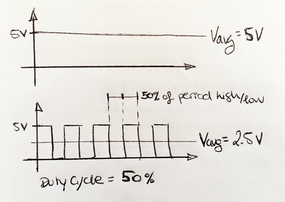
Working with temperature outputs need some kind of control over the power signal to make sure we don't burn our circuits or materials. For that end, we can use PMW (Pulse with modulation). PWM allows the control of the power supplied by using duty cycles. A low duty cycle corresponds to low power, because the power is off for most of the time.
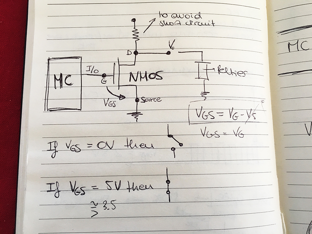
I need a transistor to control my circuit in order to heat up and cool down the surface.
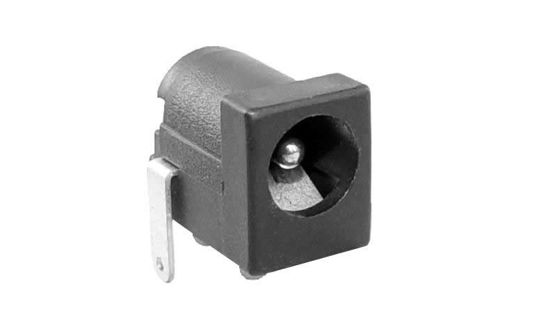
Ali also explained me how the power suply jack works and I found it quite interesting.
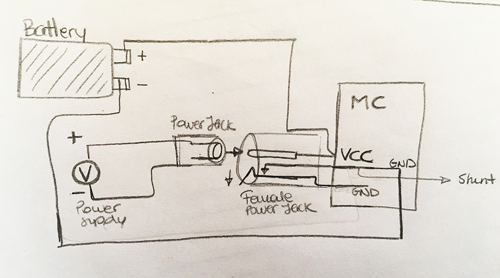
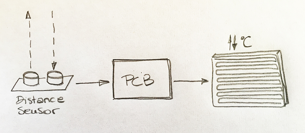
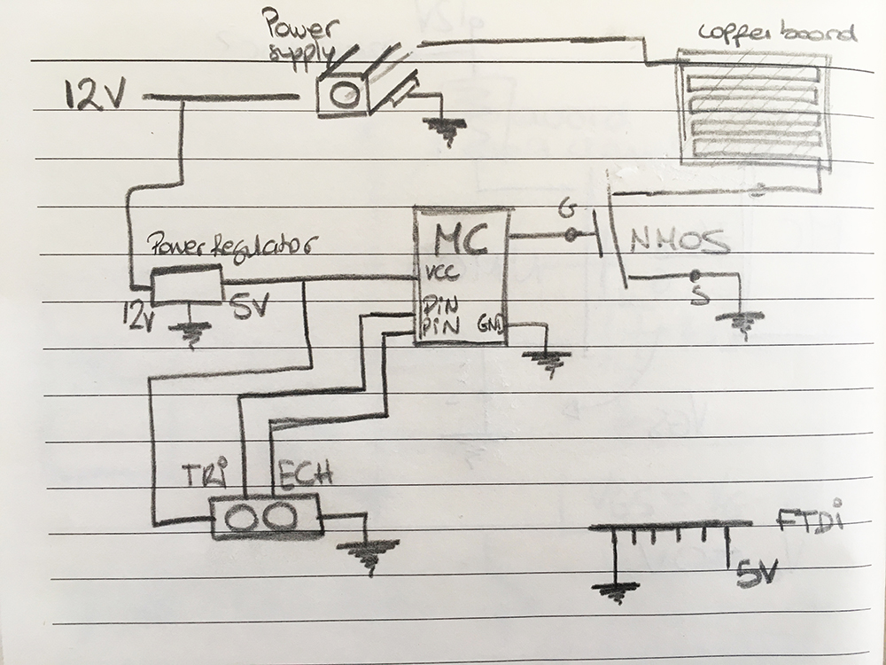
This is the initial design of my board:
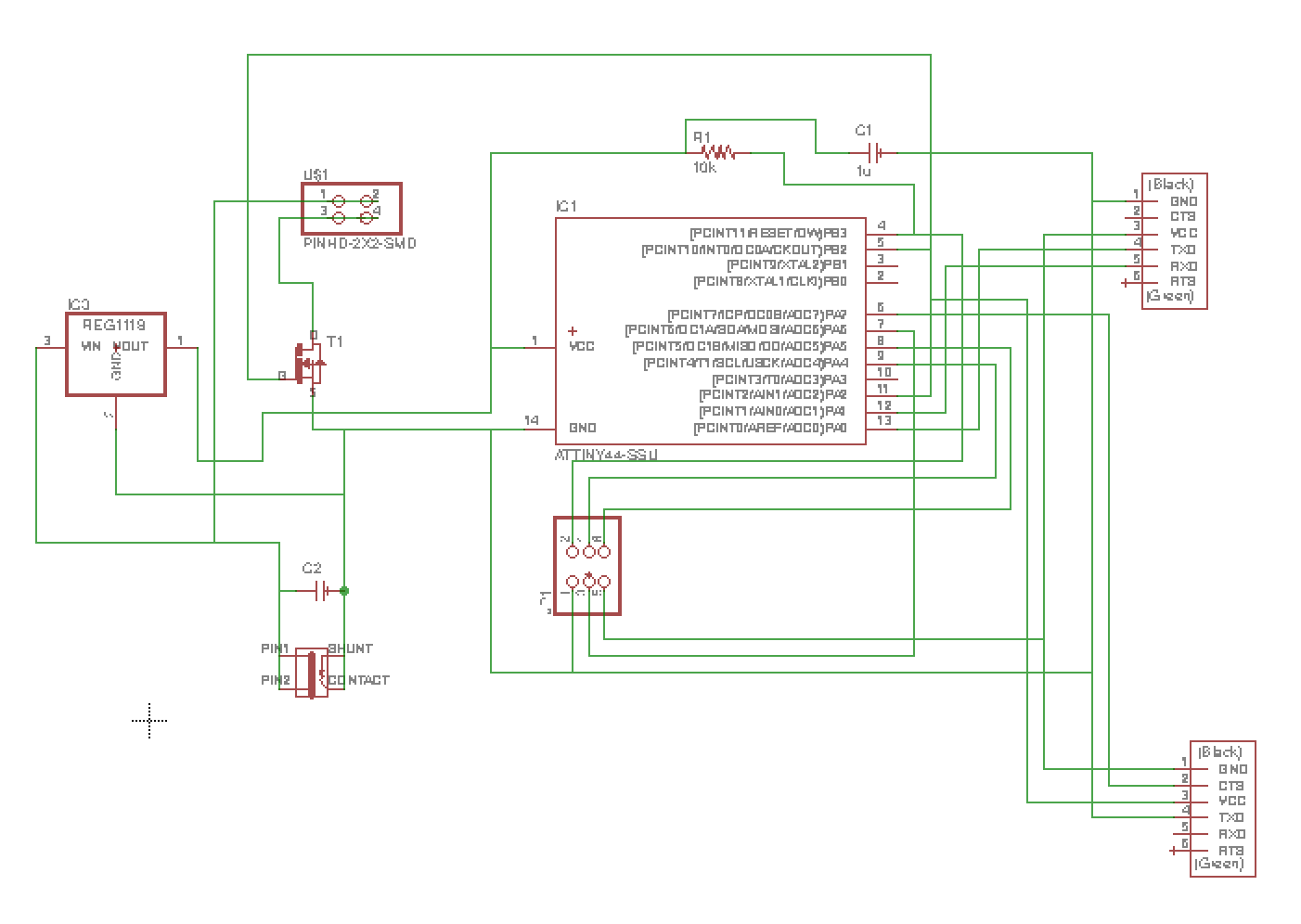
Once I figured out how everything worked, I designed my board in Eagle.
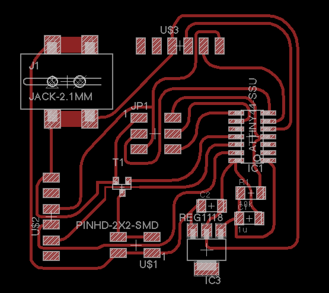
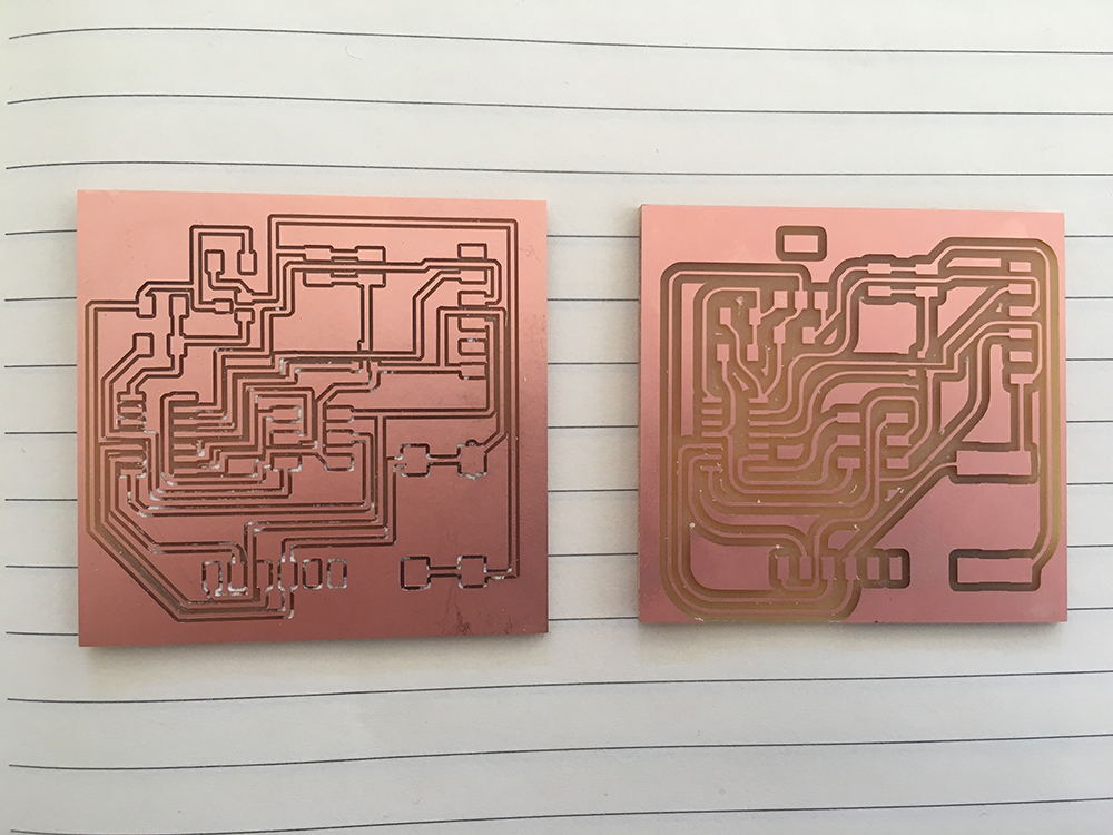
I did the routing and milled. But I reviewed it after milling and I found errors so I had to mill again.
Here's the two milled boards.
And here's the components I have to solder:
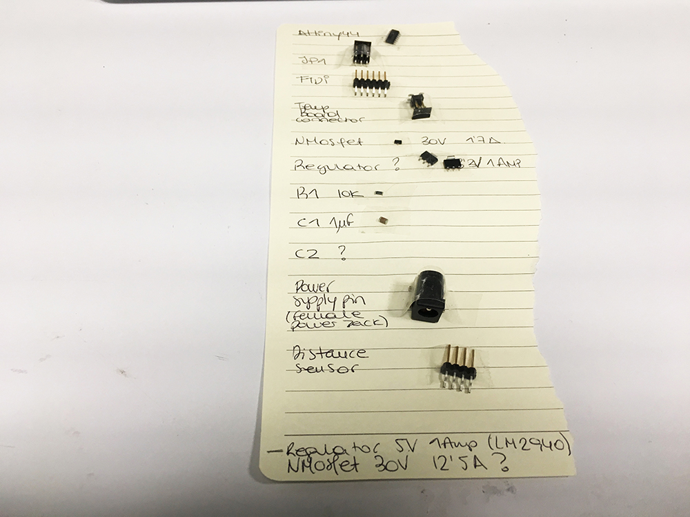
List of components:
After soldering and programming the board I finally managed to get a board running as expected.