The main goal for this session of the course is to learn about networks and communications. We are asked to design and build a wired &/or wireless network connecting at least two processors.
I wanted to try with a wireless module in order to be able to develop a phone app for my final project so I decided to use an ESP8266 from Adafruit.
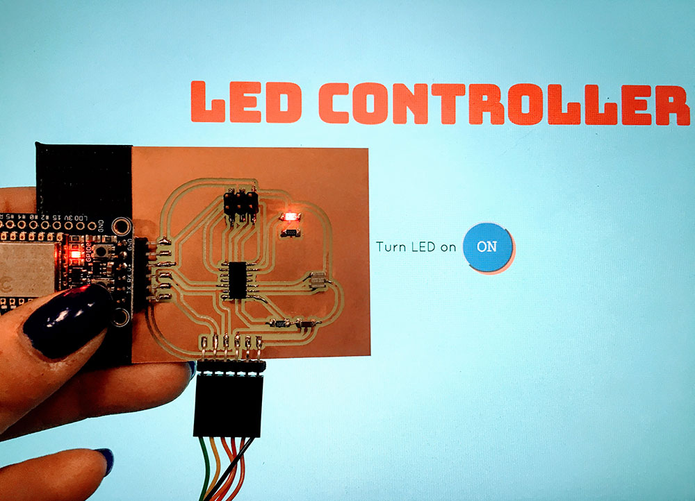
I don't have a lot of experience in electronics so I decided to make a simple board with an LED that would turn on when sending a value from the phone. I think it is a good starting point if you don't have extended knowledge in electronics or microcontrollers. So I'll try to document it as good as possible:
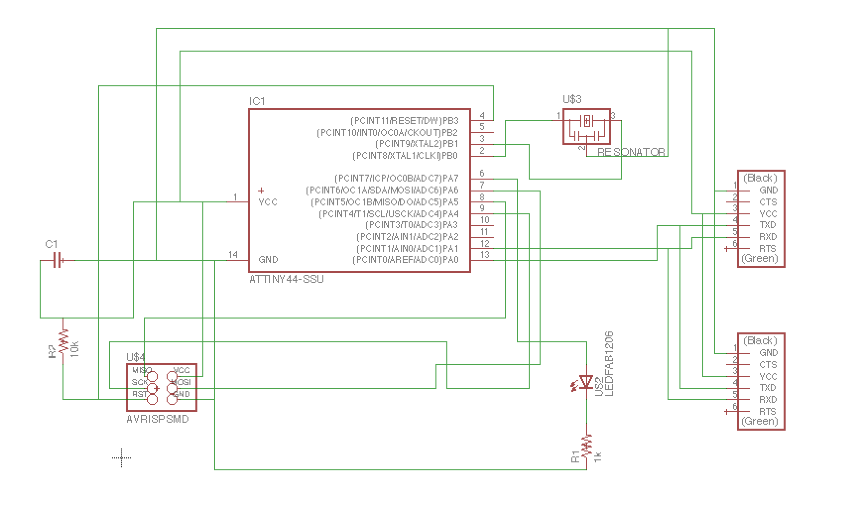
I first designed the board in Eagle. The main idea is to connect the ESP8266 to the Attiny44 in order to send the information received via wifi to the microcontroller. Here's a couple of considerations for the design:
The main problem of this design is that the TX and RX connections of the different modules can cause issues when trying to send data if the controllers are sending data at the same time. We will have to take this in account when programming.
Here's the list of the components needed:
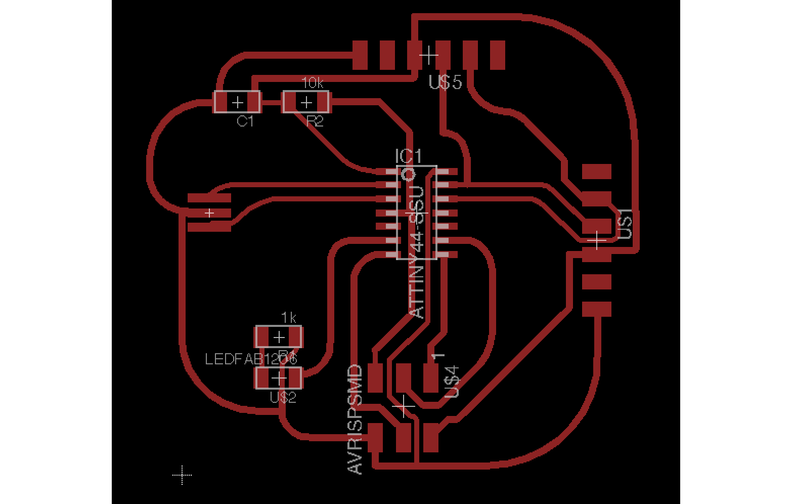
This is the final design:
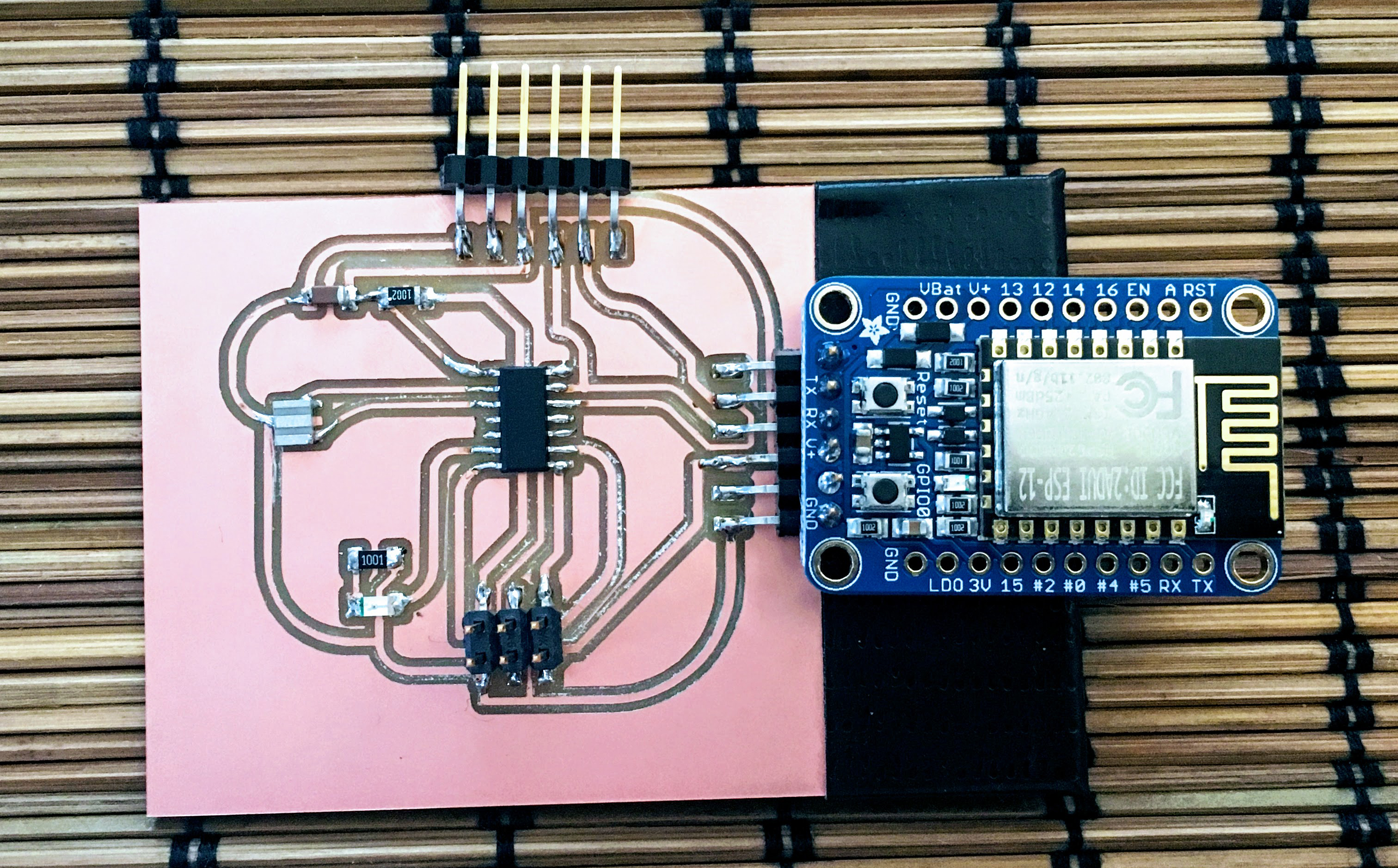
With the design ready, I milled the board. I had an issue when milling where one of the machines was milling too deep and I didn't manage to adjust the values so I had to change to the other Modela.
Once the board was ready I stuffed the board with all the components. I then added the ESP8266 and soldered it to the corresponding FTDI header. I also added a layer of black non-conductive tape to avoid having shorts on the bottom of the EPS8266.
First thing to do when the board is ready is try to check the proper operation of the different parts separately.
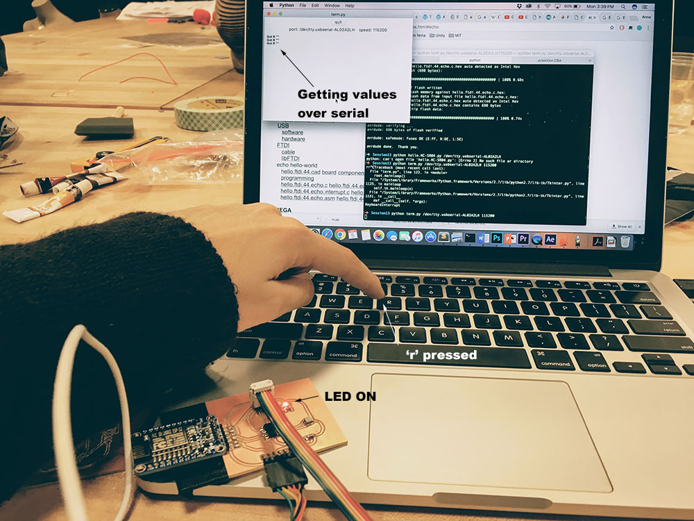
I used the basic script for programming the Attiny44 that turned the LED on when sending a value over serial.
Here's the script on GITHUB: BLINK LED ATTINY44
Steps to program the Attiny44: [Just a little review]
Once this is working, we will have to reprogram the Attiny44 in order to be able to program the ESP8266. We have to ensure that the Attiny is not sending any value over the TX pin. If the Attiny TX pin is set to output, the communication through that connection to the ESP8266 won't work. So now that you have ensured that the Attiny44 is working properly, follow next steps:
Now we are ready to test the ESP8266. We will use the Arduino IDE to program the wifi board so we need to import the corresponding libraries in our Arduino IDE. Follow this instructions to install the ESP8266 board Package.
Here you can find a nice explanation on how to program your ESP8266 board to act as a web server:
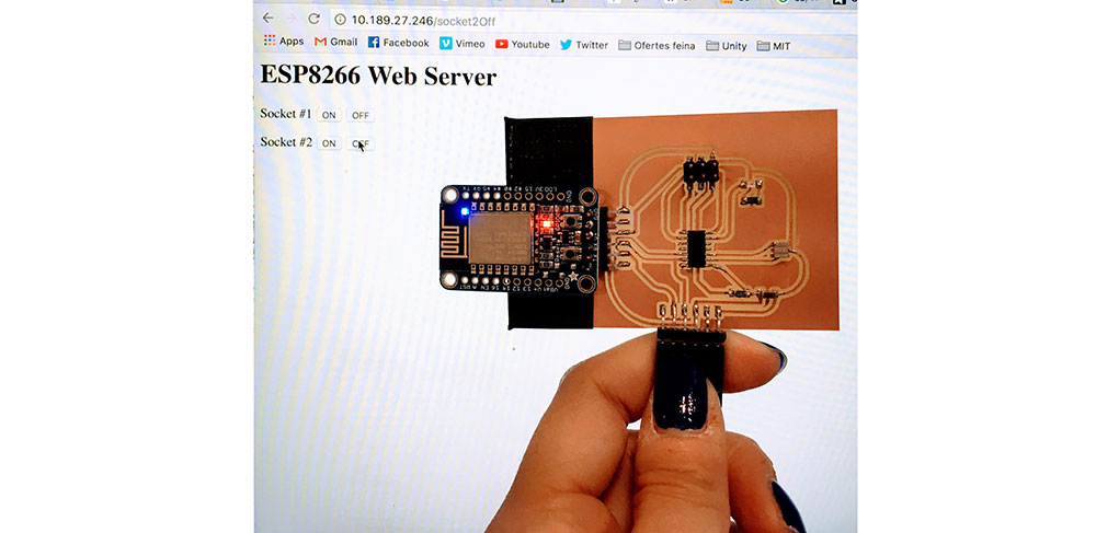
ESP8266 Web Server with Arduino IDE
In this tutorial, there's an explanation on how to set your ESP8226 board to act as a webserver and turn on and off the two LED's on the board from a remote client. Main steps to follow are:
Once the board is programmed, open the serial terminal in the Arduino IDE. The board should be trying to connect to the wifi network you especified and you should see the IP address that has been assigned to it.
If you open the browser from another device (laptop, phone, etc) and type the IP address followed by the arguments of the script (for example: http://10.189.52.226/socket1On), you should be able to see a webpage with 4 buttons that let you turn on and off the LED from the ESP8266 board.
Once the wifi board is working, adjust the code in the Arduino IDE to send values to the Attiny44. In our case, we want the wifi module to send an 'r' everytime we press the button. so we will use:
Serial.print('r');
This will send an 'r' character to the Attiny44 everytime we press the button on the website.
Update the code on the ESP8266 by putting it into boadload mode and comp&load from Arduino IDE.
Now you just need to upload the initial code for the Attiny44 [remember we commented first to avoid having issues with the communications?]. So basically:
And that's it!!! If you open a browser and go to the EPS8266 web server address you should see the button and when you press it, the LED on the Attiny44 should turn on.