The main goal for this session of the course is to have an overview of different input sensors and how to add them to our boards. We are asked to measure something: add a sensor to a microcontroller board and read it
I finally have decided what my final project is gonna be. I am gonna make a chest of drawers that can change its design depending on the content of each drawer. The drawers will have sensors inside that will measure how empty they are. Outside, they will have peltier modules and will be painted in thermocromic paint. Depending on the content of the drawers, their colour will change.
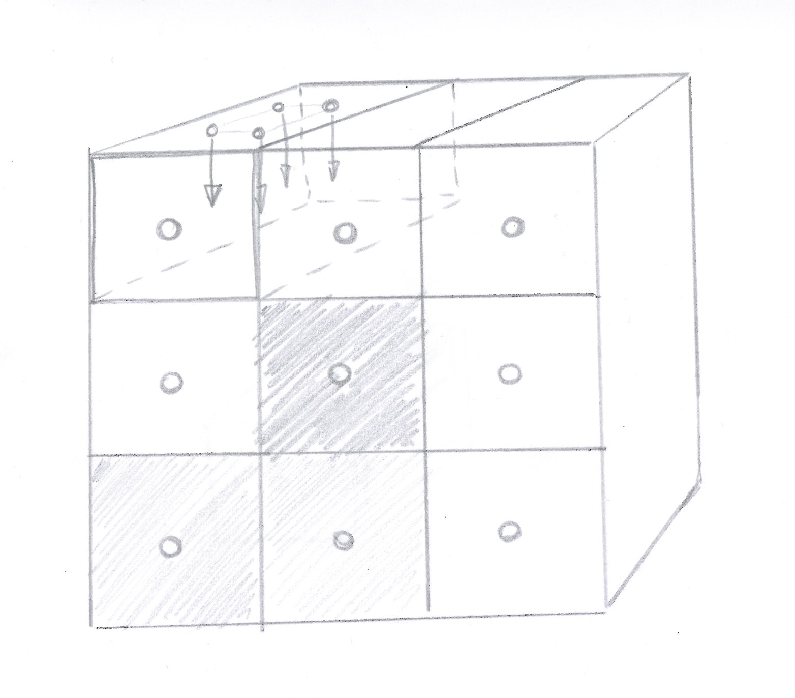
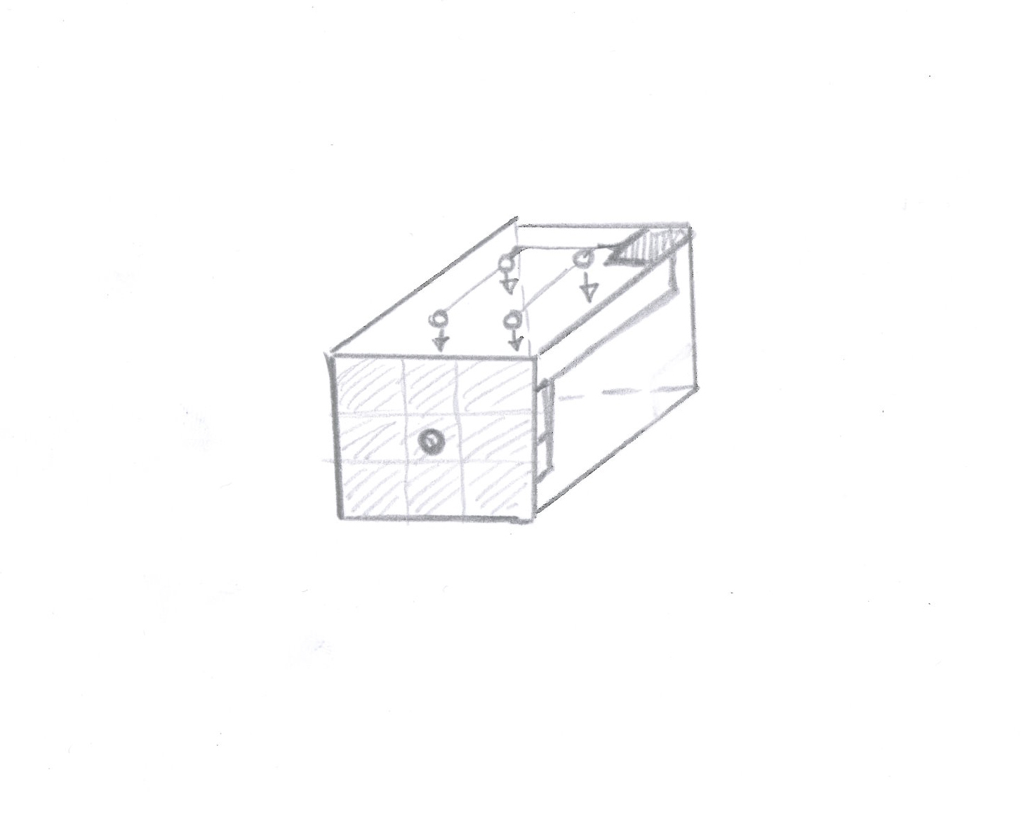
To do that, I am gonna use an array of distance sensors on top of each drawer, pointing downwards. This week is based on measurements so it is a good week to make some advances for the final project.
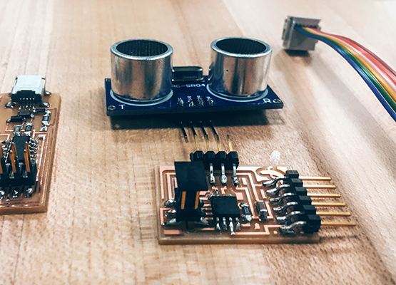
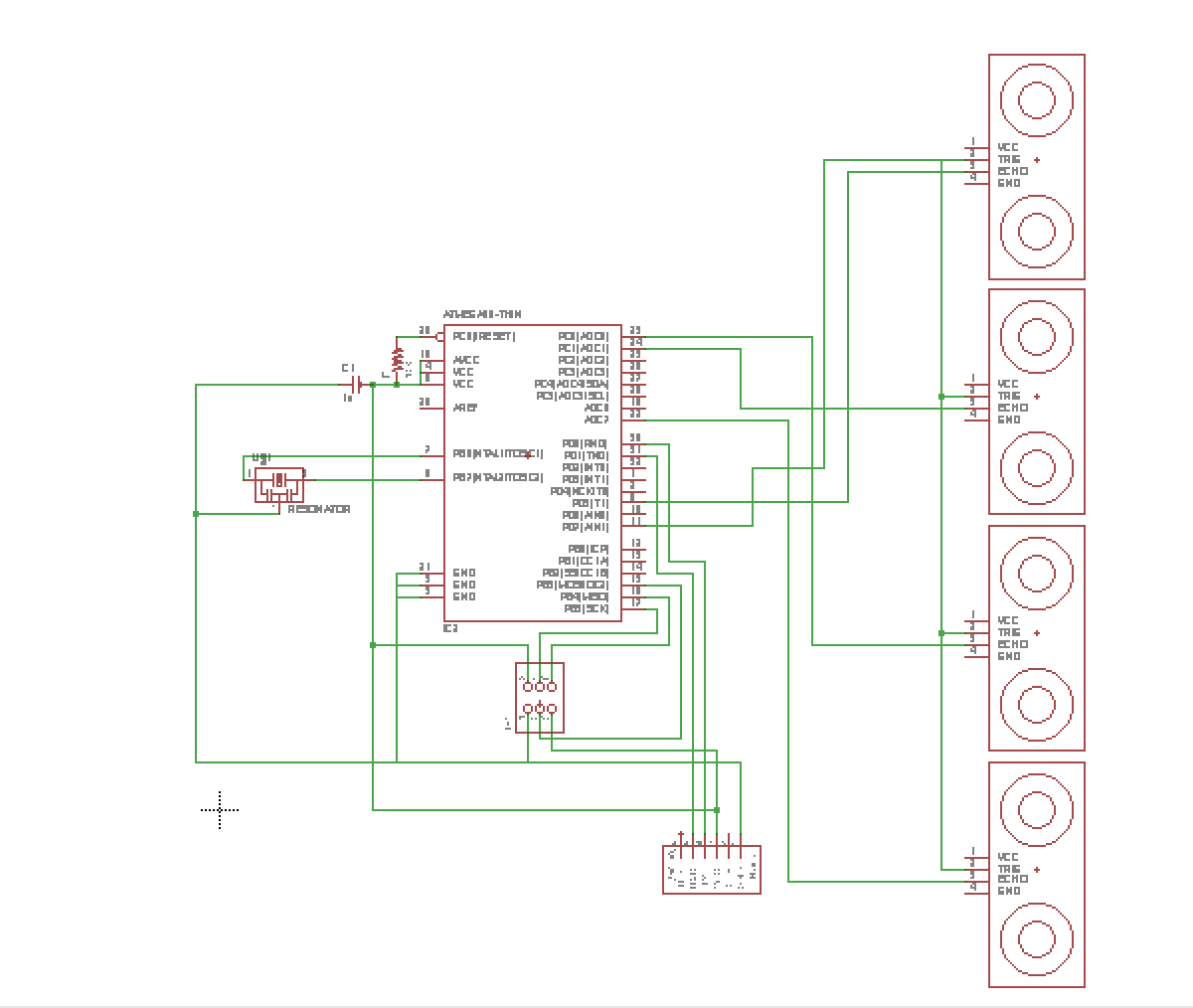
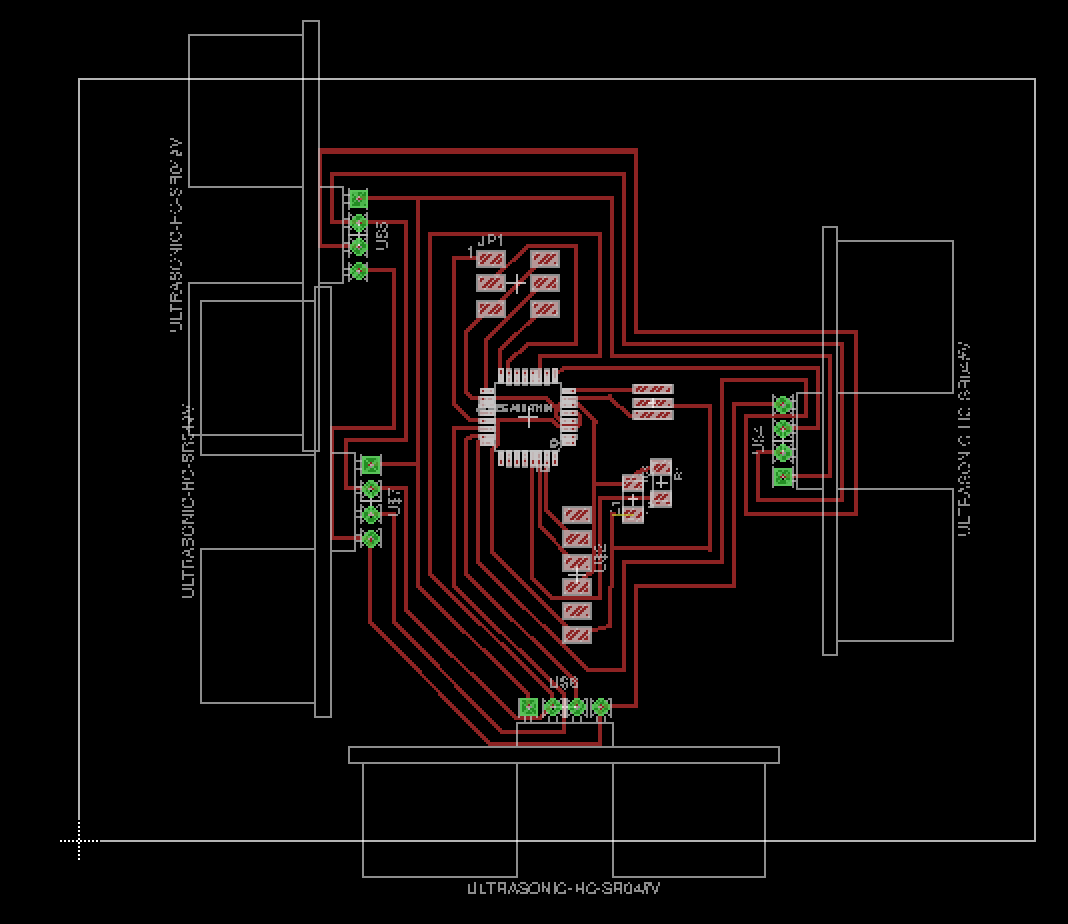
Using Eagle, I designed a board with four sonar sensors. I decided to use the Atmega88 as it has more pins and the communications between the modules will be simpler. I will have to deal with communication in the future for the peltier modules.
Eric explained my how I could use one microcontroller and connect all the sensors to it. I chose the distance sensors from the class website (HC-SR04). He told me I could make the timer myself with the loop of the code by counting the times it looped before getting the signal back on the echo pin. With this information I could do the maths for the different times of travel of the signal.
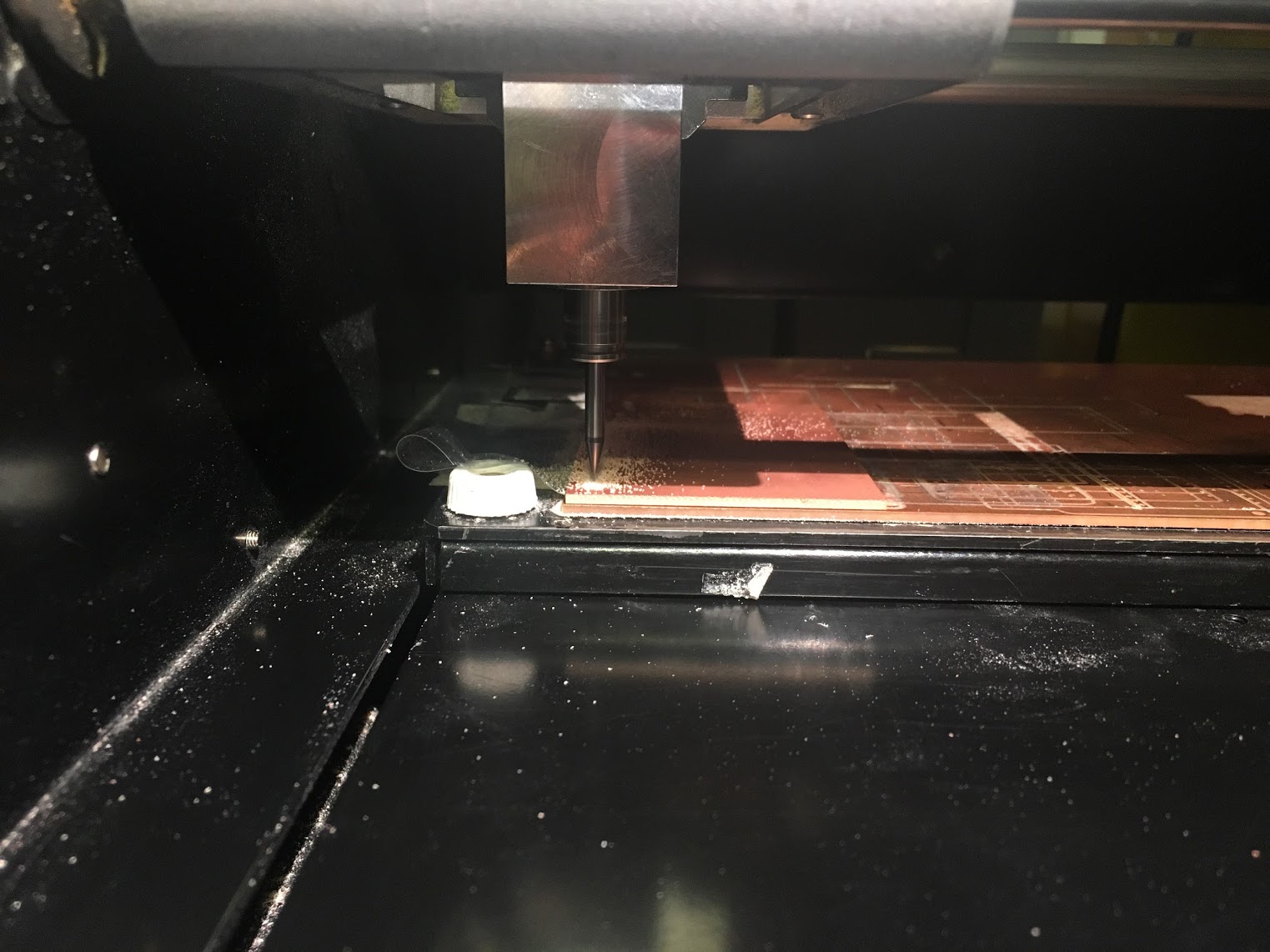
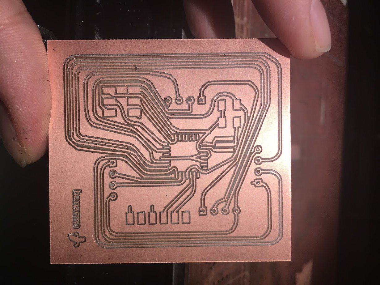
I am still not very familiar with Eagle and I had a hard time with the design. I tried designing the board by myself but I couldn't find a way to route it. So I ended up milling a first board with lost connections that I though I would fix adding bits of cable here and there. I know, pretty bad. I discarded the idea quickly and threw away the milled board.
Fortunately, after all my failures, Ali had a moment to explain me some concepts in electronics that I didn't understand. He explained me some basic concepts about pull-up resistors and about the different uses for capacitors.
He helped me with some tecniques to make the design simpler. For example, I was first trying to connect all the trigger pins from the sensor to different pins of the board and he showed me how I could only connect to one pin of the board and send the message simulateously to all the sensors.
As all this design process took me really long, so I didn't have time to mill and solder my board for the final project.
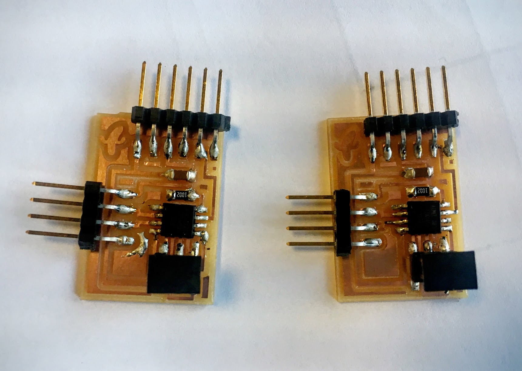
However, I had time to mill, solder and program the example board with one sensor.
I soldered a couple of boards for one sensor. I am getting better at soldering :) and I am kind of enjoying it.
I finally programmed the board with the example code from class:
TEST