This week, my goal is to apply synchronous detection to a laser diode and phototransistor, for the detector of the confocal 3D scanner.
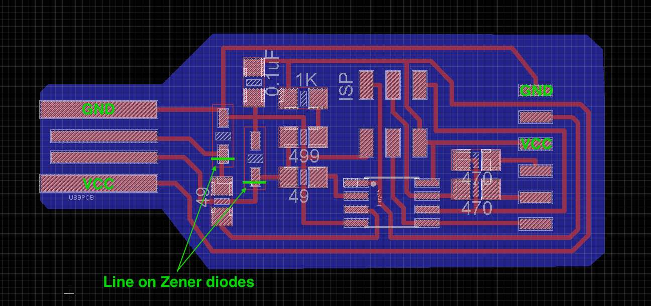
I followed the tutorial by Prashant to make my own FTDI cable! I used the same process as in the electronics production week. Here is an image of the board with GND, VCC, and polarity of Zener diodes indicated. It took me some time to correlate the schematic and the traces.
I programmed the board with the
As recommended by Prashant, I next tested the board on Neil's hello FTDI echo board from embedded programming week. In
I modified Neil's synchronous detection board to drive an external laser diode rather than a surface mount LED. In particular, I replaced the copper pads for the LED package with pads for a pair of header pins, and I increased the current for more power from the laser diode.
Neil's page links to the phototransistor OP580DA. So DA stands for Darlington. The datasheet is here: http://optekinc.com/datasheets/OP580DA.pdf Photo darlington devices are normally used in applications where light signals are low and more current gain is needed than is possible with phototransistors. At 1 mW/cm2, OP520 gives 0.2 mA, whereas OP580A gives about 22 mA. So OP580A gives about 100x more current than OP520. Note that OP580DA is matched to the LED OP280. The datasheet for OP520 is here: http://optekinc.com/datasheets/OP520-521.PDF The OP520 and OP521 are mechanically and spectrally matched to the OP250 series infrared LEDs. Go for OP520 which has optical filter to block visible light, and OP250 as LED. Went for OP522 which is clear, and a red LED. Checked the LED orientation with a multimeter. the green line adjacent to the cathode, same as with the Zener diode Darker green mark is the collector.
I modified Neil's synchronous detection board to drive an external laser diode rather than a surface mount LED. In particular, I replaced the copper pads for the LED package with pads for a pair of IDC header pins. I used GIMP to modify the design. I learned a few GIMP hotkeys
| Select rectangle | R |
| Select → Float | Control + Shift + L |
| Fill with foreground (black) | Control + , |
| Fill with background (white) | Control + . |
and to increase the size of the image used Image → Canvas size.
In order to increase the power from the laser diode, I decreased the resistance of the current limiting resistor. An illegible sticker on the laser diode indicates
| Voltage | 3V DC |
| Current | 19 mA (?) |
| Power | 3.64 mW (?) |
| Wavelength | 660 nm |
Using this calculator, I calculated the resistance of the current limiting resistor. Since the supply voltage is 5 V (Sam noted that FTDI cables do 5 V power and 3.3 V logic), the voltage drop across the LED is 3 V, and the desired current is 3.6 mA, the resistance should be 555 Ohm (instead of the original 1 kOhm) and the resistor dissipates 7.2 mW. I used a 560 Ohm SMD resistor. Note the upper bound on a USB port is 100 mA, so we should be far from that upper bound. Also here is some background on laser diodes.